Hydraulic ram
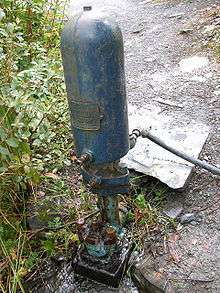
A hydraulic ram, or hydram, is a cyclic water pump powered by hydropower. It takes in water at one "hydraulic head" (pressure) and flow rate, and outputs water at a higher hydraulic head and lower flow rate. The device uses the water hammer effect to develop pressure that allows a portion of the input water that powers the pump to be lifted to a point higher than where the water originally started. The hydraulic ram is sometimes used in remote areas, where there is both a source of low-head hydropower and a need for pumping water to a destination higher in elevation than the source. In this situation, the ram is often useful, since it requires no outside source of power other than the kinetic energy of flowing water.
History
_ubt.ogv.jpg)
In 1772, John Whitehurst of Cheshire, United Kingdom, invented a manually controlled precursor of the hydraulic ram called the "pulsation engine" and installed the first one at Oulton, Cheshire to raise water to a height of 4.9 metres (16 ft).[1][2] In 1783, he installed another in Ireland. He did not patent it, and details are obscure, but it is known to have had an air vessel.
The first self-acting ram pump was invented by the Frenchman Joseph Michel Montgolfier (best known as a co-inventor of the hot air balloon) in 1796 for raising water in his paper mill at Voiron.[3] His friend Matthew Boulton took out a British patent on his behalf in 1797. The sons of Montgolfier obtained a British patent for an improved version in 1816,[4] and this was acquired, together with Whitehurst's design, in 1820 by Josiah Easton, a Somerset-born engineer who had just moved to London.
Easton's firm, inherited by his son James (1796–1871), grew during the nineteenth century to become one of the more important engineering manufacturers in the United Kingdom, with a large works at Erith, Kent. They specialised in water supply and sewerage systems worldwide, as well as land drainage projects. Eastons had a good business supplying rams for water supply purposes to large country houses, farms, and village communities. Some of their installations still survived as of 2004, one such example being at the hamlet of Toller Whelme, in Dorset.
The firm closed in 1909, but the ram business was continued by James R Easton. In 1929, it was acquired by Green & Carter [5] of Winchester, Hampshire, who were engaged in the manufacturing and installation of Vulcan and Vacher Rams.
The first US patent was issued to Joseph Cerneau (or Curneau) and Stephen (Étienne) S. Hallet (1755-1825) in 1809.[6][7] US interest in hydraulic rams picked up around 1840, as further patents were issued and domestic companies started offering rams for sale. Toward the end of the 19th century, interest waned as electricity and electric pumps became widely available.
By the end of the twentieth century interest in hydraulic rams has revived, due to the needs of sustainable technology in developing countries, and energy conservation in developed ones. A good example is AID Foundation International in the Philippines, who won an Ashden Award for their work developing ram pumps that could be easily maintained for use in remote villages.[8] The hydraulic ram principle has been used in some proposals for exploiting wave power, one of which was discussed as long ago as 1931 by Hanns Günther in his book In hundert Jahren.[9]
Some later ram designs in the UK called compound rams were designed to pump treated water using an untreated drive water source, which overcomes some of the problems of having drinking water sourced from an open stream.[10]
In 1996 an English engineer, Frederick Philip Selwyn, patented a ‘fluid pressure amplifier’ which differed in many ways to the contemporary ram technology by the development of a venturi effect waste valve.[11]
Known as the Papa pump, this utilises the low pressure generated by high velocity water flow around a curve-shaped elastomeric valve (with low pressure loss) to allow a valve design that enables rapid closure and with a relatively small cross sectional area and low weight. The venturi valve is configured as a ring section positioned around the supply inlet of the pump with the delivery outlet of the pump being directly in line. The design allowed the pump structure to be concentric and therefore inherently strong and upon closure of the valve, permits efficient water delivery by acting in line with the supply via a second smaller venturi effect delivery non return valve. The elastomeric material and operation of these valves also allows them to self-return without weight or spring assistance. A pressure vessel installed on a tee connected to the delivery port of the pump provides the pulsed flow accumulation means. This unique technology and design dramatically reduced the weight, manufacturing cost and number of components required - as well as provided an overall improvement in efficiency.
Additional patents granted to Selwyn have since been developed by UK companies Papa Ltd and Water Powered Technologies Ltd[12] of Bude, Cornwall, further enhancing the technology to include a composite material injection-moulded pump allowing for relatively low cost mass production whilst maintaining high strength, low weight and high performance previously only attainable with metal units.
Other novel developments include an automatic regulator valve which can be simply installed to the pumps to allow the maximum utilisation of water supply from low or seasonally variable water sources without the need to manually adjust the pumps - as well as much larger pump versions with 1 metre diameter inlets for large river, marine tidal and flood applications. Systems have also been developed and utilised for rainwater harvesting, water treatment and other water utility applications.
The new scalable technology, manufacturing processes and materials and the ability to integrate with other systems should allow the 21st century ram pump to regain its recognition as a world leader in energy efficient water supply as well as new roles in energy generation, irrigation and flood support networks.
Construction and principle of operation
A traditional hydraulic ram has only two moving parts, a spring or weight loaded "waste" valve sometimes known as the "clack" valve and a "delivery" check valve, making it cheap to build, easy to maintain, and very reliable. The Papa hydraulic ram pump also has only two moving parts. However, these are not mechanical but instead rely on the elastomeric properties of the main valve and non-return valve which are low-cost, reliable and easy to replace. In addition, there is a drive pipe supplying water from an elevated source and a delivery pipe, taking a portion of the water that comes through the drive pipe to an elevation higher than the source.
Sequence of operation
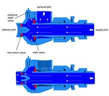
1. Inlet – drive pipe
2. Free flow at waste valve
3. Outlet – delivery pipe
4. Waste valve
5. Delivery check valve
6. Pressure vessel
A simplified hydraulic ram is shown in Figure 2. Initially, the waste valve [4] is open, and the delivery valve [5] is closed. The water in the inlet pipe [1] starts to flow under the force of gravity and picks up speed and kinetic energy until the increasing drag force closes the waste valve. The momentum of the water flow in the inlet pipe against the now closed waste valve causes a water hammer that raises the pressure in the pump, opens the delivery valve [5], and forces some water to flow into the delivery pipe [3]. Because this water is being forced uphill through the delivery pipe farther than it is falling downhill from the source, the flow slows; when the flow reverses, the delivery check valve closes. Meanwhile, the water hammer from the closing of the waste valve also produces a pressure pulse which propagates back up the inlet pipe to the source where it converts to a suction pulse that propagates back down the inlet pipe. This suction pulse, with the weight or spring on the valve, pulls the waste valve back open and allows the process to begin again.
A pressure vessel [6] containing air cushions the hydraulic pressure shock when the waste valve closes, and it also improves the pumping efficiency by allowing a more constant flow through the delivery pipe. Although the pump could in theory work without it, the efficiency would drop drastically and the pump would be subject to extraordinary stresses that could shorten its life considerably. One problem is that the pressurized air will gradually dissolve into the water until none remains. One solution to this problem is to have the air separated from the water by an elastic diaphragm (similar to an expansion tank); however, this solution can be problematic in developing countries where replacements are difficult to procure. Another solution is to have a mechanism such as a snifting valve that automatically inserts a small bubble of air when the suction pulse mentioned above reaches the pump.[13] Another solution is to insert an inner tube of a car or bicycle tire into the pressure vessel with some air in it and the valve closed. This tube is in effect the same as the diaphragm, but it is implemented with more widely available materials. The air in the tube cushions the shock of the water the same as the air in other configurations does.
Efficiency
A typical energy efficiency is 60%, but up to 80% is possible. This should not be confused with the volumetric efficiency, which relates the volume of water delivered to total water taken from the source. The portion of water available at the delivery pipe will be reduced by the ratio of the delivery head to the supply head. Thus if the source is 2 meters above the ram and the water is lifted to 10 meters above the ram, only 20% of the supplied water can be available, the other 80% being spilled via the waste valve. These ratios assume 100% energy efficiency. Actual water delivered will be further reduced by the energy efficiency factor. In the above example, if the energy efficiency is 70%, the water delivered will be 70% of 20%, i.e. 14%. Assuming a 2-to-1 supply head to delivery head ratio and 70% efficiency, the delivered water would be 70% of 50%, i.e. 35%. Very high ratios of delivery to supply head usually result in lowered energy efficiency. Suppliers of rams often provide tables giving expected volume ratios based on actual tests.
Drive and delivery pipe design
Since both efficiency and reliable cycling depend on water hammer effects, the drive pipe design is important. It should be between 3 and 7 times longer than the vertical distance between the source and the ram. Commercial rams may have an input fitting designed to accommodate this optimum slope.[14] The diameter of the supply pipe would normally match the diameter of the input fitting on the ram, which in turn is based on its pumping capacity. The drive pipe should be of constant diameter and material, and should be as straight as possible. Where bends are necessary, they should be smooth, large diameter curves. Even a large spiral is allowed, but elbows are to be avoided. PVC will work in some installations, but steel pipe is preferred, although much more expensive. If valves are used they should be a free flow type such as a ball valve or gate valve.
The delivery pipe is much less critical since the pressure vessel prevents water hammer effects from traveling up it. Its overall design would be determined by the allowable pressure drop based on the expected flow. Typically the pipe size will be about half that of the supply pipe, but for very long runs a larger size may be indicated. PVC pipe and any necessary valves are not a problem.
Starting operation
A ram newly placed into operation or which has stopped cycling must be started as follows. If the waste valve is in the raised (closed) position, which is most common, it must be pushed down manually into the open position and released. If the flow is sufficient, it will then cycle at least once. If it does not continue to cycle, it must be pushed down repeatedly until it cycles continuously on its own, usually after three or four manual cycles. If the ram stops with the waste valve in the down (open) position it must be lifted manually and kept up for as long as necessary for the supply pipe to fill with water and for any air bubbles to travel up the pipe to the source. This may take a minute or more. Then it can be started manually by pushing it down a few times as described above. Having a valve on the delivery pipe at the ram makes starting easier. Close the valve until the ram starts cycling, then gradually open it to fill the delivery pipe. If opened too quickly it will stop the cycling. Once the delivery pipe is full the valve can be left open.
Common operational problems
Failure to deliver sufficient water may be due to improper adjustment of the waste valve, having too little air in the pressure vessel, or simply attempting to raise the water higher than the level of which the ram is capable.
The ram may be damaged by freezing in winter, or loss of air in the pressure vessel leading to excess stress on the ram parts. These failures will require welding or other repair methods and perhaps parts replacement.
It is not uncommon for an operating ram to require occasional restarts. The cycling may stop due to poor adjustment of the waste valve, or insufficient water flow at the source. Air can enter if the supply water level is not at least a few inches above the input end of the supply pipe. Other problems are blockage of the valves with debris, or improper installation, such as using a supply pipe of non uniform diameter or material, having sharp bends or a rough interior, or one that is too long or short for the drop, or is made of an insufficiently rigid material. A PVC supply pipe will work in some installations but is not as optimal as steel.
Water-powered pump
An alternative to the hydraulic ram is the water-powered pump. It can be used if a high flow rate at high head ratio is required. A water-powered pump unit is a hydraulic turbine coupled to a water pump. The motive power needed by the pump is generated by the hydraulic turbine from the available low head water energy.[15]
See also
| Wikimedia Commons has media related to Hydraulic rams. |
References
- ↑ Whitehurst, John (1775). "Account of a Machine for Raising Water, executed at Oulton, in Cheshire, in 1772". Philosophical Transactions of the Royal Society. London: Royal Society. 65: 277–279. doi:10.1098/rstl.1775.0026.
- ↑ Descriptions of Whitehurst's and Montgolfier's pumps appear in: James Ferguson and David Brewster, Lectures on Select Subjects … , 3rd ed. (Edinburgh, Scotland: Stirling & Slade, etc., 1823), vol. 2, pages 287-292; plates, p. 421.
- ↑ de Montgolfier, J.M. (1803). "Note sur le bélier hydraulique, et sur la manière d'en calculer les effets" [Note on the hydraulic ram, and on the method of calculating its effects] (PDF). Journal des Mines, 13 (73) (in French). pp. 42–51.
- ↑ See, for example: "New Patents: Pierre François Montgolfier," The Annals of Philosophy, 7 (41) : 405 (May 1816).
- ↑ Green and Carter – Hydraulic Ram Pump inventors and patentees.
- ↑ See:
- Executive Documents of the House of Representatives at the Second Session of the Twenty-first Congress … , vol. 2 (Washington, D.C.: Duff Green, 1831), pages 328 and 332.
- Letter from Stephen S. Hallet to U.S. President James Madison, September 9, 1808. Available on-line at: U.S. National Archives.
- ↑ See also Robert Fulton's hydraulic ram pump: letter to Thomas Jefferson, March 28, 1810. Available on-line at: U.S. National Archives.
- ↑ "AID Foundation 2007 Ashden Award". Retrieved 2008-07-09.
- ↑ Hanns Günther (Walter de Haas) (1931). In hundert Jahren. Kosmos.
- ↑ Interpretation board at the Lost Gardens of Heligan, Cornwall
- ↑ Frederick Philip Selwyn, pdfpiw.uspto.gov, "Fluid pressure amplifier", U.S. Patent no. 6,206,041 (filed: 2 April 1997; issued: 27 March 2001).
- ↑ Water Powered Technologies – Composite Hydraulic Ram Pump inventors and patentees.
- ↑ Practical Answers: Hydraulic Ram Pumps
- ↑ Hydraulic Ram Pumps, John Perkin
- ↑ Nagarjuna Sagar Water Powered pump (WPP) Units
Further reading
- Crowley, C.A. (August 1937). "Hydraulic rams furnish water supply to country homes". Popular Mechanics: 306–311.
- Crowley, C.A. (September 1937). "Hydraulic rams furnish water supply to country homes". Popular Mechanics: 437–477.
- Toothe v. Bryce, 25 Atlantic Reporter, pp. 182–190.
- Iversen, H.W. (June 1975). "An analysis of the hydraulic ram". Journal of Fluids Engineering: 191–196.
- Hydraulic Ram: Fixing & Working. Spons' Workshop Receipts. vol II. London: Spon. 1921. pp. 457–465.
- Hydraulic rams - a comparative investigation (by J.H.P.M. Tacke). Communications on Hydraulic and Geotechnical Engineering, ISSN 0169-6548. Report 88-1. Delft University of Technology, Faculty of Civil Engineering. 1988.
External links
- Film: Hydraulic ram on summer children's camp of Pterodactylus - Restless Water i European project "EnergyBits" (English version)
- the same film in French / le même film français
- Web page: Hydraulic ram on summer children's camp of Pterodactylus (yet in the Czech language, we prepare English)
- Ram pump (hydraulic ram)
- Ram pump home made
- Ram pump
- How it works
- Build a hydraulic ram
- Hydraulic ram : the French reference site
- How the Papa ram pump works