Ohm
| Ohm | |
|---|---|
|
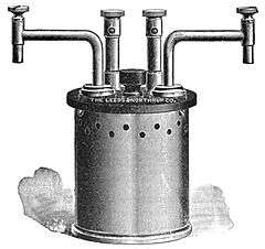
A laboratory one-Ohm standard resistor. | |
| Unit information | |
| Unit system | SI derived unit |
| Unit of | Electrical resistance |
| Symbol | Ω |
| Named after | Georg Ohm |
| In SI base units: | kg⋅m2⋅s−3⋅A−2 |
The ohm (symbol: Ω) is the SI derived unit of electrical resistance, named after German physicist Georg Simon Ohm. Although several empirically derived standard units for expressing electrical resistance were developed in connection with early telegraphy practice, the British Association for the Advancement of Science proposed a unit derived from existing units of mass, length and time and of a convenient size for practical work as early as 1861. The definition of the ohm was revised several times. Today the definition of the ohm is expressed from the quantum Hall effect.
Definition

The ohm is defined as an electrical resistance between two points of a conductor when a constant potential difference of 1 volt, applied to these points, produces in the conductor a current of 1 ampere, the conductor not being the seat of any electromotive force.[1]

in which the following units appear: volt (V), ampere (A), siemens (S), watt (W), second (s), farad (F), joule (J), kilogram (kg), metre (m), and coulomb (C).
In many cases the resistance of a conductor in ohms is approximately constant within a certain range of voltages, temperatures, and other parameters. These are called linear resistors. In other cases resistance varies (e.g., thermistors).
Commonly used multiples and submultiples in electrical and electronic usage are the microohm, milliohm, kilohm, megohm, and gigaohm;[2] the term "gigohm", though not official, is in common use for the latter.[3]
In alternating current circuits, electrical impedance is also measured in ohms (Ω).
Conversions
The siemens (symbol: S) is the SI derived unit of electric conductance and admittance, also known as the mho (ohm spelled backwards, symbol is ℧); it is the reciprocal of resistance in ohms (Ω).
Power as a function of resistance
The power dissipated by a resistor may be calculated from its resistance, and the voltage or current involved. The formula is a combination of Ohm's Law and Joule's law:

where:
- P = power in watts
- R = resistance in ohms
- V = voltage across the resistor
- I = current through the resistor in amps
A linear resistor has a constant resistance value over all applied voltages or currents; many practical resistors are linear over a useful range of currents. Non-linear resistors have a value that may vary depending on the applied voltage (or current). Where alternating current is applied to the circuit,(or where the resistance value is a function of time), the relation above is true at any instant but calculation of average power over an interval of time will require integration of "instantaneous" power over that interval.
History
The rapid rise of electrotechnology in the last half of the 19th century created a demand for a rational, coherent, consistent, and international system of units for electrical quantities. Telegraphers and other early users of electricity in the 19th century needed a practical standard unit of measurement for resistance. Resistance was often expressed as a multiple of the resistance of a standard length of telegraph wires; different agencies used different bases for a standard, so units were not readily interchangeable. Electrical units so defined were not a coherent system with the units for energy, mass, length, and time, requiring conversion factors to be used in calculations relating energy or power to resistance.[4]
Two different methods of establishing a system of electrical units can be chosen. Various artifacts, such as a length of wire or a standard electrochemical cell, could be specified as producing defined quantities for resistance, voltage, and so on. Alternatively, the electrical units can be related to the mechanical units by defining, for example, a unit of current that gives a specified force between two wires, or a unit of charge that gives a unit of force between two unit charges. This latter method ensures coherence with the units of energy. Defining a unit for resistance that is coherent with units of energy and time in effect also requires defining units for potential and current. It is desirable that one unit of electrical potential will force one unit of electric current through one unit of electrical resistance, doing one unit of work in one unit of time, otherwise all electrical calculations will require conversion factors.
Since so-called "absolute" units of charge and current are expressed as combinations of units of mass, length, and time, dimensional analysis of the relations between potential, current, and resistance show that resistance is expressed in units of length per time — a velocity. Some early definitions of a unit of resistance, for example, defined a unit resistance as one quadrant of the Earth per second.
The absolute-units system related magnetic and electrostatic quantities to metric base units of mass, time, and length. These units had the great advantage of simplifying the equations used in the solution of electromagnetic problems, and eliminated conversion factors in calculations about electrical quantities. However, the CGS units turned out to have impractical sizes for practical measurements.
Various artifact standards were proposed as the definition of the unit of resistance. In 1860 Werner Siemens (1816–1892) published a suggestion for a reproducible resistance standard in Poggendorffs Annalen der Physik und Chemie.[5] He proposed a column of pure mercury, of one square millimetre cross section, one metre long: Siemens mercury unit. However, this unit was not coherent with other units. One proposal was to devise a unit based on a mercury column that would be coherent – in effect, adjusting the length to make the resistance one ohm. Not all users of units had the resources to carry out metrology experiments to the required precision, so working standards notionally based on the physical definition were required.
In 1861, Latimer Clark (1822–1898) and Sir Charles Bright (1832–1888) presented a paper at the British Association for the Advancement of Science meeting [6] suggesting that standards for electrical units be established and suggesting names for these units derived from eminent philosophers, 'Ohma', 'Farad' and 'Volt'. The BAAS in 1861 appointed a committee including Maxwell and Thomson to report upon Standards of Electrical Resistance.[7] Their objectives were to devise a unit that was of convenient size, part of a complete system for electrical measurements, coherent with the units for energy, stable, reproducible and based on the French metrical system.[8] In the third report of the committee, 1864, the resistance unit is referred to as "B.A. unit, or Ohmad".[9] By 1867 the unit is referred to as simply Ohm.[10]
The B.A. ohm was intended to be 109 CGS units but owing to an error in calculations the definition was 1.3% too small. The error was significant for preparation of working standards.
On September 21, 1881 the Congrès internationale d'électriciens (international conference of electricians) defined a practical unit of Ohm for the resistance, based on CGS units, using a mercury column at zero deg. Celsius, similar to the apparatus suggested by Siemens.
A legal ohm, a reproducible standard, was defined by the international conference of electricians at Paris in 1884 as the resistance of a mercury column of specified weight and 106 cm long; this was a compromise value between the B. A. unit (equivalent to 104.7 cm), the Siemens unit (100 cm by definition), and the CGS unit. Although called "legal", this standard was not adopted by any national legislation. The "international" ohm was defined as a mercury column 106.3 cm long of mass 14.4521 grams and 0 °C at the International Electrical Conference 1893 in Chicago. This definition became the basis for the legal definition of the ohm in several countries. In 1908, the next Electrical Conference confirmed this definition. The mercury column standard was maintained until the 1948 General Conference on Weights and Measures, at which the ohm was redefined in absolute terms instead of as an artifact standard.
By the end of the 19th century, units were well-understood and consistent. Definitions would change with little effect on commercial uses of the units. Advances in metrology allowed definitions to be formulated with a high degree of precision and repeatability.
Historical units of resistance
| Unit[11] | Definition | Value in B.A. ohms | Remarks |
|---|---|---|---|
| Absolute foot/second x 107 | using Imperial units | .3048 | considered obsolete even in 1884 |
| Thomson's unit | using Imperial units | .3202 | 100 million feet/second, considered obsolete even in 1884 |
| Jacobi copper unit | A specified copper wire 25 feet long weighing 345 grains | .6367 | Used in 1850s |
| Weber's absolute unit × 107 | Based on the metre and the second | 0.9191 | |
| Siemens mercury unit | 1860. A column of pure mercury | .9537 | 100 cm and 1 mm² cross section at 0 °C |
| British Association (B.A.) "ohm" | 1863 | 1.000 | Standard coils deposited at Kew Observatory in 1863[12] |
| Digney, Breguet, Swiss | 9.266–10.420 | Iron wire 1 km long and 4 square mm cross section | |
| Matthiessen | 13.59 | One mile of 1/16 inch diameter pure annealed copper wire at 15.5 °C | |
| Varley | 25.61 | One mile of special 1/16 inch diameter copper wire | |
| German mile | 57.44 | A German mile (8,238 yard) of iron wire 1/6th inch diameter | |
| Abohm | 10−9 | Electromagnetic absolute unit in cm-gram-second units | |
| Statohm | 8.987551787x10¹¹ | Electrostatic absolute unit in cm-gram-second units |
Realization of standards
The mercury column method of realizing a physical standard ohm turned out to be difficult to reproduce, owing to the effects of non-constant cross section of the glass tubing. Various resistance coils were constructed by the British Association and others, to serve as physical artifact standards for the unit of resistance. The long-term stability and reproducibility of these artifacts was an ongoing field of research, as the effects of temperature, air pressure, humidity, and time on the standards were detected and analyzed.
Artifact standards are still used, but metrology experiments relating accurately-dimensioned inductors and capacitors provided a more fundamental basis for the definition of the ohm. Since 1990 the quantum Hall effect has been used to define the ohm with high precision and repeatability. The quantum Hall experiments are used to check the stability of working standards that have convenient values for comparison.[13]
Symbol
When preparing electronic documents, some document editing software applications have used the Symbol typeface to render the character Ω. Where the font is not supported, a W is displayed instead ("10 W" instead of "10 Ω", for instance). As W represents the watt, the SI unit of power, this can lead to confusion.
In the electronics industry it is common to use the character R instead of the Ω symbol, thus, a 10 Ω resistor may be represented as 10R. This is the British standard BS 1852 code. It is used in many instances where the value has a decimal place. For example, 5.6 Ω is listed as 5R6. This method avoids overlooking the decimal period, which may not be rendered reliably on components or when duplicating documents.
In documents printed before WWII the unit symbol often consisted of the raised lowercase omega (ω), such that 56 Ω was written as 56ω.
Unicode encodes the symbol as U+2126 Ω OHM SIGN, distinct from Greek omega among letterlike symbols, but it is only included for backwards compatibility and the Greek uppercase omega character U+03A9 Ω GREEK CAPITAL LETTER OMEGA (HTML Ω · Ω) is preferred.[14] In DOS and Windows, the alt code ALT 234 may produce the Ω symbol. In Mac OS, ⌥ Opt+Z does the same.
See also
- History of measurement
- International Committee for Weights and Measures
- Resistivity
- Electronic color code
Notes and references
- ↑ BIPM SI Brochure: Appendix 1, p. 144
- ↑ The NIST Guide to the SI: 9.3 Spelling unit names with prefixes reports that IEEE/ASTM SI 10-2002 IEEE/ASTM Standard for Use of the International System of Units (SI): The Modern Metric System states that there are three cases in which the final vowel of an SI prefix is commonly omitted: megohm, kilohm, and hectare. "In all other cases in which the unit name begins with a vowel, both the final vowel of the prefix and the vowel of the unit name are retained and both are pronounced."
- ↑ "gigohm: Definition from". Answers.com. Retrieved 2013-09-16.
- ↑ Hunt, Bruce J (1994). "The Ohm Is Where the Art Is: British Telegraph Engineers and the Development of Electrical Standards" (PDF). Osiris. 2nd. 9: 48–63. doi:10.1086/368729. Retrieved 27 February 2014.
- ↑ Werner Siemens (1860), "Vorschlag eines reproducirbaren Widerstandsmaaßes", Annalen der Physik und Chemie (in German), 186 (5), pp. 1–20, doi:10.1002/andp.18601860502
- ↑ Clark, Latimer; Bright, Sir Charles (1861-11-09). "Measurement of Electrical Quantities and Resistance". The Electrician. 1 (1): 3–4. Retrieved 27 February 2014.
- ↑ Report of the Thirty-First Meeting of the British Association for the Advancement of Science; held at Manchester in September 1861. September 1861. pp. xxxix–xl.
- ↑ Williamson, Professor A; Wheatstone, Professor C; Thomson, Professor W; Miller, Professor WH; Matthiessen, Dr. A; Jenkin, Mr. Fleeming (September 1862). Provisional Report of the Committee appointed by the British Association on Standards of Electrical Resistance. Thirty-second Meeting of the British Association for the Advancement of Science. London: John Murray. pp. 125–163. Retrieved 2014-02-27.
- ↑ Williamson, Professor A; Wheatstone, Professor C; Thomson, Professor W; Miller, Professor WH; Matthiessen, Dr. A; Jenkin, Mr. Fleeming; Bright, Sir Charles; Maxwell, Professor; Siemens, Mr. CW; Stewart, Mr. Balfour; Joule, Dr.; Varley, Mr. CF (September 1864). Report of the Committee on Standards of Electrical Resistance. Thirty-fourth Meeting of the British Association for the Advancement of Science. London: John Murray. p. Foldout facing page 349. Retrieved 2014-02-27.
- ↑ Williamson, Professor A; Wheatstone, Professor C; Thomson, Professor W; Miller, Professor WH; Matthiessen, Dr. A; Jenkin, Mr. Fleeming; Bright, Sir Charles; Maxwell, Professor; Siemens, Mr. CW; Stewart, Mr. Balfour; Varley, Mr. CF; Foster, Professor GC; Clark, Mr. Latimer; Forbes, Mr. D.; Hockin, Mr. Charles; Joule, Dr. (September 1867). Report of the Committee on Standards of Electrical Resistance. Thirty-seventh Meeting of the British Association for the Advancement of Science. London: John Murray. p. 488. Retrieved 2014-02-27.
- ↑ Gordon Wigan (trans. and ed.), Electrician's Pocket Book, Cassel and Company, London, 1884
- ↑ Historical Studies in International Corporate Business. Teich p34
- ↑ R. Dzuiba and others, Stability of Double-Walled Maganin Resistors in NIST Special Publication Proceedings of SPIE--the International Society for Optical Engineering, The Institute, 1988 pages 63-64
- ↑ Excerpts from The Unicode Standard, Version 4.0, accessed 11 October 2006
External links
- Scanned books of Georg Simon Ohm at the library of the University of Applied Sciences Nuernberg
- Official SI brochure
- NIST Special Publication 811
- History of the ohm at sizes.com
- History of the electrical units.
| Base units |  | |
|---|---|---|
| Derived units with special names | ||
| Other accepted units | ||
| See also | ||
| ||