List of 8-bit computer hardware palettes
- For a full listing of computer's color palettes, see List of palettes
This is a list of color palettes of some of the most popular early 8-bit personal computers and terminals, roughly those manufactured from 1975 to 1985. Although some of them use RGB palettes, more commonly they have 4, 16 or more color palettes that are not bit nor level combinations of RGB primaries, but fixed ROM/circuitry colors selected by the manufacturer. Also, the list does not include obscure palettes, such as those available only through special adjustment and/or CPU assisted techniques (flickering, palette swapping, etc.), except where noted.
For color palettes of 16-bit personal computers, see the List of 16-bit computer hardware palettes article.
For current RGB display systems for 32-bit and better PCs (Super VGA, etc.), see the 16-bit RGB for HighColor (thousands) and 24-bit RGB for TrueColor (millions of colors) modes.
This n-bit distinction is not intended as a true strict categorization of such machines, since mixed architectures also exist (16-bit processors with 8-bit data bus, for example). The distinction is more related to a broad 8-bit computer age or generation (around 1975–1985) and its associated state of the art in color display capabilities. In any case, every computer listed here shares similar 8-bit technology, except where noted.
For various software arrangements and sorts of colors, see the List of software palettes article.
For video game consoles, see the List of videogame console palettes article.
For a more complete and technical description of the computer's hardware video capabilities, see the List of home computers by video hardware.
The original model of every system is listed, which implies that enhanced versions, clones and compatibles also support the palette of the original.
For every model, their main different graphical color modes are listed based exclusively in the way they handle colors on screen, not all their possible different screen modes (text modes or resolution modes that share the same color schemes).
Every palette is represented with a series of color patches and is complemented with a listing of color numbers/indices and names, and other technical details about how the colors are produced and/or used by the computer's display video subsystem.
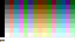
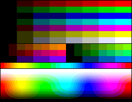
For each unique palette, an image color test chart and sample image (TrueColor original follows) rendered with that palette (without dithering) are given. Color charts for palettes that already exist in other articles are not shown here. The test chart shows the full 8-bits, 256 levels of the red, green and blue (RGB) primary colors and cyan, magenta and yellow complementary colors, along with a full 8-bits, 256 levels grayscale. Gradients of RGB intermediate colors (orange, lime green, sea green, sky blue, violet and fuchsia), and a full hue's spectrum are also present. Color charts are not gamma corrected.


Teletext
Teletext (a TV information retrieval service developed in 1976) uses a 3-bit RGB, 8-color palette.
Teletext has 40×25 characters. The top and bottom rows along with the first column are reserved. Every character cell has a background color and a text color. Graphics are built with a set of 2×3 pattern characters. Thus, the actual graphic surface is 78×69 blocky pixels.
A newer version of this standard defines a high resolution mode, but it is not supported by the vast majority of TV broadcasting networks nor TV sets manufacturers.
Apple
Apple II series


The Apple II series features a 16-color composite video palette, based on the YIQ color space used by the NTSC color TV system.[1][2]
15 different colors plus a duplicate gray can be achieved.[3]

Number — name Y Pb (rel.) Pr (rel.) Number — name Y Pb (rel.) Pr (rel.) 0 — black 0 0 0 8 — brown 0.25 −0.5 0 1 — magenta 0.25 0 0.5 9 — orange 0.5 −1 1 2 — dark blue 0.25 0.5 0 10 — grey #2 0.5 0 0 3 — purple 0.5 1 1 11 — pink 0.75 0 0.5 4 — dark green 0.25 0 −0.5 12 — green 0.5 −1 −1 5 — grey #1 0.5 0 0 13 — yellow 0.75 −0.5 0 6 — medium blue 0.5 1 −1 14 — aqua 0.75 0 −0.5 7 — light blue 0.75 0.5 0 15 — white 1 0 0
Atari 400/800/XL/XE


The early Atari 400 and 800 computers use a palette of 128 colours (a bit similar to the one used on the Atari 2600 console, and the Commodore 16 and Plus 4), using 4 bits for chrominance, and 3 for luminance. Screen modes may vary from 320×192 (384x240 with overscan) to 40×24, using 2 or 4 simultaneous colours, or 80×192 (96x240 with overscan) using 16 colours. After 2 years (late 1981) the CTIA graphics chip was replaced with the GTIA chip thus increasing the palette to 256 colours (CTIA and GTIA).
The ANTIC chip in the Atari 8-bit family computers (400, 800, XL and XE models) has an instruction set to run programs (called display list) which permits many more colours on the screen at once. There are a number of possible software-driven graphics modes. An example is the game Alternate Reality:The City (link to image).
Mattel Aquarius


The Mattel Aquarius computer has only a text mode with 40×24 characters, which graphic mode is obtained from low resolution blocks, providing an 80×72 resolution. The colour attribute area is also on this 40×24 characters area, and used from a pixel group of 2×3. The colours used in the palette are fixed and 16.[4]
Commodore
For all the following computers of this brand, the Pb and Pr coordinates for the YPbPr composite video colors are always the cosine and the sine, respectively, of angles multiple of 22.5 degrees (i.e. a quarter of 90°), as the engineerers were inspired by the NTSC color wheel, a radial way to figure out the Pb and Pr coordinates of points equidistant from the center of the chroma plane, the gray. You can find the formula needed to convert YPbPr to RGB at http://www.equasys.de/colorconversion.html
VIC-20


The Commodore VIC-20 features a MOS Technology VIC chip which produces a 16-color YPbPr composite video palette.[5]

Number — name Y Pb (rel.) Pr (rel.) Number — name Y Pb (rel.) Pr (rel.) 0 — black 0 0 0 8 — orange 0.5 −0.707 0.707 1 — white 1 0 0 9 — light orange 0.75 −0.707 0.707 2 — red 0.25 −0.383 0.924 10 — light red 0.5 −0.383 0.924 3 — cyan 0.75 0.383 −0.924 11 — light cyan* 1 0.383 −0.924 4 — purple 0.5 0.707 0.707 12 — light purple 0.75 0.707 0.707 5 — green 0.5 −0.707 −0.707 13 — light green 0.75 −0.707 −0.707 6 — blue 0.25 1 0 14 — light blue 0.5 1 0 7 — yellow 0.75 −1 0 15 — light yellow* 1 −1 0
Note: the colors marked with an asterisk (*) are out of the RGB gamut.
The palette lacks any intermediate shade of gray, and it has only four levels of luminance above the zero (black).
The VIC-20 lacks any true graphic mode, but a 22×11 text mode with 200 definable characters of 8×16 bits each arranged as a matrix of 20×10 characters is usually used instead, giving a 3:2(NTSC)/5:3(PAL) pixel aspect ratio, 160×160 pixels, 8-color "high-res mode" or a 3:1(NTSC)/10:3(PAL) pixel aspect ratio, 80×160 pixels, 10-color "multicolor mode".
- In the multicolor mode, a single pixel of every 4×8 block (a character cell) may have any of four colors: the background color, the auxiliary color (both shared for the entire screen and selectable among the entire palette), the same color as the overscan border (also a shared color) or a free foreground color, both selectable among the first eight colors of the palette.
- In the high-res mode, every 8×8 pixels can have the background color (shared for the entire screen) or a free foreground color, both selectable among the first eight colors of the palette.

C-64


The MOS Technology VIC-II is used in the Commodore 64 (and Commodore 128 in 40-column mode), and features a 16-color YPbPr composite video palette.[6]

Number — name Y Pb (rel.) Pr (rel.) Number — name Y Pb (rel.) Pr (rel.) 0 — black 0 0 0 8 — orange 0.375 −0.707 0.707 1 — white 1 0 0 9 — brown 0.25 −0.924 0.383 2 — red 0.313 −0.383 0.924 10 — light red 0.5 −0.383 0.924 3 — cyan 0.625 0.383 −0.924 11 — dark grey 0.313 0 0 4 — purple 0.375 0.707 0.707 12 — grey 0.469 0 0 5 — green 0.5 −0.707 −0.707 13 — light green 0.75 −0.707 −0.707 6 — blue 0.25 1 0 14 — light blue 0.469 1 0 7 — yellow 0.75 −1 0 15 — light grey 0.625 0 0
This palette is largely based on that of the VIC, but it substitutes three colors by three levels of gray. Also, there are more values for the luminance.
The Commodore 64 has two graphic modes: Multicolor and High Resolution.
- In the Multicolor 160×200, 16-color mode, every cell of 4×8, 2:1 aspect ratio pixels can have one of four colors: one shared with the entire screen, the two background and foreground colors of the corresponding text mode character, and one more color also stored in the color RAM area, all of them freely selectable among the entire palette.
- In the High Resolution 320×200, 16-color mode, every cell of 8×8 pixels can have one of the two background and foreground colors of the correspondent text mode character, both freely selectable among the entire palette.


What the palette looks like using the Color NTSC Sony CXA2025 decoder matrix.[7]
C-16 and Plus/4


The MOS Technology TED was used in the Commodore 16 and Commodore Plus/4. It has a palette of 121 YPbPr composite video colors[8] consisting of sixteen hues (including black and white) at eight luminance levels. Black is the same color at every luminance level, so there are not 128 different colors. On the Plus/4, twelve colors formed a "default" palette of sorts accessible through keyboard shortcuts;[9] these colors are underlined in the table below (RGB equivalents at a saturation level of 34%).
luma # 0 1 2 3 4 5 6 7 Y 0.125 0.25 0.375 0.5 0.625 0.75 0.875 1 hue # Pb (rel.) Pr (rel.) . . . . . . . . 0 — black 0 0 0,0 0,1 0,2 0,3 0,4 0,5 0,6 0,7 1 — white 0 0 1,0 1,1 1,2 1,3 1,4 1,5 1,6 1,7 2 — red −0.383 0.924 2,0 2,1 2,2 2,3 2,4 2,5 2,6* 2,7* 3 — cyan 0.383 −0.924 3,0* 3,1 3,2 3,3 3,4 3,5 3,6 3,7* 4 — purple 0.707 0.707 4,0* 4,1 4,2 4,3 4,4 4,5 4,6* 4,7* 5 — green −0.707 −0.707 5,0* 5,1 5,2 5,3 5,4 5,5 5,6* 5,7* 6 — blue 1 0 6,0 6,1 6,2 6,3 6,4 6,5* 6,6* 6,7* 7 — yellow −1 0 7,0* 7,1* 7,2 7,3 7,4 7,5 7,6 7,7* 8 — orange −0.707 0.707 8,0* 8,1 8,2 8,3 8,4 8,5 8,6* 8,7* 9 — brown −0.924 0.383 9,0* 9,1* 9,2 9,3 9,4 9,5 9,6 9,7* 10 — yellow-green −0.924 −0.383 10,0* 10,1* 10,2 10,3 10,4 10,5 10,6 10,7* 11 — pink 0 1 11,0 11,1 11,2 11,3 11,4 11,5 11,6* 11,7* 12 — blue-green 0 −1 12,0* 12,1 12,2 12,3 12,4 12,5 12,6 12,7* 13 — light blue 0.707 −0.707 13,0* 13,1 13,2 13,3 13,4 13,5 13,6* 13,7* 14 — dark blue 0.924 0.383 14,0 14,1 14,2 14,3 14,4 14,5* 14,6* 14,7* 15 — light green −0.383 −0.924 15,0* 15,1 15,2 15,3 15,4 15,5 15,6* 15,7*
Note: every YPbPr color marked with an asterisk (*) is out of the RGB gamut. This was intentionally done by the designers to achieve the maximum number of colors for composite video monitors.
Note: black has always a Y luminance level of 0, so ignore the column's header values.
The Commodore 16 and Plus/4 have two graphic modes very similar to those of the Commodore 64: Multicolor and High Resolution.
- In the Multicolor 160×200, 121-color mode, every cell of 4×8, 2:1 aspect ratio pixels can have one of four colors: two shared with the entire screen and the two background and foreground colors of the correspondent text mode character, all of them freely selectable among the entire 121-color palette (hue 0 to 15 and luminance 0 to 7 are set individually for any of them).
- In the High Resolution 320×200, 121-color mode, every cell of 8×8 pixels can have one of the two background and foreground colors of the corresponding text mode character, both freely selectable among the entire 121-color palette (again setting both the hue and the luminance).


Thomson
The most known display modes from Thomson computers (very popular in France) are 320×200, with 8×1 attribute cells with 2 colours. The TO7 can only display the 8 "saturated" colors. The TO7/70 and MO5 have the 16 color palette shown below as a fixed palette (just like on C64 or MSX1). On later models, these 16 colours can be chosen from 4096 and other video modes are available, removing the block constraints but reducing either the color count or the horizontal resolution.

BBC Micro


BBC Micro has 8 display modes, with resolutions like 640×256 (max. 2 colours), 320×256 (max. 4 colours) and 160×256 (max. 16 logical colours). No display modes have cell attribute clashes. The palette available has only 8 physical colours, plus a further 8 flashing colours (each being one of the eight non-flashing colours alternating with its physical complement), and the display modes can have 16, 4 or 2 simultaneous colours. There are three text display modes, and one of them is very similar to that used on Teletext or Minitel.
Sinclair
ZX Spectrum

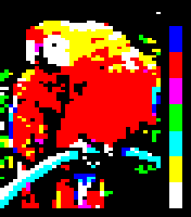
The ZX Spectrum (and compatible) computers use a variation of the 4-bit RGBI palette philosophy. This results in each of the colors of the 3-bit palette to have a basic and bright variant, with the exception of black.
The production method to generate the colors is having the eight basic 3-bit RGB combinations at maximum voltage level (the bright right column of the table below), black being the complete absence (0.0V for red plus 0.0V for green plus 0.0V for blue), and a second repertoire of the former but lowering the voltage levels to give lower brightness on screen (the basic left column). Original hardware lowered the video voltage values by about 84%[10] but common implementations on emulators (free of CRT gamma changes) usually adopt a 50% dimming to simulate the original effect, as reproduced here. Due to this, black is the same in both variants. The principle is the same one of the color test card of TV broadcasting stations.
Color number Binary value BRIGHT 0 BRIGHT 1 0 000 black black 1 001 basic blue bright blue 2 010 basic red bright red 3 011 basic magenta bright magenta 4 100 basic green bright green 5 101 basic cyan bright cyan 6 110 basic yellow bright yellow 7 111 basic white bright white
The attribute byte associated to every 8×8 pixels cell dedicates (from LSB to MSB): three bits for the background color; three bits for the foreground color; one bit for the bright variant for both, and one bit for the flashing effect (alternate foreground and background colors evenly in time). So the colors are not selectable as indices of a true palette (there are not color numbers 8 to 15).
The color numbers in the Sinclair BASIC are: 0 for black; 1 for blue; 2 for red; 3 for magenta; 4 for green; 5 for cyan; 6 for yellow and 7 for white. This follows the bit pattern to give the blue primary a weight of 1, the red primary a weight of 2 and the green primary a weight of 4 (see the table above).
The color numbers can be employed with the following statements to choose:
- BORDER n, the color for the surrounding area outside the pixel graphical area.
- PAPER n, the background (pixel bit value of 0) color for an 8×8 pixels cell.
- INK n, the foreground (pixel bit value of 1) color for an 8×8 pixels cell.
In the Sinclair BASIC, the BRIGHT statement selects the repertoire to be used for any 8×8 pixels cell (a color attribute area). BRIGHT 0 selects the basic variants and BRIGHT 1 selects the bright one. Both basic and bright variants cannot be selected for two colors in a single 8×8 pixels cell at a time, because only one bit in the attribute byte is devoted to this task. Also, the BRIGHT statement does not affect the border color, thus only the basic darker variants can be selected for this element.
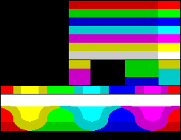
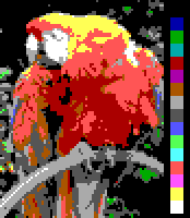
The following image simulates the parrot sample seen on a ZX Spectrum screen. No effort had been made to avoid the heavy attribute clash color square artifacts, and also it is not dithered (to see a better adaptation of the parrot image to the ZX Spectrum display, please visit the article ZX Spectrum graphic modes.)

SAM Coupé


The SAM Coupé has four display modes:
- Mode 1 provides 256×192 resolution, and is overall very similar to the ZX Spectrum display, including the 8×8 cell limit for 2 colours — except, all 16 logical colours can be chosen from a 128-colour master palette. As the palette is editable, the "bright" bit is now instead just the MSB out of four; or, effectively, used to choose between two 8-colour sub-palettes, of which only one can be used at a time within a single 8×8 cell. Naturally, these can be set by default to represent the regular 15-colour (7 colours × 2 shades, plus black) Spectrum palette for compatibility with legacy software. The memory consumption and layout is also identical to that of the Spectrum, with the 16-byte palette (or CLUT) held in a graphics hardware register.
- Mode 2 is similar to Mode 1, except it uses 8×1 cells instead of 8×8, and it employs a more easily modified linear memory map.
- Mode 3 provides 512×192 resolution, with a 4-colour, per-pixel (i.e. no attribute clash) palette available for each scanline — again chosen from a 128-colour master palette.
- Mode 4 is similar to Mode 3, but offers 256×192 resolution and a 16 colour (from 128) palette for each line. Both of these modes use a linear, non-planar (aka chunky / packed-pixel) memory bitmap, with 4 or 2 pixels per byte.
The 128 colour master palette used by the SAM Coupé is produced via a unique method — it effectively contains 2 groups of 64 "RGB" colours of mildly different intensity, and ultimately derived from a 512 colour space.[11] The closest equivalent in more popular and well-known machines would be the Commodore-Amiga's 64-colour "Extended HalfBrite" mode (with 32 explicitly set colours using 5 bitplanes, which are displayed with full or half brightness depending on the bit setting of a 6th plane).
Two bits are used for each of Red, Green and Blue and give a similar result to a normal 6-bit RGB palette (as seen with the IBM EGA or Sega Master System); the seventh bit encodes for "brightness", which has a similar but more subtle effect to the Spectrum, increasing the output of all three channels by half the intensity of the lower bits of the main six (in this way, it does make a genuine 128 colours — rather than what would have been 127 with "two blacks" and only a 7-level greyscale). The layout of the byte that encodes each colour is complicated and appears like a Spectrum colour nybble transferred to a full byte's width, and an extra RGB bit-triplet then prefixed to it, with the MSB left unused.
(Perhaps better explained as there being a "4" and "2" bit for each individual channel, separated within the byte, plus an interposed "1" booster bit that affects all three at once — many of the more subtle shades in the 512-colour palette, as compared to the 64-colour one, are available, but not all, as all three channels are required to be "even" or "odd" at the same time. So there are 8 shades of grey, and perceptually 8 shades of each primary (the presence of a dim glow from the other two/one channel(s) being harder to discern against the main one/two), but things become a little more complex beyond that)

Amstrad
CPC series


The Amstrad CPC 464/664/6128 series of computers generate the available palette with 3 levels (not bits) for every RGB primary. Thus, there are 27 different RGB combinations, from which 16 can be simultaneously displayed in low resolution mode, four in medium resolution mode and two in high resolution mode.[12]

0 – Black (5) 1 – Blue (0,14) 2 – Bright blue (6) 3 – Red 4 – Magenta 5 – Violet 6 – Bright red (3) 7 – Purple 8 – Bright magenta (7) 9 – Green 10 – Cyan (8) 11 – Sky blue (15) 12 – Yellow (9) 13 – Grey 14 – Pale blue (10) 15 – Orange 16 – Pink (11) 17 – Pale magenta 18 – Bright green (12) 19 – Sea green 20 – Bright cyan (2) 21 – Lime green 22 – Pale green (13) 23 – Pale cyan 24 – Bright yellow (1) 25 – Pale yellow 26 – Bright white (4)
The number in parentheses means the primary ink number for the Locomotive BASIC PEN, PAPER and INK statements (that is, "(1)" means ink #1 defaults to this color). Inks can also have a secondary color number, meaning they flash between two colors. By default, ink #14 alternates between colors 1 and 24 (blue and bright yellow) and ink #15 alternates between colors 11 and 16 (sky blue and pink). In addition, the paper defaults to ink #0 and the pen to ink #1, meaning bright yellow text on a blue background.
Simulations of actual images on the Amstrad's color monitor in each of the modes (160×200, 16 colors; 320×200, 4 colors and 640×200, 2 colors) follows. A cheaper green monochrome display was also available from the manufacturer; in this case, the colors are viewed as a 16-tone green scale, as shown in the last simulated image, as it interprets the overall brightness of the full colour signal, instead of only considering the green intensity as might, e.g., the Philips CM8833 line.


MSX systems
Original MSX


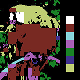
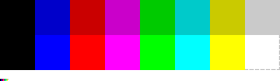
The MSX compatible computers feature a Texas Instruments TMS9918 chip which uses a proprietary 15-color YPbPr-encoded palette[13] plus a transparent color, intended to be used by the hardware sprites and simple video overlay. When used as an ordinary background color, it is rendered using the same color as the screen border.
Number — name Y Pb (rel.) Pr (rel.) Number — name Y Pb (rel.) Pr (rel.) 0 — transparent 0 0 0 8 — medium red 0.53 −0.377 0.868 1 — black 0 0 0 9 — light red 0.67 −0.377 0.868 2 — medium green 0.53 −0.509 −0.755 10 — dark yellow 0.73 −0.755 0.189 3 — light green 0.67 −0.377 −0.566 11 — light yellow 0.80 −0.566 0.189 4 — dark blue 0.40 1 −0.132 12 — dark green 0.47 −0.453 −0.642 5 — light blue 0.53 0.868 −0.075 13 — magenta 0.53 0.377 0.491 6 — dark red 0.47 −0.321 0.679 14 — gray 0.80 0 0 7 — cyan 0.73 0.434 −0.887 15 — white 1 0 0
There is no apparent logic in this color selection.
The MSX series has two text modes and two graphic modes. The MSX BASIC Screen 3 mode is a low-resolution 64×48-pixel mode with 15 colors, in which every pixel can be any of the 15 available colors. Screen mode 2 is a high-resolution 256×192-pixels mode with 15 colors, in which every eight consecutive pixels can be one of two out of the 15 available colors.


MSX2
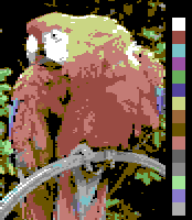
The MSX2 series features a Yamaha V9938 video chip, which manages a 9-bit RGB palette (512 colors) and has some extended graphic modes. Although its graphical capabilities are similar, or even better than of those of 16-bit personal computers, MSX2 and MSX2+ (see below) are pure 8-bit machines.
Screen mode 8 is a high-resolution 256×212-pixel mode with an 8-bit color depth, giving a palette of 256 colors.[14] From the MSB to LSB, there are three green bits, three red bits, and two blue bits. This mode uses half of the available colors overall, and can be considered a palette in its own right.


Screen modes 5 and 7 are high-resolution 256×212-pixel and 512×212-pixel modes, respectively, with a 16-color palette chosen from the available 512 colors. Each pixel can be any of the 16 selected colors.
Screen mode 6 is a 512×212-pixel mode with a 4-color palette chosen from the available 512 colors.
Here are simulated images for Screen modes 8, 5 and 6 respectively:


MSX2+
The MSX2+ series features a Yamaha V9958 video chip which manages a 15-bit RGB palette internally encoded in YJK (up to 19,268 different colors from the 32,768 theorically possible)[15] and has additional screen modes. Although its graphical capabilities are similar, or even better than of those of 16-bit personal computers, MSX2 (see above) and MSX2+ are pure 8-bit machines.
Screen modes 10 & 11 – technically the same but differentiated in MSX BASIC – are high-resolution 256×212-pixel modes with 12,499 YJK colours plus a 16-color palette. In this mode, the YJK technique encodes 16 levels of luminance into the four LSBs of each pixel and 64 levels of chroma, from −32 to +31, shared across every four consecutive pixels and stored in the three higher bits of the four pixels. If the fifth bit of the pixel is set, then the lower four bits of the pixel points to an index in the 16-color palette; otherwise, they specify the YJK luminance level of the pixel. The full YJK 12,499 color palette is as follows:


Screen mode 12 is similar to modes 10 and 11, but uses five bits to encode 32 levels of luminance for every pixel, thus it does not use an additional palette and, with YJK encoding, 19,268 different colors can be displayed simultaneously with 8-bit color depth.
In fact, YJK color encoding can be viewed as a lossy compression technique; in the RGB to YJK conversion, the average red and green levels are preserved, blue is subsampled. As a result of every four pixels sharing a chroma value, in mode 12 it is not possible to have vertical lines of a single color. This is only possible in modes 10 and 11 due to the additional 16-color direct palette. This can be used to mix 16 indexed colors with a rich colorful background, in what can be considered a primitive video overlay technique.
Here are simulated images for modes 10–12:


IBM PC/XT and compatible systems
- For the palettes of more advanced original IBM AT, IBM PS/2 and better PC compatibles hardware displays, please visit IBM PC-AT and compatible systems in the List of 16-bit computer hardware palettes article.
The original IBM PC launched in 1981 features an Intel 8088 CPU which was 8-bit data bus technology. It was offered with a Monochrome Display Adapter (MDA) or a Color Graphics Adapter (CGA). The MDA was a text mode-only display adapter, without any graphic ability beyond using the built-in code page 437 character set, and employed an original IBM green monochrome monitor; only black, green and highlighted green could be seen on its screen. Then, only the CGA had true graphic modes.
Despite the fact that the original IBM XT had a true 16-bit architecture, it already shipped both the original MDA or CGA display adapters, so this model is enumerated here too.
CGA


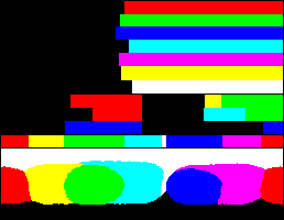
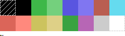
The Color Graphics Adapter (CGA) outputs what IBM called "digital RGB"[16] (that is, the R, G, B (and I) signals from the graphics card to the monitor can each only have two states: on or off). CGA supports a maximum of 16 colors. However, its 320×200 graphics mode is restricted to fixed palettes containing only four colors, and the 640×200 graphic mode is only two colors. 16 colours are only available in text mode or the "tweaked text" 160×100 mode. A different set of 16 colours is available in composite mode with composite monitor.
The full standard RGBI palette is a variant of the 4-bit RGBI schema. Although the RGBI signals have only two states, the CGA color monitor decodes them as if RGB signals had four levels. Darker colors are the basic RGB 2nd level signals except for brown, which is dark yellow with the level for the green component halved (1st level). Brighter colors are made by adding a uniform intensity one level signal to every RGB signal of the dark ones reaching the 3rd level (except dark gray which reaches only the 1st level), and in this case yellow is produced as if the brown were ordinary dark yellow.

0 — black 8 — dark gray 1 — low blue 9 — high blue 2 — low green 10 — high green 3 — low cyan 11 — high cyan 4 — low red 12 — high red 5 — low magenta 13 — high magenta 6 — brown 14 — yellow 7 — light gray 15 — white
The color numbers above are not arbitrary; they are based on the following bitmask:
Binary Base-Ten Color 1000 8 intense, high, or bright 0100 4 red 0010 2 green 0001 1 blue
A few earlier non-IBM compatible CGA monitors lack the circuitry to decode color numbers as of four levels internally, and they cannot show brown and dark gray. The above palette is displayed in such monitors as follows:
0 — black 8 — black 1 — low blue 9 — high blue 2 — low green 10 — high green 3 — low cyan 11 — high cyan 4 — low red 12 — high red 5 — low magenta 13 — high magenta 6 — low yellow 14 — yellow 7 — light gray 15 — white
- 16-color palette modes
- The only full 16-color BIOS modes of the CGA are the text mode 0 (40×25) and mode 2 (80×25). Disabling the flashing attribute effect and using the IBM 437 codepage block characters 220 (DCh) ▄ (bottom half) or 223 (DFh) ▀ (upper half), the mode 2 screen buffer provides an 80×50 quasi-graphic mode.
- Also, a tweak mode can be set in the CGA to give an extra, non-standard 160×100 pixels 16-color graphic mode.
- In these modes, the sample image would render approx. like this, respectively:

- 4-color palette modes
- In the 320×200 graphics mode, every pixel has two bits. A value of 0 is always a selectable background-plus-border color (with the same register and/or BIOS call used for the foreground color in the 640×200 graphic mode; black by default), and the three remaining values 1 to 3 are indices to one of the predefined color palette entries.
- The selection of a given fixed palette is a bit complex. There are two BIOS 320×200 graphic modes. The mode number 4 has enabled the composite color burst output (CRT Mode Control Register in 3D8H has cleared the bit 2), and the mode number 5 has it disabled (bit 2 set on the register). This gives two sets of palettes, one for "digital RGB" color monitors and one for monochrome composite video monitors, but the last has its own colors when viewed in a color monitor.
- The desired video mode, 4 or 5, can be set with the function 0h of the BIOS's INT 10h.
- For the BIOS mode 4, two palettes can be chosen: green-red-yellow and cyan-magenta-white (that is, the former plus the blue signal). The palette is selected with bit 5 of the CRT Color Selector Register in 3D9h. A value of 1 means the cyan-magenta-white palette (known as the "palette #1" because is the default for the mode 4), and 0 is the green-red-yellow (known as the "palette #2"). It can be set with the function 0Bh, subfunction 1, of the BIOS's INT 10h.
- The palette for the BIOS mode 5 is always cyan-red-white.
- In every of the 4 and 5 mode palettes, a low or high intensity can be chosen with the bit 4 of the CRT Color Selector Register in 3D9h. A value of 0 means the low intensity, and 1 means the high. No BIOS call exist to switch between the two intensity modes.

- Mode 4, palette #1, low intensity:
0 — [user-defined] 1 — cyan 2 — magenta 3 — light grey - The sixteen combinations with the background color are:
0 1 _ 0 1 _ 0 1 _ 0 1 * 0 1 _ 0 1 * 0 1 _ 0 1 * 2 3 _ 2 3 _ 2 3 _ 2 3 _ 2 3 _ 2 3 _ 2 3 _ 2 3 _ 0 1 _ 0 1 _ 0 1 _ 0 1 _ 0 1 _ 0 1 _ 0 1 _ 0 1 _ 2 3 _ 2 3 _ 2 3 _ 2 3 _ 2 3 _ 2 3 _ 2 3 _ 2 3 _ - (*) Useless due to the duplication of one of the colors.

- Mode 4, palette #1, high intensity:
0 — [user-defined] 1 — bright cyan 2 — bright magenta 3 — bright white - The sixteen combinations with the background color are:
0 1 _ 0 1 _ 0 1 _ 0 1 _ 0 1 _ 0 1 _ 0 1 _ 0 1 _ 2 3 _ 2 3 _ 2 3 _ 2 3 _ 2 3 _ 2 3 _ 2 3 _ 2 3 _ 0 1 _ 0 1 _ 0 1 _ 0 1 * 0 1 _ 0 1 * 0 1 _ 0 1 * 2 3 _ 2 3 _ 2 3 _ 2 3 _ 2 3 _ 2 3 _ 2 3 _ 2 3 _ - (*) Useless due to the duplication of one of the colors.

- Mode 4, palette #2, low intensity:
0 — [user-defined] 1 — green 2 — red 3 — brown - The sixteen combinations with the background color are:
0 1 _ 0 1 _ 0 1 * 0 1 _ 0 1 * 0 1 _ 0 1 * 0 1 _ 2 3 _ 2 3 _ 2 3 _ 2 3 _ 2 3 _ 2 3 _ 2 3 _ 2 3 _ 0 1 _ 0 1 _ 0 1 _ 0 1 _ 0 1 _ 0 1 _ 0 1 _ 0 1 _ 2 3 _ 2 3 _ 2 3 _ 2 3 _ 2 3 _ 2 3 _ 2 3 _ 2 3 _ - (*) Useless due to the duplication of one of the colors.

- Mode 4, palette #2, high intensity:
0 — [user-defined] 1 — bright green 2 — bright red 3 — yellow - The sixteen combinations with the background color are:
0 1 _ 0 1 _ 0 1 _ 0 1 _ 0 1 _ 0 1 _ 0 1 _ 0 1 _ 2 3 _ 2 3 _ 2 3 _ 2 3 _ 2 3 _ 2 3 _ 2 3 _ 2 3 _ 0 1 _ 0 1 _ 0 1 * 0 1 _ 0 1 * 0 1 _ 0 1 * 0 1 _ 2 3 _ 2 3 _ 2 3 _ 2 3 _ 2 3 _ 2 3 _ 2 3 _ 2 3 _ - (*) Useless due to the duplication of one of the colors.

- Mode 5, low intensity:
0 — [user-defined] 1 — cyan 2 — red 3 — light grey - The sixteen combinations with the background color are:
0 1 _ 0 1 _ 0 1 _ 0 1 * 0 1 * 0 1 _ 0 1 _ 0 1 * 2 3 _ 2 3 _ 2 3 _ 2 3 _ 2 3 _ 2 3 _ 2 3 _ 2 3 _ 0 1 _ 0 1 _ 0 1 _ 0 1 _ 0 1 _ 0 1 _ 0 1 _ 0 1 _ 2 3 _ 2 3 _ 2 3 _ 2 3 _ 2 3 _ 2 3 _ 2 3 _ 2 3 _ - (*) Useless due to the duplication of one of the colors.

- Mode 5, high intensity:
0 — [user-defined] 1 — bright cyan 2 — bright red 3 — white - The sixteen combinations with the background color are:
0 1 _ 0 1 _ 0 1 _ 0 1 _ 0 1 _ 0 1 _ 0 1 _ 0 1 _ 2 3 _ 2 3 _ 2 3 _ 2 3 _ 2 3 _ 2 3 _ 2 3 _ 2 3 _ 0 1 _ 0 1 _ 0 1 _ 0 1 * 0 1 * 0 1 _ 0 1 _ 0 1 * 2 3 _ 2 3 _ 2 3 _ 2 3 _ 2 3 _ 2 3 _ 2 3 _ 2 3 _ - (*) Useless due to the duplication of one of the colors.
- When viewed in a monochrome composite monitor, the mode 5 palettes above are shown as a (more or less brighter) 2-bit grayscale palette:

- 2-color palette mode

- In the 640×200 graphic mode (BIOS mode number 6), every pixel has only a single bit. A value of 0 is always black, while a value of 1 is the color set in the bits 0 to 3 (bit3=I, bit2=R, bit1=G, bit0=B) of the CRT Color Selector Register (in 3D9h). The foreground color can be set with a call to the function 0Bh of the BIOS's INT 10h. The default foreground color is white.
0 — black 1 — [user-defined] - The sixteen combinations are:
0 1 _ 0 1 _ 0 1 _ 0 1 _ 0 1 _ 0 1 _ 0 1 _ 0 1 _ 0 1 _ 0 1 _ 0 1 _ 0 1 _ 0 1 _ 0 1 _ 0 1 _ 0 1 _
PCjr and Tandy 1000 series
Although not fully compatible with the original IBM PC, the IBM PCjr (and near compatible Tandy 1000 series) feature a graphic chip known as "Video Gate Array" (not to be confused with the most widely known Video Graphics Array, despite the fact that both share the same acronym VGA), which is able to show all 16 CGA colors simultaneously on screen in the extended low-res graphic modes 160×100 and 160×200, and mid-res 320×200. This graphic adapter is better known as Tandy Graphics Adapter. Here is the sample image using their exclusive low-res 160×200 mode, 2:1 pixel ratio:

They also support an additional high-resolution 640×200 mode using any of the same 4-color mid-res 320×200 CGA palettes (see the CGA section above). Finally, all extended PCjr/Tandy 1000 graphics modes could reassign any color index to any palette entry, for color cycling effects.
See also
- List of 16-bit computer hardware palettes
- List of videogame consoles palettes
- List of color palettes
- Palette (computing)
- Indexed color
- Color Lookup Table
- Color depth
- Computer display
- List of home computers by video hardware
Notes
- ↑ "The Laboratorium : Why Did the Apple II Have Six Colors?". laboratorium.net.
- ↑ http://www.downloads.reactivemicro.com/Public/Users/Grant_Stockley/Apple2MoreColorsBYTEJun1979.pdf
- ↑ http://apple-2.com/pdf/bbfront.png
- ↑ http://atariage.com/forums/uploads/monthly_07_2014/post-3819-0-00736800-1405189983.jpg
- ↑ "The 6561 VIC chip". 090420 fpgaarcade.com
- ↑ Philip 'Pepto' Timmermann (12 March 2001). "All you ever wanted to know about the colors of the commodore 64". pepto.de.
- ↑ "C64 Emulator Palette from my NTSC 1702 - Page 2 - Commodore 64 (C64) Forum". lemon64.com.
- ↑ Commodore Hacking #12 : Talking to TED
- ↑ Color codes
- ↑ Smith, Chris. "Spectrum Clone Design Blog". zxdesign.info.
- ↑ Cooke, Simon; et al. (1994). "The Graphics Hardware" (PDF). The Unofficial SAM Coupé Technical Manual (sampler edition). Σntropy. pp. 16–20. Retrieved 5 February 2013.
- ↑ "The Amstrad CPC Firmware Guide"
- ↑ VDP Registers 00h-07h: Basic MSX1/MSX2 Video Registers from "Portar MSX Tech Doc"
- ↑ Bits M1-M5 of VDP register 0 and 1: Video Screen modes, Screen 8 from "Portar MSX Tech Doc"
- ↑ "The MSX Plaza". msx-plaza.eu.
- ↑ Richard Wilton, Programmer's Guide to PC & PS/2 VIDEO SYSTEMS, 1987, Microsoft Press.