NOR gate
| INPUT | OUTPUT | |
| A | B | A NOR B |
| 0 | 0 | 1 |
| 0 | 1 | 0 |
| 1 | 0 | 0 |
| 1 | 1 | 0 |
The NOR gate is a digital logic gate that implements logical NOR - it behaves according to the truth table to the right. A HIGH output (1) results if both the inputs to the gate are LOW (0); if one or both input is HIGH (1), a LOW output (0) results. NOR is the result of the negation of the OR operator. It can also be seen as an AND gate with all the inputs inverted. NOR is a functionally complete operation—NOR gates can be combined to generate any other logical function. it shares this property with the NAND gate. By contrast, the OR operator is monotonic as it can only change LOW to HIGH but not vice versa.
In most, but not all, circuit implementations, the negation comes for free—including CMOS and TTL. In such logic families, OR is the more complicated operation; it may use a NOR followed by a NOT. A significant exception is some forms of the domino logic family.
The original Apollo Guidance Computer used 4,100 ICs, each one containing only a single 3-input NOR gate.
Symbols
There are three symbols for NOR gates: the American (ANSI or 'military') symbol and the IEC ('European' or 'rectangular') symbol, as well as the deprecated DIN symbol. For more information see Logic Gate Symbols. The ANSI symbol for the NOR gate is a standard OR gate with an inversion bubble connected.
 |
 |
 |
| MIL/ANSI Symbol | IEC Symbol | DIN Symbol |

Hardware description and pinout
NOR Gates are basic logic gates, and as such they are recognised in TTL and CMOS ICs. The standard, 4000 series, CMOS IC is the 4001, which includes four independent, two-input, NOR gates. The pinout diagram is as follows:
 Pinout Diagram of a 4001 Quad NOR DIP-format IC |
1 Input A1 2 Input B1 3 Output Q1 4 Output Q2 5 Input B2 6 Input A2 7 Vss 8 Input A3 9 Input B3 10 Output Q3 11 Output Q4 12 Input B4 13 Input A4 14 Vdd |
Availability
These devices are available from most semiconductor manufacturers such as Fairchild Semiconductor, Philips or Texas Instruments. These are usually available in both through-hole DIP and SOIC format. Datasheets are readily available in most datasheet databases.
In the popular CMOS and TTL logic families, NOR gates with up to 8 inputs are available:
- CMOS
- 4001: Quad 2-input NOR gate
- 4025: Triple 3-input NOR gate
- 4002: Dual 4-input NOR gate
- 4078: Single 8-input NOR gate
- TTL
- 7402: Quad 2-input NOR gate
- 7427: Triple 3-input NOR gate
- 7425: Dual 4-input NOR gate (with strobe, obsolete)
- 74260: Dual 5-Input NOR Gate
- 744078: Single 8-input NOR Gate
In the older RTL and ECL families, NOR gates were efficient and most commonly used.
Implementations
 |
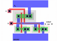 The physical layout of a CMOS NOR |
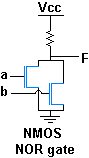
The diagrams above show the construction of a 2-input NOR gate using NMOS logic circuitry. If either of the inputs is high, the corresponding N-channel MOSFET is turned on and the output is pulled low; otherwise the output is pulled high through the pull-up resistor.
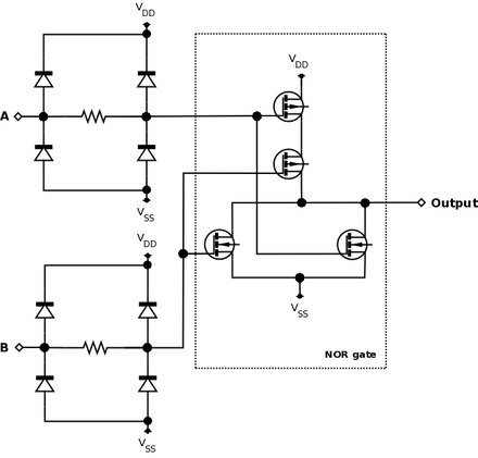
The diagram below shows a 2-input NOR gate using CMOS technology. The diodes and resistors on the inputs are to protect the CMOS components from damage due to electrostatic discharge (ESD) and play no part in the logical function of the circuit.
Alternatives
If no specific NOR gates are available, one can be made from NAND gates, because NAND and NOR gates are considered the "universal gates", meaning that they can be used to make all the other gates.[1]
| NAND Construction |
|---|
 |
See also
- AND gate
- OR gate
- NOT gate
- NAND gate
- XOR gate
- XNOR gate
- Boolean algebra (logic)
- Logic gates
- NOR logic
References
- ↑ Mano, M. Morris and Charles R. Kime. Logic and Computer Design Fundamentals, Third Edition. Prentice Hall, 2004. p. 73.
External links
- Interactive NOR gate, Displays the logic simulation of the NOR Gate.
| Wikimedia Commons has media related to NOR gates. |
 | ||


