Pulse-density modulation
Pulse-density modulation, or PDM, is a form of modulation used to represent an analog signal with a binary signal. In a PDM signal, specific amplitude values are not encoded into codewords of pulses of different weight as they would be in pulse-code modulation (PCM). Instead, it is the relative density of the pulses that corresponds to the analog signal's amplitude. The output of a 1-bit DAC is the same as the PDM encoding of the signal. Pulse-width modulation (PWM) is a special case of PDM where the switching frequency is fixed and all the pulses corresponding to one sample are contiguous in the digital signal. For a 50% voltage with a resolution of 8-bits, a PWM waveform will turn on for 128 clock cycles and then off for the remaining 128 cycles. With PDM and the same clock rate the signal would alternate between on and off every other cycle. The average is 50% for both waveforms, but the PDM signal switches more often. For 100% or 0% level, they are the same.
Description
In a pulse-density modulation bitstream a 1 corresponds to a pulse of positive polarity (+A) and a 0 corresponds to a pulse of negative polarity (-A). Mathematically, this can be represented as:
![x[n]=-A(-1)^{{a[n]}}\](../I/m/ae63d3004ad8d9f5009670b7db21283461592b70.svg)
- where x[n] is the bipolar bitstream (either -A or +A) and a[n] is the corresponding binary bitstream (either 0 or 1).
A run consisting of all 1s would correspond to the maximum (positive) amplitude value, all 0s would correspond to the minimum (negative) amplitude value, and alternating 1s and 0s would correspond to a zero amplitude value. The continuous amplitude waveform is recovered by low-pass filtering the bipolar PDM bitstream.
Examples
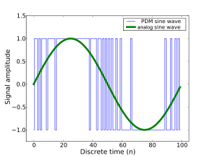
A single period of the trigonometric sine function, sampled 100 times and represented as a PDM bitstream, is:
0101011011110111111111111111111111011111101101101010100100100000010000000000000000000001000010010101
Two periods of a higher frequency sine wave would appear as:
0101101111111111111101101010010000000000000100010011011101111111111111011010100100000000000000100101
In pulse-density modulation, a high density of 1s occurs at the peaks of the sine wave, while a low density of 1s occurs at the troughs of the sine wave.
Analog-to-digital conversion
A PDM bitstream is encoded from an analog signal through the process of delta-sigma modulation. This process uses a one bit quantizer that produces either a 1 or 0 depending on the amplitude of the analog signal. A 1 or 0 corresponds to a signal that is all the way up or all the way down, respectively. Because in the real world, analog signals are rarely all the way in one direction, there is a quantization error, the difference between the 1 or 0 and the actual amplitude it represents. This error is fed back negatively in the ΔΣ process loop. In this way, every error successively influences every other quantization measurement and its error. This has the effect of averaging out the quantization error.
Digital-to-analog conversion
The process of decoding a PDM signal into an analog one is simple: one only has to pass the PDM signal through a low-pass filter. This works because the function of a low-pass filter is essentially to average the signal. The average amplitude of pulses is measured by the density of those pulses over time, thus a low pass filter is the only step required in the decoding process.
Relationship to biology
Notably, one of the ways animal nervous systems represent sensory and other information is through rate coding whereby the magnitude of the signal is related to the rate of firing of the sensory neuron. In direct analogy, each neural event – called an action potential – represents one bit (pulse), with the rate of firing of the neuron representing the pulse density.
Algorithm
A digital model of pulse-density modulation can be obtained from a digital model of the delta-sigma modulator. Consider a signal in the discrete time domain as the input to a first-order delta-sigma modulator, with the output. In the discrete frequency domain, the delta-sigma modulator's operation is represented by
![x[n]](../I/m/864cbbefbdcb55af4d9390911de1bf70167c4a3d.svg)
![y[n]](../I/m/305428e6d1fb59cd0163a7a96ace52292a262afa.svg)

Rearranging terms, we obtain
![Y(z)=E(z)+\left[X(z)-Y(z)z^{{-1}}\right]\left({\frac {1}{1-z^{{-1}}}}\right).](../I/m/6dbd0060a6fb18a273c3ceccc9efc396b81dacb3.svg)
Here, is the frequency-domain quantization error of the delta-sigma modulator. The factor represents a high-pass filter, so it is clear that contributes less to the output at low frequencies, and more at high frequencies. This demonstrates the noise shaping effect of the delta-sigma modulator: the quantization noise is "pushed" out of the low frequencies up into the high-frequency range.


Using the inverse Z-transform, we may convert this into a difference equation relating the input of the delta-sigma modulator to its output in the discrete time domain,
![y[n]=x[n]+e[n]-e[n-1]](../I/m/31f7cce1628151beed577c42349b8b55c834b8b5.svg)
There are two additional constraints to consider: first, at each step the output sample is chosen so as to minimize the "running" quantization error . Second, is represented as a single bit, meaning it can take on only two values. We choose for convenience, allowing us to write
![e[n]](../I/m/9333d516ef86093cecb2ccbbc8097e5136758c0d.svg)
![y[n]=\pm 1](../I/m/52ce163ec18b4dcf10bd31d2be0bade273fb179a.svg)
![{\displaystyle {\begin{aligned}y[n]&=\operatorname {sgn}(x[n]-e[n-1])\\\\&={\begin{cases}+1&x[n]>e[n-1]\\-1&x[n]<e[n-1]\end{cases}}\\\\&=(x[n]-e[n-1])+e[n]\\\end{aligned}}}](../I/m/e23539fd4a54a06104ca313505c393cf2f13d1ca.svg)
![{\displaystyle e[n]\leftarrow y[n]-(x[n]-e[n-1])=\operatorname {sgn}(x[n]-e[n-1])-(x[n]-e[n-1])}](../I/m/7082287ef2981319c0c3ecb9a47db48889856f0d.svg)
This, finally, gives a formula for the output sample in terms of the input sample . The quantization error of each sample is fed back into the input for the following sample.
The following pseudo-code implements this algorithm to convert a pulse-code modulation signal into a PDM signal:
// Encode samples into pulse-density modulation
// using a first-order sigma-delta modulator

function pdm(real[0..s] x)
  var int[0..s] y
  var real[-1..s] qe

  qe[-1] := 0                  // initial running error is zero

  for n from 0 to s
      if x[n] >= qe[n-1]
          y[n] := 1
      else
          y[n] := -1
      qe[n] := y[n] - x[n] + qe[n-1]

  return y, qe                 // return output and running error
Applications
PDM is the encoding used in Sony's Super Audio CD (SACD) format, under the name Direct Stream Digital.
Some systems transmit PDM stereo audio over a single data wire. The rising edge of the master clock indicates a bit from the left channel, while the falling edge of the master clock indicates a bit from the right channel.[1][2][3]
See also
References
- ↑ Thomas Kite. "Understanding PDM Digital Audio" (PDF). 2012. The "PDM Microphones" section on p. 6.
- ↑ Maxim Integrated. "PDM Input Class D Audio Power Amplifier" (PDF). 2013. Figure 1 on p. 5; and the "Digital Audio Interface" section on p. 13.
- ↑ Akustica. "AKU230 Digital, CMOS MEMS Microphone" (PDF). 2012. p. 5.
External links
- 1-bit A/D and D/A Converters – Discusses delta modulation, PDM (also known as Sigma-delta modulation or SDM), and relationships to Pulse-code modulation (PCM)