Loading coil
A loading coil or load coil is an inductor that is inserted into an electronic circuit to increase its inductance. A loading coil is not a transformer as it does not provide coupling to another circuit. The term originated in the 19th century for inductors used to prevent signal distortion in long-distance telegraph transmission cables. The term is also used for inductors in radio antennas, or between the antenna and its feedline, to make an electrically short antenna resonant at its operating frequency.
Loading coils are historically also known as Pupin coils after Mihajlo Pupin, especially when used for the Heaviside condition and the process of inserting them is sometimes called pupinization.
The concept of loading coils was discovered by Oliver Heaviside in studying the problem of slow signalling speed of the first transatlantic telegraph cable in the 1860s. He concluded additional inductance was required to prevent amplitude and time delay distortion of the transmitted signal. The mathematical condition for distortion-free transmission is known as the Heaviside condition. Previous telegraph lines were overland or shorter and hence had less delay, and the need for extra inductance was not as great. Submarine communications cables are particularly subject to the problem, but early 20th century installations using balanced pairs were often continuously loaded with iron wire or tape rather than discretely with loading coils, which avoided the sealing problem.
Applications

Telephone lines

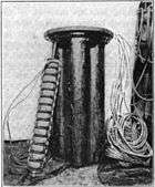
A common application of loading coils is to improve the voice-frequency amplitude response characteristics of the twisted balanced pairs in a telephone cable. Because twisted pair is a balanced format, half the loading coil must be inserted in each leg of the pair to maintain the balance. It is common for both these windings to be formed on the same core. This increases the flux linkages, without which the number of turns on the coil would need to be increased.
Loading coils inserted periodically in series with a pair of wires reduce the attenuation at the higher voice frequencies up to the cutoff frequency of the low-pass filter formed by the inductance of the coils (plus the distributed inductance of the wires) and the distributed capacitance between the wires. Above the cutoff frequency, attenuation increases rapidly. The shorter the distance between the coils, the higher the cut-off frequency.
It should be emphasised that the cutoff effect is an artifact of using lumped inductors. With loading methods using continuous distributed inductance there is no cutoff.
Without loading coils, the line response is dominated by the resistance and capacitance of the line with the attenuation gently increasing with frequency. With loading coils of exactly the right inductance, neither capacitance nor inductance dominate: the response is flat, waveforms are undistorted and the characteristic impedance is resistive up to the cutoff frequency. The coincidental formation of an audio frequency filter is also beneficial in that noise is reduced.
DSL
When loading coils are in place, signal attenuation remains low for signals within the passband of the transmission line but increases rapidly for frequencies above the audio cutoff frequency. Thus, if the pair is subsequently reused to support applications that require higher frequencies (such as analog or digital carrier systems or DSL), any loading coils that were present on the line must be removed or replaced with ones which are transparent to DSL. Using coils with parallel capacitors will form a filter with the topology of an m-derived filter and a band of frequencies above the cut-off will also be passed.
If the coils are not removed, and the subscriber is an extended distance (e.g. over 4 miles or 6.4 km) from the Central Office, DSL can not be supported. This sometimes happens in dense, growing areas such as Southern California in the late 1990s and early 21st century.

Carrier systems
American early and middle 20th century telephone cables had load coils at intervals of a mile (1.61 km), usually in coil cases holding many. The coils had to be removed to pass higher frequencies, but the coil cases provided convenient places for repeaters of digital T-carrier systems, which could then transmit a 1.5 Mbit/s signal that distance. Due to narrower streets and higher cost of copper, European cables had thinner wires and used closer spacing. Intervals of a kilometer allowed European systems to carry 2 Mbit/s.
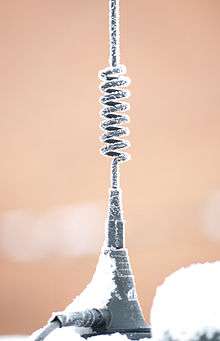
Radio antenna
Another type of loading coil is used in radio antennas. Monopole and dipole radio antennas are designed to act as resonators for radio waves; the power from the transmitter, applied to the antenna through the antenna's transmission line, excites standing waves of voltage and current in the antenna element. To be resonant, the antenna must have a physical length of one quarter of the wavelength of the radio waves used (or a multiple of that length). At resonance the antenna acts electrically as a pure resistance, absorbing all the power applied to it from the transmitter.
In many cases for practical reasons it is necessary to make the antenna shorter than the resonant length. An antenna shorter than a quarter wavelength presents capacitive reactance to the transmission line. Some of the applied power is reflected back into the transmission line and travels back toward the transmitter. This causes standing waves on the transmission line (a standing wave ratio (SWR) greater than one) which waste energy, and can even overheat the transmitter.
So to make an electrically short antenna resonant, an inductor called a loading coil is inserted in series with the antenna. The inductive reactance of the coil is equal and opposite to, and cancels, the capacitive reactance of the antenna, so the loaded antenna presents a pure resistance to the transmission line, preventing energy from being reflected.
The loading coil is usually inserted at the base of the antenna, between it and the transmission line (base loading), but sometimes it is inserted in the center of the antenna element itself (center loading).
Campbell equation
The Campbell equation is a relationship due to George Ashley Campbell for predicting the propagation constant of a loaded line. It is stated as;[1]

- where,
- is the propagation constant of the unloaded line
- is the propagation constant of the loaded line
- is the interval between coils on the loaded line
- is the impedance of a loading coil and
- is the characteristic impedance of the unloaded line.


A more engineer friendly rule of thumb is that the approximate requirement for spacing loading coils is ten coils per wavelength of the maximum frequency being transmitted.[2] This approximation can be arrived at by treating the loaded line as a constant k filter and applying image filter theory to it. From basic image filter theory the angular cutoff frequency and the characteristic impedance of a low-pass constant k filter are given by;
- and,


- where and are the half section element values.


From these basic equations the necessary loading coil inductance and coil spacing can be found;
- and,


- where C is the capacitance per unit length of the line.
Expressing this in terms of number of coils per cutoff wavelength yields;

- where v is the velocity of propagation of the cable in question.
The phenomenon of cutoff whereby frequencies above the cutoff frequency are not transmitted is an undesirable side effect of loading coils (although it proved highly useful in the development of filters). Cutoff is avoided by the use of continuous loading since it arises from the lumped nature of the loading coils.[3]
History
Oliver Heaviside
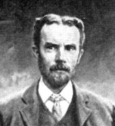
The origin of the loading coil can be found in the work of Oliver Heaviside on the theory of transmission lines. Heaviside (1881) represented the line as a network of infinitesimally small circuit elements. By applying his operational calculus to the analysis of this network he discovered (1887) what has become known as the Heaviside condition.[4][5] This is the condition that must be fulfilled in order for a transmission line to be free from distortion. The Heaviside condition is that the series impedance, Z, must be proportional to the shunt admittance, Y, at all frequencies. In terms of the primary line coefficients the condition is:

- where;
- is the series resistance of the line per unit length
- is the series self-inductance of the line per unit length
- is the shunt leakage conductance of the line insulator per unit length
- is the shunt capacitance between the line conductors per unit length


Heaviside was aware that this condition was not met in the practical telegraph cables in use in his day. In general, a real cable would have,

This is mainly due to the low value of leakage through the cable insulator, which is even more pronounced in modern cables which have better insulators than in Heaviside's day. In order to meet the condition, the choices are therefore to try to increase G or L or to decrease R or C. Decreasing R requires larger conductors. Copper was already in use in telegraph cables and this is the very best conductor available short of using silver. Decreasing R means using more copper and a more expensive cable. Decreasing C would also mean a larger cable (although not necessarily more copper). Increasing G is highly undesirable; while it would reduce distortion, it would at the same time increase the signal loss. Heaviside considered, but rejected, this possibility which left him with the strategy of increasing L as the way to reduce distortion.[6]
Heaviside immediately (1887) proposed several methods of increasing the inductance, including spacing the conductors further apart and loading the insulator with iron dust. Finally, Heaviside made the proposal (1893) to use discrete inductors at intervals along the line.[7] However, he never succeeded in persuading the British GPO to take up the idea. Brittain attributes this to Heaviside's failure to provide engineering details on the size and spacing of the coils for particular cable parameters. Heaviside's eccentric character and setting himself apart from the establishment may also have played a part in their ignoring of him.[8]
John Stone
John S. Stone worked for the American Telephone & Telegraph Company (AT&T) and was the first to attempt to apply Heaviside's ideas to real telecommunications. Stone's idea (1896) was to use a bimetallic iron-copper cable which he had patented.[9] This cable of Stone's would increase the line inductance due to the iron content and had the potential to meet the Heaviside condition. However, Stone left the company in 1899 and the idea was never implemented.[10] Stone's cable was an example of continuous loading, a principle that was eventually put into practice is other forms, see for instance Krarup cable later in this article.
George Campbell
George Campbell was another AT&T engineer working in their Boston facility. Campbell was tasked with continuing the investigation into Stone's bimetallic cable, but soon abandoned it in favour of the loading coil. His was an independent discovery, Campbell was aware of Heaviside's work in discovering the Heaviside condition, but unaware of Heaviside's suggestion of using loading coils to enable a line to meet it. The motivation for the change of direction was Campbell's limited budget.
Campbell was struggling to set up a practical demonstration over a real telephone route with the budget he had been allocated. After considering that his artificial line simulators used lumped components rather than the distributed quantities found in a real line, he wondered if he could not insert the inductance with lumped components instead of using Stone's distributed line. When his calculations showed that the manholes on telephone routes were sufficiently close together to be able to insert the loading coils without the expense of either having to dig up the route or lay in new cables he changed to this new plan.[11] The very first demonstration of loading coils on a telephone cable was on a 46-mile length of the so-called Pittsburgh cable (the test was actually in Boston, the cable had previously been used for testing in Pittsburgh) on 6 September 1899 carried out by Campbell himself and his assistant.[12] The first telephone cable using loaded lines put into public service was between Jamaica Plain and West Newton in Boston on 18 May 1900.[13]
Campbell's work on loading coils provided the theoretical basis for his subsequent work on filters which proved to be so important for frequency-division multiplexing. The cut-off phenomena of loading coils, an undesirable side-effect, can be exploited to produce a desirable filter frequency response.[14][15]
Michael Pupin

Michael Pupin, inventor and Serbian immigrant to the USA, also played a part in the story of loading coils. Pupin filed a rival patent to the one of Campbell's.[16] This patent of Pupin's dates from 1899. There is an earlier patent[17] (1894, filed December 1893) which is sometimes cited as Pupin's loading coil patent but is, in fact, something different. The confusion is easy to understand, Pupin himself claims that he first thought of the idea of loading coils while climbing a mountain in 1894,[18] although there is nothing from him published at that time.[19]
Pupin's 1894 patent "loads" the line with capacitors rather than inductors, a scheme that has been criticised as being theoretically flawed[20] and never put into practice. To add to the confusion, one variant of the capacitor scheme proposed by Pupin does indeed have coils. However, these are not intended to compensate the line in any way. They are there merely to restore DC continuity to the line so that it may be tested with regular equipment. Pupin states that the inductance is to be so large that it will block all AC signals above 50 Hz.[21] Consequently, only the capacitor is adding any significant impedance to the line and "the coils will not exercise any material influence on the results before noted".[22]
Legal battle
Heaviside never patented his idea; indeed, he took no commercial advantage of any of his work.[23] Despite the legal disputes surrounding this invention, it is unquestionable that Campbell was the first to actually construct a telephone circuit using loading coils.[24] There also can be little doubt that Heaviside was the first to publish and many would dispute Pupin's priority.[25]
AT&T fought a legal battle with Pupin over his claim. Pupin was first to patent but Campbell had already conducted practical demonstrations before Pupin had even filed his patent (December 1899).[26] Campbell's delay in filing was due to the slow internal machinations of AT&T.[27]
However, AT&T foolishly deleted from Campbell's proposed patent application all the tables and graphs detailing the exact value of inductance that would be required before the patent was submitted.[28] Since Pupin's patent contained a (less accurate) formula, AT&T was open to claims of incomplete disclosure. Fearing that there was a risk that the battle would end with the invention being declared unpatentable due to Heaviside's prior publication, they decided to desist from the challenge and buy an option on Pupin's patent for a yearly fee so that AT&T would control both patents. By January 1901 Pupin had been paid $200,000 ($13 million in 2011[29]) and by 1917, when the AT&T monopoly ended and payments ceased, he had received a total of $455,000 ($25 million in 2011[29]).[30]
Benefit to AT&T
The invention was of enormous value to AT&T. Telephone cables could now be used to twice the distance previously possible, or alternatively, a cable of half the previous quality (and cost) could be used over the same distance. When considering whether to allow Campbell to go ahead with the demonstration, their engineers had estimated that they stood to save $700,000 in new installation costs in New York and New Jersey alone.[31] It has been estimated that AT&T saved $100 million in the first quarter of the 20th century.[32][33] Heaviside, who began it all, came away with nothing. He was offered a token payment but would not accept, wanting the credit for his work. He remarked ironically that if his prior publication had been admitted it would "interfere . . . with the flow of dollars in the proper direction . . .".[34]
Krarup cable
Loading coils were not without their problems. In heavy submarine cables, loading coils were difficult to lay. Discontinuities where the coils were installed caused stresses in the cable during laying. Without great care, the cable might part and would be difficult to repair. A second problem was that the material science of the time had difficulties sealing the joint between coil and cable against ingress of seawater. When this occurred the cable was ruined.[35]
A Danish engineer, Carl Emil Krarup, invented a form of continuously loaded cable which solved these problems and the cable is named for him. Krarup cable has iron wires continuously wound around the central copper conductor with adjacent turns in contact with each other. This cable was the first use of continuous loading on any telecommunication cable.[36] In 1902, Krarup both wrote his paper on this subject and saw the installation of the first cable between Helsingør (Denmark) and Helsingborg (Sweden).[37]
Permalloy cable

Even though the Krarup cable added inductance to the line, this was insufficient to meet the Heaviside condition. AT&T searched for a better material with higher magnetic permeability. In 1914, Gustav Elmen discovered permalloy, a magnetic nickel-iron annealed alloy. In c. 1915, Oliver E. Buckley, H. D. Arnold, and Elmen, all at Bell Labs, greatly improved transmission speeds by suggesting a method of constructing submarine communications cable using permalloy tape wrapped around the copper conductors.[38]
The cable was tested in a trial in Bermuda in 1923. The first permalloy cable placed in service connected New York City and Horta (Azores) in September 1924.[38] Permalloy cable enabled signalling speed on submarine telegraph cables to be increased to 400 words/min at a time when 40 words/min was considered good.[39] The first transatlantic cable achieved only two words/min.[40]
Mu-metal cable

Mu-metal has similar magnetic properties to permalloy but the addition of copper to the alloy increases the ductility and allows the metal to be drawn into wire. Mu-metal cable is easier to construct than permalloy cable, the mu-metal being wound around the core copper conductor in much the same way as the iron wire in Krarup cable. A further advantage with mu-metal cable is that the construction lends itself to a variable loading profile whereby the loading is tapered towards the ends.
Mu-metal was invented in 1923 by The Telegraph Construction and Maintenance Company Ltd., London,[41] who made the cable, initially, for the Western Union Telegraph Co. Western Union were in competition with AT&T and the Western Electric Company who were using permalloy. The patent for permalloy was held by Western Electric which prevented Western Union from using it.[42]
Patch loading
Continuous loading of cables is expensive and hence is only done when absolutely necessary. Lumped loading with coils is cheaper but has the disadvantages of difficult seals and a definite cutoff frequency. A compromise scheme is patch loading whereby the cable is continuously loaded in repeated sections. The intervening sections are left unloaded.[43]
Current practice
Loaded cable is no longer a useful technology for submarine communication cables, having first been superseded by co-axial cable using electrically powered in-line repeaters and then by fibre-optic cable. Manufacture of loaded cable declined in the 1930s and was then superseded by other technologies post-war. Loading coils can still be found in some telephone landlines today but new installations would use more modern technology.
See also
Notes
- ↑ Brittain, p43
- ↑ Brittain, p42
- ↑ Bakshi & Bakshi, p1.56
- ↑ Heaviside, O, "Electromagnetic Induction and its propagation", The Electrician, 3 June 1887.
- ↑ Heaviside, O, Electrical Papers, vol 1, pp139-140, Boston, 1925.
- ↑ Brittain, pp39-40
- ↑ The Electrician, 1887 and reproduced (according to Brittain) in Heaviside, O, Electromagnetic Theory, p.112
- ↑ Brittain, p40
- ↑ Stone, M S, Electric Circuit, US patent 0 578 275, filed 10 September 1896, issued 2 March 1897.
- ↑ Brittain pp40-41
- ↑ Brittain, pp42-45
- ↑ Brittain, pp. 43-44
- ↑ Brittain p45
- ↑ Campbell, G A, "Physical Theory of the Electric Wave-Filter", Bell System Tech J, November 1922, vol 1, no 2, pp 1-32.
- ↑ Brittain, p56
- ↑ Pupin, M, Art of Reducing Attenuation of Electrical Waves and Apparatus Therefor, US patent 0 652 230, filed 14 December 1899, issued 19 June 1900.
- ↑ Pupin, M, Apparatus for Telegraphic of Telephonic Transmission, US patent 0 519 346, filed 14 December 1893, issued 8 May 1894.
- ↑ Pupin, M I, From Immigrant to Inventor, pp330-331, Charles Schribner & Sons, 1924
- ↑ Brittain, p46
- ↑ Britain, p46, quoting a contemporary criticism in Electrical Review and experiments by the GPO showing that the scheme does not work
- ↑ Pupin, 1894, p5 lines 75-83
- ↑ Pupin, 1894, p5 lines 123-125
- ↑ Bray, p53
- ↑ Brittain p56
- ↑ Brittain, p36, 48-50
Behrend to Searle, in letter quoted by Brittain, p37
Searle to Behrend, 1931, in letter quoted by Brittain, p37
Nahin, p276 - ↑ Pupin, M I, Art of Reducing Attenuation of Electrical Waves and Apparatus Therefore, US patent 0 652 230, filed 14 December 1899, issued 19 June 1900.
- ↑ Brittain, p44
- ↑ Brittain p44-45
- 1 2 Samuel H. Williamson, "Seven Ways to Compute the Relative Value of a U.S. Dollar Amount, 1774 to present" (Contemporary Standard of Living measure) MeasuringWorth, April 2013.
- ↑ Brittain, p54, p55 (footnote), p57
- ↑ Brittain, p45
- ↑ Brittain, p36
- ↑ Shaw, T & Fondiller, W, "Developments and Applications of Loading for Telephone Circuits", Transactions of the American Institute of Electrical Engineers, vol 45, pp291-292, 1926.
- ↑ Brittain quoting Heaviside letter to Behrend, 1918.
- ↑ Britannica, 1911
- ↑ Kragh, p129
- ↑ Huurderman, pp321-322
- 1 2 Huurdeman, p.314
- ↑ Huurdeman, p.308
- ↑ May, pages 947, 950
- ↑ Smith, WS, Garnett, HJ, New and improved magnetic alloys, and their application in the manufacture of telegraphic and telephonic cables, Patent GB224972, filed 25 Aug 1923, issued 25 Nov 1925. patented in the US as US1582353 and US1552769
- ↑ Allan Green, "150 Years Of Industry & Enterprise At Enderby's Wharf" paper presented at University College, July 2004, for History of the Atlantic Cable & Undersea Communications retrieved 16 January 2009.
- ↑ Bakshi & Bakshi, p1.55
References
- Bakshi, V. A.; Bakshi, A. V., Transmission Lines And Waveguide, Technical Publications, 2009 ISBN 8184316348.
- Bray, J, Innovation and the Communications Revolution, Institute of Electrical Engineers, 2002.
- James E. Brittain, "The Introduction of the Loading Coil: George A. Campbell and Michael I. Pupin", Technology and Culture, Vol. 11, No. 1 (Jan., 1970), pp. 36–57, The Johns Hopkins University Press on behalf of the Society for the History of Technology.
- Heaviside, O, Electrical Papers, American Mathematical Society Bookstore, 1970 (reprint from 1892).
- Huurdeman, AA, The worldwide history of telecommunications, Wiley-IEEE, 2003 ISBN 0471205052.
- Kragh, H, "The Krarup Cable: Invention and Early Development", Technology and Culture, Vol. 35, No. 1 (Jan., 1994), pp. 129–157, Published by: The Johns Hopkins University Press on behalf of the Society for the History of Technology
- May, Earl Chapin, "Four millions on 'permalloy'—to win!", Popular Mechanics, pages 947-952, volume 44, number 6, December 1925 ISSN 0032-4558.
- Nahin, Paul J., Oliver Heaviside: The Life, Work, and Times of an Electrical Genius of the Victorian Age, JHU Press, 2002 ISBN 0801869099.
 This article incorporates public domain material from the General Services Administration document "Federal Standard 1037C" (in support of MIL-STD-188).
External links
- Allan Green, "150 Years Of Industry & Enterprise At Enderby's Wharf", History of the Atlantic Cable & Undersea Communications. Includes photographs of continuously loaded cable.