Radar altimeter
A radar altimeter, electronic altimeter, reflection altimeter, radio altimeter (RADALT), low range radio altimeter (LRRA) or simply RA, used on aircraft, measures altitude above the terrain presently beneath an aircraft or spacecraft by timing how long it takes a beam of radio waves to reflect from the ground and return to the plane. This type of altimeter provides the distance between the antenna and the ground directly below it, in contrast to a barometric altimeter which provides the distance above a defined datum, usually mean sea level.
ITU definition
From the legal point of view, a radio altimeter is – according to article 1.108 of the International Telecommunication Union´s (ITU) ITU Radio Regulations (RR)[1] – defined as «Radionavigation equipment, on board an aircraft or spacecraft, used to determine the height of the aircraft or the spacecraft above the Earth's surface or another surface.» Radionavigation equipment shall be classified by the radiocommunication service in which it operates permanently or temporarily. The utilization of radio altimeter equipment is categorised as so-called safety-of-life service, must be protected for Interferences, and is an essential part of Navigation.
- See also
- Main articles: Radio station and Radiocommunication service
Principle
- Main article: Radar signal processing
As the name implies, radar (radio detection and ranging) is the underpinning principle of the system. The system transmits radio waves down to the ground and measures the time it takes them to be reflected back up to the aircraft. The altitude above the ground is calculated from the radio waves' travel time and the speed of light.
Radar altimeters normally work in the E band, Ka band, or, for more advanced sea-level measurement, S band. Radar altimeters also provide a reliable and accurate method of measuring height above water, when flying long sea-tracks. These are critical for use when operating to and from oil rigs.
Pulse-Limited Altimetry
Consider a radar pulse emanating from a radar beacon traveling downwards and interacting with a flat ocean surface. The following figure shows an illustration of the vertical cross-section and top-down view of the radar pulse (adapted from [2]) .
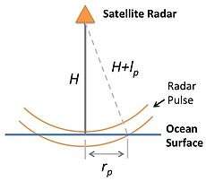

The radar altimeter measures the return power of the radar pulse that's reflected off the land/ocean surface. The temporal evolution of the reflected radar pulse is interpreted in order to estimate the distance between the radar altimeter and the reflecting surface; surface irregularities can also be estimated.[3] The expected return pulse can be derived from a few basic mathematical considerations.[2]
From the previous illustration of the radar pulse vertical cross-section, the radius of the outer edge can be found using the Pythagorean theorem:

where rp is the leading edge of the pulse. If we assume lp2 is small and can be neglected then we can solve for rp as:

The time evolution of the return power measured from the footprint of the radar signal reflecting off the ocean/land surface can be described in three parts: (1) the time before the pulse arrives, (2) the time after the beginning of the pulses arrival and before of the tail of the pulse has arrived, and (3) after the tail of the pulse has arrived. The power function can then be expressed functionally as:
![P(t) = \begin{cases}
0 & t<t_o \\
\pi r^2(t) & t_o<t<t_o+t_p \\
\pi [r^2(t) - r^2(t-t_p)] & t>t_o+t_p \\
\end{cases}](../I/m/afdbfcc34af008222bac621bcb571e37d95a087b.svg)
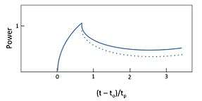
Using the equation for r_p and normalizing by the peak power yields:

This following plot demonstrates the power function for a radar wave pulse. The power function should be constant with time after the full pulse reaches the ocean/land surface (at (t-to)/tp = 1), however the power will actually decrease with time w.r.t the illumination pattern of the radar on the ocean/land surface.[2]

Frequency-modulated continuous-wave radar altimetry
Alternatively, Frequency Modulated Continuous-wave radar can be used. The greater the frequency shift the further the distance traveled. This method can achieve much better accuracy than the pulsed radar for the same outlay and radar altimeters that use frequency modulation are industry standard.
As of 2010, all commercial radar altimeters use linear frequency modulation - continuous wave (LFM-CW or FM-CW). As of 2010, about 25,000 aircraft in the US have at least one radio altimeter. That includes all commercial transport and all business aircraft licensed to fly for hire, which are required to have at least 2 radio altimeters per aircraft.[4][5]
Delay-Doppler (or SAR) Altimetry
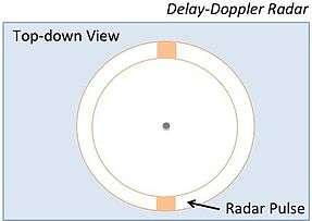
The primary difference between delay-doppler (or Synthetic Aperture Radar) and pulse-limited altimetry is that delay-doppler altimetry looks at a smaller section of the pulse-limited radar footprint, but emits far more pulse signals to give the effect of covering the same footprint as pulse-limited but with better resolution.[6] The top-down view in the figure below shows the decreased footprint size of the delay-doppler signal.
In order to determine the power signal of the delay-doppler radar as a function of time, we'll need to assume that the footprint of the pulsed radar is small enough to be considered two rectangles of width W.[7] This allows the power function to be similarly (see Pulse-limited section above) written as:
![P(t) = \begin{cases}
0 & t<t_o \\
\ 2W r(t) & t_o<t<t_o+t_p \\
\ 2W [r(t) - r(t-t_p)] & t>t_o+t_p \\
\end{cases}](../I/m/bbe73f520f20410dd421a76843cca0862155360a.svg)
Using the equation for the radius derived in the previous section (see Pulse-limited section above), the power vs. time function, normalized by the time relative to the arrival time at the leading edge, , becomes:


An illustration of the normalized power vs. time function is shown below:
There are two primary advantages that the delay-doppler method has over the traditional pulse-limited altimeter. First, the radar footprint is covering less area so it so the radar pulse emitted by the satellite requires much less power.[2] It covers the radar footprint using more frequent, but less power consuming radar pulses. Secondly, the return waveform has a more complex signature allowing the arrival time of the pulse to be more accurately constrained.[2]
Error Budget
The following list notes the error sources associated with radar altimetry measurements:
Tides - Tidal variations are much larger than the dynamic variations in sea surface height.[8] Because tidal periods can be on the order of diurnal and semidiurnal, the tides create an aliased frequency in the temporal variations in the sea level height that must be removed.[8]
Electromagnetic Bias - There is a sea state bias where the troughs of waves tend to focus waves back to the radar, while the crests of the waves scatter waves away from the radar.[9]
Ionosphere - The ionosphere can also impose a delay on the radar return signal, where electron plasma in the ionosphere slow down the group velocity of the radar pulse.[10] The electron density in the ionosphere varies throughout the day, complicating the ionosphere correction.[10]
Dry Troposphere - Refraction from the dry gas component of the atmosphere create a signal delay in the radar, but a correction can be approximated using the Saastamoinen formula:[11] ΔRdry= -0.02277Po*(1+0.0026cos2φ) where Po is the sea level pressure in Pascal and φ the latitude.
Wet Troposphere - Water vapor can also cause a delay in the radar signal which can be more difficult to correct.[12] A delay correction for the total water column in the radar measurement can be accounted for using output from meteorological models, like ECMWF and NCEP.[12]
Invention
In 1924, American engineer Lloyd Espenschied invented the radio altimeter. In 1938, Bell Labs put Espenschied's device in a form that was adaptable for aircraft use.[13] In 1938 in co-operation with Bell Labs, United Air Lines fitted a radar type device to some of its airliners as a terrain avoidance device.[14]
Civil aviation applications
Radar altimeters are frequently used by commercial aircraft for approach and landing, especially in low-visibility conditions (see instrument flight rules) and automatic landings, allowing the autopilot to know when to begin the flare maneuver. Radar altimeters give data to the autothrottle which is a part of the Flight Computer.
Radar altimeters generally only give readings up to 2,500 feet (760 m) above ground level (AGL). Frequently, the weather radar can be directed downwards to give a reading from a longer range, up to 60,000 feet (18,000 m) above ground level (AGL). As of 2012, all airliners are equipped with at least two and possibly more radar altimeters, as they are essential to autoland capabilities. (As of 2012, determining height through other methods such as GPS is not permitted by regulations.) Older airliners from the 1960s (such as the British Aircraft Corporation BAC 1-11) and smaller airliners in the sub-50 seat class (such as the ATR 42 and BAe Jetstream series) are equipped with them.
Radar altimeters are an essential part in ground proximity warning systems (GPWS), warning the pilot if the aircraft is flying too low or descending too quickly. However, radar altimeters cannot see terrain directly ahead of the aircraft, only that below it; such functionality requires either knowledge of position and the terrain at that position or a forward looking terrain radar. Radar altimeter antennas have a fairly large main lobe of about 80° so that at bank angles up to about 40°, the radar detects the range from the aircraft to the ground (specifically to the nearest large reflecting object). This is because range is calculated based on the first signal return from each sampling period. It does not detect slant range until beyond about 40° of bank or pitch. This is not an issue for landing as pitch and roll do not normally exceed 20°.
The altitude specified by the device is not the indicated altitude of the standard barometric altimeter. A radar altimeter measures absolute altitude - the height Above Ground Level (AGL). Absolute altitude is sometimes referred to as height because it is the height above the underlying terrain.
Military aviation applications
Radar altimeters are also used in military aircraft to fly quite low over the land and the sea to avoid radar detection and targeting by anti-aircraft guns or surface-to-air missiles. A related use of radar altimeter technology is terrain-following radar, which allows fighter bombers to fly at very low altitudes.
The F-111s of the Royal Australian Air Force and the U.S. Air Force have a forward-looking, terrain-following radar (TFR) system connected via digital computer to their automatic pilots. Beneath the nose radome are two separate TFR antennae, each providing individual information to the dual-channel TFR system. In case of a failure in that system, the F-111 has a back-up radar altimeter system, also connected to the automatic pilot. Then, if the F-111 ever dips below the preset minimum altitude (for example, 15 meters) for any reason, its automatic pilot is commanded to put the F-111 into a 2G fly-up (a steep nose-up climb) to avoid crashing into terrain or water. Even in combat, the hazard of a collision is far greater than the danger of being detected by an enemy. Similar systems are used by F/A-18 Super Hornet aircraft operated by Australia and the United States.
The radio altimeter first showed up in the German Junkers Ju-87 "Stuka" dive bomber which was equipped with one for automatic pullouts in the dive bomb run which usually consisted of an 80-90 degree dive. The Stuka pilot would set the radio altimeter to 750m which was connected to the bomb release and automatic pull out. The radio altimeter would drop the bombs and pull the Stuka out of the dive at the set altitude to a level flight. This was invented because the pilots would black out on the pull out, usually for 2 to 5 seconds.
See also
References
- ↑ ITU Radio Regulations, Section IV. Radio Stations and Systems – Article 1.108, definition: radio altimeter
- 1 2 3 4 5 Sandwell, David T. "Radar Altimetry" (PDF). Retrieved 1 January 2014.
- ↑ "Radar Altimetry Tutorial: From radar pulse to altimetry measurements". CNES. Retrieved 1 January 2014.
- ↑ "COMMENTS OF AVIATION SPECTRUM RESOURCES, INC.". p. 3, p. 8.
- ↑ Cody Miller. "A Radio Altimeter for Landing UAVs or Small Aircraft". 2010.
- ↑ "Radar Altimetry Tutorial: Delay-Doppler (or SAR) Altimetry". CNES. Retrieved 1 January 2014.
- ↑ Raney, R. K. (1998). "The Delay/Doppler Radar Altimeter". IEEE Trans. Geoscience and Remote Sensing. 36: 1578–1588.
- 1 2 "Radar Altimetry Tutorial: Ocean tides". CNES. Retrieved 1 January 2014.
- ↑ "Radar Altimetry Tutorial: Electromagnetic Bias". CNES. Retrieved 1 January 2014.
- 1 2 "Radar Altimetry Tutorial: Ionospheric corrections". CNES. Retrieved 1 January 2014.
- ↑ "Radar Altimetry Tutorial: Dry troposphere correction". CNES. Retrieved 1 January 2014.
- 1 2 "Radar Altimetry Tutorial: Wet troposphere correction". CNES. Retrieved 1 January 2014.
- ↑ "Radio Altitude: The instrument of choice". Cygnus Interactive.
- ↑ "Towers Flash Radio Beams To Detect Warplanes" Popular Mechanics, September 1941