Bracing (aeronautics)
In aeronautics, bracing comprises additional structural members which stiffen the functional airframe to give it rigidity and strength under load. Bracing may be applied both internally and externally, and may take the form of struts, which act in compression or tension as the need arises, and/or wires, which act only in tension.
In general, bracing allows a stronger, lighter structure than one which is unbraced, but external bracing in particular adds drag which slows down the aircraft and raises considerably more design issues than internal bracing. Another disadvantage of bracing wires is that they require routine checking and adjustment, or rigging, even when located internally.
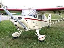
During the early years of aviation, bracing was a universal feature of all forms of aeroplane, including the monoplanes and biplanes which were then equally common. Today, bracing in the form of lift struts is still used for some light commercial designs where a high wing and light weight are more important than ultimate performance.
Design principles
Bracing works by creating a triangulated truss structure which resists bending or twisting. By comparison, an unbraced cantilever structure bends easily unless it carries a lot of heavy reinforcement. Making the structure deeper allows it to be much lighter and stiffer. To reduce weight and air resistance, the structure may be made hollow, with bracing connecting the main parts of the airframe. For example, a high-wing monoplane may be given a diagonal lifting strut running from the bottom of the fuselage to a position far out towards the wingtip. This increases the effective depth of the wing root to the height of the fuselage, making it much stiffer for little increase in weight.
Typically, the ends of bracing struts are joined to the main internal structural components such as a wing spar or a fuselage bulkhead, and bracing wires are attached close by.
Bracing may be used to resist all the various forces which occur in an airframe, including lift, weight, drag and twisting or torsion. A strut is a bracing component stiff enough to resist these forces whether they place it under compression or tension. A wire is a bracing component able only to resist tension, going slack under compression, and consequently is nearly always used in conjunction with struts.
Bracing methods
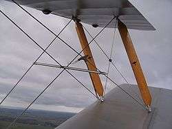
A square frame made of solid bars is not rigid but tends to bend at the corners. Bracing it with an extra diagonal bar would be heavy. A wire would be much lighter but would stop it collapsing only one way. To hold it rigid, two cross-bracing wires are needed. This method of cross-bracing can be seen clearly on early biplanes, where the wings and interplane struts form a rectangle which is cross-braced by wires.
Another way of arranging a rigid structure is to make the cross pieces solid enough to act in compression and then to connect their ends with an outer diamond acting in tension. This method was once common on monoplanes, where the wing and a central cabane or a pylon form the cross members while wire bracing forms the outer diamond.
Bracing wires
Most commonly found on biplane and other multiplane aircraft, wire bracing was also common on early monoplanes.
Unlike struts, bracing wires always act in tension
The thickness and profile of a wire affect the drag it causes, especially at higher speeds. Wires may be made of multi-stranded cable, a single strand of piano wire, or aerofoil sectioned steel.
Bracing wires primarily divide into flying wires which hold the wings down when flying and landing wires which hold the wings up when they are not generating lift. (The wires connecting a basket or gondola to a balloon are also called flying wires.) Thinner incidence wires are sometimes run diagonally between fore and aft interplane struts to stop the wing twisting and changing its angle of incidence to the fuselage.[1] In some pioneer aircraft, wing bracing wires were also run diagonally fore and aft to prevent distortion under side loads such as when turning. Besides the basic loads imposed by lift and gravity, bracing wires must also carry powerful inertial loads generated during manoeuvres, such as the increased load on the landing wires at the moment of touchdown.[2]
Rigging
Bracing wires must be carefully rigged to maintain the correct length and tension. In flight the wires tend to stretch under load and on landing some may become slack. Regular rigging checks are required and any necessary adjustments made before every flight. Rigging adjustments may also be used to set and maintain wing dihedral and angle of incidence, usually with the help of a clinometer and plumb-bob. Individual wires are fitted with turnbuckles or threaded end fittings so that they can be readily adjusted. Once set, the adjuster is locked in place.[3]
Internal bracing
Internal bracing was most significant during the early days of aeronautics when airframes were literally frames, at best covered in doped fabric which had no strength of its own. Wire cross-bracing was extensively used to stiffen such airframes, both in the fabric-covered wings and in the fuselage, which was often left bare.
Routine rigging of the wires was needed to maintain structural stiffness against bending and torsion. A particular problem for internal wires is access in the cramped interior of the fuselage.
External bracing
Often, providing sufficient internal bracing would make a design too heavy, so in order to make the airframe both light and strong the bracing is fitted externally. This was common in early aircraft due to the limited engine power available and the need for light weight in order to fly at all. As engine powers rose steadily through the 1920s and 30s, much heavier airframes became practicable and most designers abandoned external bracing in order to allow for increased speed.
History
Bracing, both internal and external, was extensively used in early aircraft to support the lightweight airframes demanded by the low engine powers and slow flying speeds then available. From the very first Wright flyer of 1903, the fuselage was no more than a braced framework and even fore-aft diagonal bracing was used to hold the wings at right angles to it.
Some very early aircraft used struts made from bamboo. Most designs employed streamlined struts made either from spruce or ash wood, selected for its strength and light weight.[2] Metal struts were also used, and both wood and metal continue in use today.
The need for fore-aft wing bracing disappeared with the advent of more powerful engines in 1909, but bracing remained essential for any practical design, even on monoplanes up until World War I when they became unpopular and braced biplanes reigned supreme.
From 1911, the British researcher Harris Booth working at the National Physics Laboratory and the engineer Richard Fairey, then working for J.W. Dunne's Blair Atholl Aeroplane Syndicate, began to develop and apply the engineering analysis of individual bays in a biplane, to calculate the structural forces and use the minimal amount of material in each bay to achieve maximum strength.[4] Analytical techniques such as this led to lighter and stronger aircraft and became widely adopted.
At the same time, the amount of bracing could be progressively reduced. At low speeds a thin wire causes very little drag and early flying machines were sometimes called "bird cages" due to the number of wires present. However, as speeds rise the wire must be made thinner to avoid drag while the forces it carries increase. The steady increase in engine power allowed an equally steady increase in weight, necessitating less bracing. Special bracing wires with flat or aerofoil sections were also developed in attempts to further reduce drag.
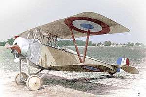
By the end of World War I engine powers and airspeeds had risen enough that the drag caused by bracing wires on a typical biplane was significantly affecting performance, while the heavier but sleeker strut-braced parasol monoplane was becoming practicable. For a brief period this type of monoplane became the design of choice. Although it was soon outpaced by the true cantilever monoplane, it has remained in use ever since where ultimate performance is not an issue.
Boeing's proposed SUGAR Volt includes a braced, high aspect ratio wing for low drag and high lift.
Biplanes

Nearly all biplane aircraft have their upper and lower planes connected by interplane struts, with the upper wing running across above the fuselage and connected to it by shorter cabane struts. These struts divide the wings into bays which are braced by diagonal wires. The flying wires run upwards and outwards from the lower wing, while the landing wires run downwards and outwards from the upper wing. The resulting combination of struts and wires is a rigid box girder-like structure independent of its fuselage mountings.
Interplane struts
interplane struts hold apart the wings of a biplane or multiplane, also helping to maintain the correct angle of incidence for the connected wing panels.
Parallel struts: The most common configuration is for two struts to be placed in parallel, one behind the other. These struts will usually be braced by "incidence wires" running diagonally between them. These wires resist twisting of the wing which would affect its angle of incidence to the airflow.
N-struts replace the incidence wires by a third strut running diagonally from the top of one strut to the bottom of the other in a pair.
V-struts converge from separate attachment points on upper wing to a single point on the lower wing. They are often used for the sesquiplane wing, in which the lower wing has a considerably smaller chord than the upper wing.
I-struts replaces the usual pair of struts by a single, thicker streamlined strut with its ends extended fore and aft along the wing.
Bays
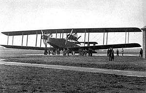
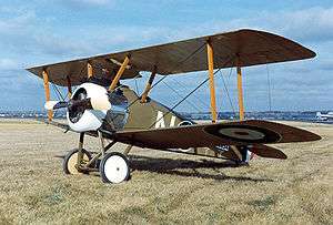
The span of a wing between two sets of interplane or cabane struts is called a bay. Wings are described by the number of bays on each side. For example, a biplane with cabane struts and one set of interplane struts on each side of the aircraft is a single-bay biplane.
For a small type such as a World War I scout like the Fokker D.VII, one bay is usually enough. But for larger wings carrying greater payloads, several bays may be used. The two-seat Curtiss JN-4 Jenny is a two-bay biplane, while large heavy types were often multi-bay biplanes or triplanes — the German DFW B.I was one of the very few single-engined, three-bay biplanes used during World War I .
Some biplane wings are braced with struts leaned sideways with the bays forming a zigzag Warren truss. Examples include the Fiat CR.42 Falco.
Other variations have also been used. The SPAD S.XIII fighter, while appearing to be a two bay biplane, has only one bay, but has the midpoints of the rigging braced with additional struts, however these are not structurally contiguous from top to bottom wing. The Sopwith 1½ Strutter has a W shape cabane, however as it doesn't connect the wings to each other, it doesn't add to the number of bays.
Interplane strut gallery
-
Parallel struts on a Sopwith Camel
-
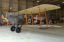
V-struts on a Nieuport 10
-

N-struts on a Boeing-Stearman Model 75
-
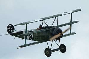
I-struts on a Fokker Dr.1 triplane
-
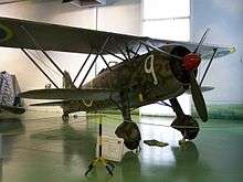
Warren truss struts on a Fiat C.R.42
Cabane struts
Where an aircraft has a wing running clear above the main fuselage, the two components are often connected by cabane struts running up from the top of the fuselage or crew cabin to the wing centre section. Such a wing is usually also braced elsewhere, with the cabane struts forming part of the overall bracing scheme.
Because cabane struts often carry engine thrust to the upper wing to overcome its drag, the loads along each diagonal between fore and aft struts are unequal and they are often formed as N-struts. They may also have cross-braced torsion wires to help stop the wing twisting. A few biplane designs, like the British 1917 Bristol Fighter two-seat fighter/escort, had its fuselage clear of the lower wing as well as the upper one, using ventral cabane struts to accomplish such a design feature.
Monoplanes

Early monoplanes relied entirely on external wire bracing, either directly to the fuselage or to kingposts above it and undercarriage struts below to resist the same forces of lift and gravity. Many later monoplanes have used cantilever wings with their lift bracing within the wing to avoid the drag penalties of external wires and struts,
Cabanes
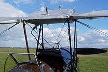
In many early wire-braced monoplanes, e.g. the Blériot XI, a rigid cage or cabane was raised above the fuselage. This could be used both to provide some protection to the pilot if the craft overturned on the ground, and also for the attachment of landing wires which ran out in a slightly inclined vee to fore and aft points near the wing tips. In parasol wing monoplanes the wing passes above the fuselage and is joined to the fuselage by cabane struts, similarly to the upper wing of a biplane.[5]
On some types the cabane is replaced by a single thick, streamlined pylon.
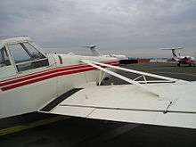
Lift struts
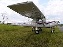
On a high-wing aircraft, a lift strut connects an outboard point on the wing with a point lower on the fuselage to form a rigid triangular structure. While in flight the strut acts in tension to carry wing lift to the fuselage and hold the wing level, while when back on the ground it acts in compression to hold the wing up.[6]
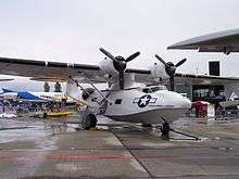
For aircraft of moderate engine power and speed, lift struts represent a compromise between the high drag of a fully cross-braced structure and the high weight of a fully cantilevered wing. They are common on high-wing types such as the Cessna 152 and almost universal on parasol-winged types such as the Consolidated PBY Catalina.
Less commonly, some low-winged monoplanes like the Piper Pawnee have had lift struts mounted above the wing, acting in compression in flight and in tension on the ground.
Sometimes each wing has just a single lift strut, as on the Cessna 152, but they often come in pairs, sometimes parallel as on the Catalina, sometimes splayed or as V-form pairs (e.g. Auster Autocrat) joined to the fuselage at a single point. Many more complicated arrangements have been used, often with two primary lift struts augmented by auxiliary interconnections known as jury struts between each other or to the wing or the fuselage. Each pair of the inverted V struts of the Pawnee, for example, is assisted by a pair of vertical support struts.[7]
From early times these lift struts have been streamlined, often by enclosing metal load bearing members in shaped casings. The Farman F.190, for example, had its high wings joined to the lower fuselage by parallel duralumin tubes enclosed in streamlined spruce fairings[8] and the Westland Lysander used extruded I section beams of light alloy, onto which were screwed a fore and aft pair of duralumin fairings.[9] Later aircraft have had streamlined struts formed directly from shaped metal, like the extruded light alloy struts of the Auster AOP.9,[10] or from composites, for example the carbon fibre lift struts of the Remos GX eLITE.[11] Designers have adopted different methods of improving the aerodynamics of the strut-wing and strut-body, using similar approaches to those used in interplane struts. Sometimes the streamlining is tapered away close to the wing, as on the Farman F.190;[8] other designs have an extended, faired foot, for example the Skyeton K-10 Swift.[12]
Lift struts are sometimes combined with other functions, for example helping to support the engines as on the Westland IV or the undercarriage as on the Scottish Aviation Twin Pioneer.[13][14]
Lift struts remain common on small (2/4-seat) high-wing light aircraft in the ultralight and light-sport categories. Larger examples include the Pilatus Porter 10-seat STOL passenger aircraft and the de Havilland Twin Otter 19-seater.[15][16][17][18]
Jury struts
A lift strut can be so long and thin that it bends too easily. Jury struts are small subsidiary struts used to stiffen it.[19]
Problems which jury struts prevent include resonant vibration and buckling under compressive loads.
Jury struts come in many configurations. On monoplanes with one main strut, there may be just a single jury strut connecting the main strut to an intermediate point on the wing. A braced monoplane with 'V' struts such as the Fleet Canuck may have a complicated assembly of jury struts.
See also
References
Notes
- ↑ de Havilland Aircraft Company. The de Havilland DH82A Tiger Moth - Maintenance and Repair Manual, Third Edition . Hatfield, Hertfordshire. The de Havilland Aircraft Company Ltd. (Date unknown)
- 1 2 Taylor, 1990. p.71.
- ↑ Halliwell 1919, p.107.
- ↑ Ledeboer, J.H.; Aeronautics, Vol. 18, 1920, page 81.
- ↑ Crane 1997, Page 379
- ↑ Kumar, Bharat (2005). An Illustrated Dictionary of Aviation. New York: McGraw Hill. ISBN 0-07-139606-3.
- ↑ Taylor, John W R (1966). Jane's All the World's Aircraft 1966-67. London: Sampson Low, Marston & Co. Ltd. p. 309.
- 1 2 Barrière, Michael. "The Farman 190 and its derivatives". Air-Britain Archive (December 2010): 187.
- ↑ James, Derek (1991). Westland Aircraft since 1915. London: Putnam Publishing. p. 236. ISBN 0-85177-847-X.
- ↑ Bridgman, Leonard (1956). Jane's All the World's Aircraft 1956-57. London: Jane's All the World's Aircraft Publishing Co. Ltd. p. 47.
- ↑ "New Remos GX eLITE". 13 April 2011. Retrieved 2011-04-15.
- ↑ Jackson, Paul (2010). Jane's All the World's Aircraft 2010-11. Coulsdon, Surrey: IHS Jane's. pp. 613–4. ISBN 978-0-7106-2916-6.
- ↑ Jackson, A.J. (1960). British Civil Aircraft 1919-59. 2. London: Putnam Publishing. p. 327.
- ↑ Jackson, A.J. (1960). British Civil Aircraft 1919-59. 2. London: Putnam Publishing. p. 227.
- ↑ Simpson, Rod (2001). Airlife's World Aircraft. Shrewsbury: Airlife Publishing Ltd. p. 427. ISBN 1-84037-115-3.
- ↑ "Pilatus PC-6". Retrieved 2011-04-14.
- ↑ "de Havilland Twin Otter Series 400". Retrieved 2011-04-15.
- ↑ Simpson, Rod (2001). Airlife's World Aircraft. Shrewsbury: Airlife Publishing Ltd. p. 186. ISBN 1-84037-115-3.
- ↑ Crane 1997, Page 294.
Bibliography
- Crane, Dale: Dictionary of Aeronautical Terms, third edition, Aviation Supplies & Academics, 1997. ISBN 1-56027-287-2
- Halliwell, F.W. "Rigging: The Erection and Trueing-Up of Aeroplanes". Flight, 23 January 1919. p. 107.
- Kumar, B. An Illustrated Dictionary of Aviation. New York McGraw Hill, 2005. ISBN 0-07-139606-3
- Steventon, H.W.B.; "Theoretical Considerations in the Design of Wing Strut Joints", The Aircraft Engineer: Supplement to Flight, 30 May 1930, Pages 33–35 (Flight Pages 586a-586c).
- Taylor, John W.R. The Lore of Flight, London: Universal Books Ltd., 1990. ISBN 0-9509620-1-5.