Adhesion railway
Adhesion railway or adhesion traction is the most common type of railway, where power is applied by driving some or all of the wheels of the locomotive.[1] Rail adhesion relies on the friction between a steel wheel and a steel rail. The term is particularly used when discussing conventional railways to distinguish from other forms of traction such as funicular or cog railway.
Traction or friction can be reduced when the rails are greasy, because of rain, oil or decomposing leaves which compact into a hard slippery lignin coating. Measures against reduced adhesion due to leaves include application of "Sandite" (a gel-sand mix) by special sanding trains, scrubbers and water jets, and long-term management of railside vegetation. On an adhesion railway, most locomotives will have a sand containment vessel, to apply sand onto the track; this is called "sanding".
Effect of adhesion limits
Adhesion is caused by friction, with maximum tangential force produced by a driving wheel before slipping given by:
- Fmax= coefficient of friction × Weight on wheel[2]
Usually the force needed to start sliding is greater than that needed to continue sliding. The former is concerned with static friction, referred colloquially to as "stiction", or "limiting friction", whilst the latter is dynamic friction, also called "sliding friction".
For steel on steel, the coefficient of friction can be as high as 0.78, under laboratory conditions, but typically on railways it is between 0.35 and 0.5,[3] whilst under extreme conditions it can fall to as low as 0.05. Thus a 100-tonne locomotive could have a tractive effort of 350 kilonewtons, under the ideal conditions (assuming sufficient force can be produced by the engine), falling to a 50 kilonewtons under the worst conditions.
Steam locomotives suffer particularly badly from adhesion issues because power delivery is pulsed (especially in 2- or most 4-cylinder engines) and, on large locomotives, not all wheels are driven. The "factor of adhesion", being the weight on the driven wheels divided by the theoretical starting tractive effort, was generally designed to be a value of 4 or higher, reflecting a typical wheel-rail friction coefficient of 0.25. A locomotive with a factor of adhesion much lower than 4 would be highly prone to wheelslip. Other steam locomotive design factors significantly affecting traction include wheel size (smaller diameter wheels offer superior traction at the expense of top speed) and the sensitivity of the regulator.
All-weather adhesion
The term all-weather adhesion is usually used in North America, and refers to the adhesion available during traction mode with 99% reliability in all weather conditions.[4]
Toppling conditions
The maximum speed a train can proceed around a turn is limited by the radius of turn, the position of the centre of mass of the units, the wheel gauge and whether the track is superelevated or canted (see cant (road/rail)).

Toppling will occur when the overturning moment due to the side force (centrifugal acceleration) is sufficient to cause the inner wheel to begin to lift off the rail. This may result in loss of adhesion - causing the train to slow, preventing toppling. Alternatively, the inertia may be sufficient to cause the train to continue to move at speed causing the vehicle to topple completely.
For a wheel gauge of 1.5 m, no canting, a centre of gravity height of 3 m and speed of 30 m/s (108 km/h), the radius of turn is 360 m. For a modern high speed train at 80 m/s, the toppling limit would be about 2.5 km. In practice, the minimum radius of turn is much greater than this, as contact between the wheel flanges and rail at high speed could cause significant damage to both. For very high speed, the minimum adhesion limit again appears appropriate, implying a radius of turn of about 13 km. In practice, curved lines used for high speed travel are superelevated or canted so that the turn limit is closer to 7 km.
During the 19th century, it was widely believed that coupling the drive wheels would compromise performance and was avoided on engines intended for express passenger service. With a single drive wheelset, the Herzian contact stress between the wheel and rail necessitated the largest diameter wheels that could be accommodated. The weight of locomotive was restricted by the stress on the rail and sandboxes were required, even under reasonable adhesion conditions.
Directional stability and hunting instability
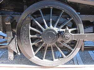
It may be thought that the wheels are kept on the tracks by the flanges. However, close examination of a typical railway wheel reveals that the tread is burnished but the flange is not - the flanges rarely make contact with the rail and, when they do, most of the contact is sliding. The rubbing of a flange on the track dissipates large amounts of energy, mainly as heat but also including noise and, if sustained, would lead to excessive wheel wear.
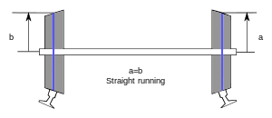
Centring is actually accomplished through shaping of the wheel. The tread of the wheel is slightly tapered. When the train is in the centre of the track, the region of the wheels in contact with the rail traces out a circle which has the same diameter for both wheels. The velocities of the two wheels are equal, so the train moves in a straight line.
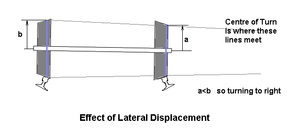
If, however, the wheelset is displaced to one side, the diameters of the regions of contact, and hence the tangential velocities of the wheels at the running surfaces are different and the wheelset tends to steer back towards the centre. Also, when the train encounters an unbanked turn, the wheelset displaces laterally slightly, so that the outer wheel tread speeds up linearly, and the inner wheel tread slows down, causing the train to turn the corner. Some railway systems employ a flat wheel and track profile, relying on cant alone to reduce or eliminate flange contact.
Understanding how the train stays on the track, it becomes evident why Victorian locomotive engineers were averse to coupling wheelsets. This simple coning action is possible only with wheelsets where each can have some free motion about its vertical axis. If wheelsets are rigidly coupled together, this motion is restricted, so that coupling the wheels would be expected to introduce sliding, resulting in increased rolling losses. This problem was alleviated to a great extent by ensuring the diameter of all coupled wheels was very closely matched.
With perfect rolling contact between the wheel and rail, this coning behaviour manifests itself as a swaying of the train from side to side. In practice, the swaying is damped out below a critical speed, but is amplified by the forward motion of the train above the critical speed. This lateral swaying is known as hunting oscillation. The phenomenon of hunting was known by the end of the 19th century, although the cause was not fully understood until the 1920s and measures to eliminate it were not taken until the late 1960s. The limitation on maximum speed was imposed not by raw power but by encountering an instability in the motion.
The kinematic description of the motion of tapered treads on the two rails is insufficient to describe hunting well enough to predict the critical speed. It is necessary to deal with the forces involved. There are two phenomena which must be taken into account. The first is the inertia of the wheelsets and vehicle bodies, giving rise to forces proportional to acceleration; the second is the distortion of the wheel and track at the point of contact, giving rise to elastic forces. The kinematic approximation corresponds to the case which is dominated by contact forces.
A fairly straightforward analysis of the kinematics of the coning action yields an estimate of the wavelength of the lateral oscillation:

where d is the wheel gauge, r is the nominal wheel radius and k is the taper of the treads. For a given speed, the longer the wavelength and the lower the inertial forces will be, so the more likely it is that the oscillation will be damped out. Since the wavelength increases with reducing taper, increasing the critical speed requires the taper to be reduced, which implies a large minimum radius of turn.
A more complete analysis, taking account of the actual forces acting, yields the following result for the critical speed of a wheelset:

where W is the axle load for the wheelset, a is a shape factor related to the amount of wear on the wheel and rail, C is the moment of inertia of the wheelset perpendicular to the axle, m is the wheelset mass.
The result is consistent with the kinematic result in that the critical speed depends inversely on the taper. It also implies that the weight of the rotating mass should be minimised compared with the weight of the vehicle. The wheel gauge implicitly appears in both the numerator and denominator, implying that it has only a second-order effect on the critical speed.
The true situation is much more complicated, as the response of the vehicle suspension must be taken into account. Restraining springs, opposing the yaw motion of the wheelset, and similar restraints on bogies, may be used to raise the critical speed further. However, in order to achieve the highest speeds without encountering instability, a significant reduction in wheel taper is necessary, so there is little prospect of reducing the turn radius of high speed trains much below the current value of 7 km.
Forces on wheels, creep
The behaviour of adhesion railways is determined by the forces arising between two surfaces in contact. This may appear trivially simple from a superficial glance but it becomes extremely complex when studied to the depth necessary to predict useful results.
The first error to address is the assumption that wheels are round. A glance at the tyres of a parked car will immediately show that this is not true: the region in contact with the road is noticeably flattened, so that the wheel and road conform to each other over a region of contact. If this were not the case, the contact stress of a load being transferred through a point contact would be infinite. Rails and railway wheels are much stiffer than pneumatic tyres and tarmac but the same distortion takes place at the region of contact. Typically, the area of contact is elliptical, of the order of 15 mm across.[5]


The distortion is small and localised but the forces which arise from it are large. In addition to the distortion due to the weight, both wheel and rail distort when braking and accelerating forces are applied and when the vehicle is subjected to side forces. These tangential forces cause distortion in the region where they first come into contact, followed by a region of slippage. The net result is that, during traction, the wheel does not advance as far as would be expected from rolling contact but, during braking, it advances further. This mix of elastic distortion and local slipping is known as "creep" (not to be confused with the creep of materials under constant load). The definition of creep[6] in this context is:

In analysing the dynamics of wheelsets and complete rail vehicles, the contact forces can be treated as linearly dependent on the creep [7](Kalker's linear theory, valid for small creepage) or more advanced theories can be used from frictional contact mechanics.
The forces which result in directional stability, propulsion and braking may all be traced to creep. It is present in a single wheelset and will accommodate the slight kinematic incompatibility introduced by coupling wheelsets together, without causing gross slippage, as was once feared.
Provided the radius of turn is sufficiently great (as should be expected for express passenger services), two or three linked wheelsets should not present a problem. However, 10 drive wheels (5 main wheelsets) are usually associated with heavy freight locomotives.
Sanding
On an adhesion railway, most locomotives will have a sand containment vessel. Properly dried sand can be dropped onto the rail to improve traction under slippery conditions. The sand is most often applied using compressed air via tower, crane, silo or train.[8][9] When an engine slips, particularly when starting a heavy train, sand applied at the front of the driving wheels greatly aids in tractive effort causing the train to "lift", or to commence the motion intended by the engine driver.
Sanding however also has some negative effects. It can cause a "sandfilm", which consists of crushed sand, that is compressed to a film on the track where the wheels make contact. Together with some moisture on the track, which acts as a light adhesive and keeps the applied sand on the track, the wheels "bake" the crushed sand into a more solid layer of sand. Because the sand is applied to the first wheels on the locomotive, the following wheels may run, at least partially and for a limited time, on a layer of sand (sandfilm). While traveling this means that electric locomotives may lose contact to the track-ground, causing the locomotive to create EMI-emissions and currents through the couplers, or in standstill, when the locomotive is parked, "track-release-relays" may detect an empty track because the locomotive is electrically isolated from the track.[10]
Booster
Some steam locomotives were fitted with booster engines on the rear trailing wheels. These were turned on as required at starting to give additional adhesive effort.
See also
Footnotes
- ↑ "Combined Adhesion ad Cog-Wheel Railways". The Railway News and Joint Stock Journal. London. 51 (1307): 100–101. January 19, 1889.
- ↑ Engineering Mechanics. PHI Learning Pvt. Ltd. 2013-01-01. ISBN 9788120342941.
- ↑ École Polytechnique Fédérale de Lausanne. (PDF) http://documents.epfl.ch/users/a/al/allenbac/www/documents/ResuTE31.pdf. Missing or empty
|title=(help) - ↑ "EPR 012: Testing of locomotive all weather adhesion" (PDF). RailCorp. October 2011. Retrieved October 25, 2014.
- ↑ "Science of Railway Locomotion". www.brooklynrail.net. Retrieved 2016-02-04.
- ↑ Wikins (2003), p. 6, Section 1.3 Creep (see Fig. 1.5a)
- ↑ See *Деев В.В., Ильин Г.А., Афонин Г.С. (Russian) "Тяга поездов" (Traction of trains) Учебное пособие. - М.: Транспорт, 1987. - Fig. 2.3 p.30 for a curve (which is linear at first) relating creep to tangential force
- ↑ "Locomotive Sanding Systems & Rail Traction | Cyclonaire". Cyclonaire. Retrieved 2016-02-04.
- ↑ "The Adhesion Rail Riddle - Ensuring Trains Can Brake | Engineering and the Environment | University of Southampton". www.southampton.ac.uk. Retrieved 2016-02-04.
- ↑ Bernd Sengespeick (2013-08-08). "Hybrid vehicle air conditioning service" (PDF). EBA. Retrieved 2013-08-08.[source needs translation]
References
- Carter, F W (July 25, 1928). On the Stability of Running of Locomotives. Proc. Royal Society.
- Inglis, Sir Charles (1951). Applied Mathematics for Engineers. Cambridge University Press. pp. 194–195.
- Wickens, A H (1965–1966). "The Dynamics of Railway Vehicles on Straight Track: Fundamental Considerations of Lateral Stability". Proc. Inst. Mech. Eng.: 29.
- Wickens, A H; Gilchrist, A O; Hobbs, A E W (1969–1970). Suspension Design for High-Performance Two-Axle Freight Vehicles. Proc. Inst. Mech. Eng. p. 22. by A H Wickens
- Wikins, A H (Jan 1, 2003). Fundamentals of rail vehicle dynamics : guidance and stability. Swets & Zeitlinger.