Solar inverter
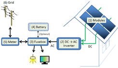
A solar inverter, or converter or PV inverter, converts the variable direct current (DC) output of a photovoltaic (PV) solar panel into a utility frequency alternating current (AC) that can be fed into a commercial electrical grid or used by a local, off-grid electrical network. It is a critical balance of system (BOS)–component in a photovoltaic system, allowing the use of ordinary AC-powered equipment. Solar power inverters have special functions adapted for use with photovoltaic arrays, including maximum power point tracking and anti-islanding protection.
Classification
Solar inverters may be classified into three broad types:
- Stand-alone inverters, used in isolated systems where the inverter draws its DC energy from batteries charged by photovoltaic arrays. Many stand-alone inverters also incorporate integral battery chargers to replenish the battery from an AC source, when available. Normally these do not interface in any way with the utility grid, and as such, are not required to have anti-islanding protection.
- Grid-tie inverters, which match phase with a utility-supplied sine wave. Grid-tie inverters are designed to shut down automatically upon loss of utility supply, for safety reasons. They do not provide backup power during utility outages.
- Battery backup inverters, are special inverters which are designed to draw energy from a battery, manage the battery charge via an onboard charger, and export excess energy to the utility grid. These inverters are capable of supplying AC energy to selected loads during a utility outage, and are required to have anti-islanding protection.
Maximum power point tracking
Solar inverters use maximum power point tracking (MPPT) to get the maximum possible power from the PV array.[2] Solar cells have a complex relationship between solar irradiation, temperature and total resistance that produces a non-linear output efficiency known as the I-V curve. It is the purpose of the MPPT system to sample the output of the cells and determine a resistance (load) to obtain maximum power for any given environmental conditions.[3]
The fill factor, more commonly known by its abbreviation FF, is a parameter which, in conjunction with the open circuit voltage (Voc) and short circuit current (Isc) of the panel, determines the maximum power from a solar cell. Fill factor is defined as the ratio of the maximum power from the solar cell to the product of Voc and Isc.[4]
There are three main types of MPPT algorithms: perturb-and-observe, incremental conductance and constant voltage.[5] The first two methods are often referred to as hill climbing methods; they rely on the curve of power plotted against voltage rising to the left of the maximum power point, and falling on the right.[6]
Solar micro-inverters

Solar micro-inverter is an inverter designed to operate with a single PV module. The micro-inverter converts the direct current output from each panel into alternating current. Its design allows parallel connection of multiple, independent units in a modular way.[7]
Micro-inverter advantages include single panel power optimization, independent operation of each panel, plug-and play installation, improved installation and fire safety, minimized costs with system design and stock minimization.
A 2011 study at Appalachian State University reports that individual integrated inverter setup yielded about 20% more power in unshaded conditions and 27% more power in shaded conditions compared to string connected setup using one inverter. Both setups used identical solar panels.[8]
Grid tied solar inverters
Solar grid-tie inverters are designed to quickly disconnect from the grid if the utility grid goes down. This is an NEC requirement that ensures that in the event of a blackout, the grid tie inverter will shut down to prevent the energy it produces from harming any line workers who are sent to fix the power grid.
Grid-tie inverters that are available on the market today use a number of different technologies. The inverters may use the newer high-frequency transformers, conventional low-frequency transformers, or no transformer. Instead of converting direct current directly to 120 or 240 volts AC, high-frequency transformers employ a computerized multi-step process that involves converting the power to high-frequency AC and then back to DC and then to the final AC output voltage.[9]
Historically, there have been concerns about having transformerless electrical systems feed into the public utility grid. The concerns stem from the fact that there is a lack of galvanic isolation between the DC and AC circuits, which could allow the passage of dangerous DC faults to the AC side.[10] Since 2005, the NFPA's NEC allows transformerless (or non-galvanically) inverters. The VDE 0126-1-1 and IEC 6210 also have been amended to allow and define the safety mechanisms needed for such systems. Primarily, residual or ground current detection is used to detect possible fault conditions. Also isolation tests are performed to insure DC to AC separation.
Many solar inverters are designed to be connected to a utility grid, and will not operate when they do not detect the presence of the grid. They contain special circuitry to precisely match the voltage, frequency and phase of the grid.
Solar charge controller
A charge controller may be used to power DC equipment with solar panels. The charge controller provides a regulated DC output and stores excess energy in a battery as well as monitoring the battery voltage to prevent under/over charging. More expensive units will also perform maximum power point tracking. An inverter can be connected to the output of a charge controller to drive AC loads.
Solar pumping inverters
Advanced solar pumping inverters convert DC voltage from the solar array into AC voltage to drive submersible pumps directly without the need for batteries or other energy storage devices. By utilizing MPPT (maximum power point tracking), solar pumping inverters regulate output frequency to control the speed of the pumps in order to save the pump motor from damage.
Solar pumping inverters usually have multiple ports to allow the input of DC current generated by PV arrays, one port to allow the output of AC voltage, and a further port for input from a water-level sensor.
Market
As of 2014, conversion efficiency for state-of-the-art solar converters reached more than 98 percent. While string inverters are used in residential to medium-sized commercial PV systems, central inverters cover the large commercial and utility-scale market. Market-share for central and string inverters are about 50 percent and 48 percent, respectively, leaving less than 2 percent to micro-inverters.[11]
| Type | Power | Efficiency(a) | Market share(b) |
Remarks |
|---|---|---|---|---|
| String inverter | up to 100 kWp(c) | 98% | 50% | Cost(b) €0.15 per watt-peak. Easy to replace. |
| Central inverter | above 100 kWp | 98.5% | 48% | €0.10 per watt-peak. High reliability. Often sold along with a service contract. |
| Micro-inverter | module power range | 90%–95% | 1.5% | €0.40 per watt-peak. Ease of replacement concerns. |
| DC/DC converter Power optimizer |
module power range | 98.8% | N/A | €0.40 per watt-peak. Ease of replacement concerns. Inverter is still needed. About 0.75 GWP installed in 2013. |
| Source: data by IHS 2014, remarks by Fraunhofer ISE 2014, from: Photovoltaics Report, updated as per 8 September 2014, p. 35, PDF[11] Notes: (a)best efficiencies displayed, (b)market-share and cost per watt are estimated, (c)kWp = kilowatt-peak | ||||
See also
References
- ↑ Solar Cells and their Applications Second Edition, Lewis Fraas, Larry Partain, Wiley, 2010, ISBN 978-0-470-44633-1 , Section10.2.
- ↑ "Invert your thinking: Squeezing more power out of your solar panels". scientificamerican.com. Retrieved 2011-06-09.
- ↑ Comparison of Photovoltaic Array Maximum Power Point Tracking Techniques
- ↑ Benanti, Travis L.; Venkataraman, D. (25 April 2005). "Organic Solar Cells: An Overview Focusing on Active Layer Morphology" (PDF). Photosynthesis Research. 87 (1): 77. doi:10.1007/s11120-005-6397-9. Retrieved 27 August 2013.
- ↑ "Evaluation of Micro Controller Based Maximum Power Point Tracking Methods Using dSPACE Platform" (PDF). itee.uq.edu.au. Retrieved 2011-06-14.
- ↑ "Comparative Study of Maximum Power Point Tracking Algorithms". doi:10.1002/pip.459.
- ↑ http://dspace.mit.edu/bitstream/handle/1721.1/61308/702674669.pdf
- ↑ "A SIDE-BY-SIDE COMPARISON OF MICRO AND CENTRAL INVERTERS IN SHADED AND UNSHADED CONDITIONS" (PDF). Retrieved 27 August 2013.
- ↑ Photovoltaics: Design and Installation Manual. Newsociety Publishers. 2004. p. 80.
- ↑ "Summary Report on the DOE High-tech Inverter Workshop" (PDF). Sponsored by the US Department of Energy, prepared by McNeil Technologies. eere.energy.gov. Retrieved 2011-06-10.
- 1 2 Fraunhofer ISE report , archived version as per September 2014 (archived PDF)