Stress concentration

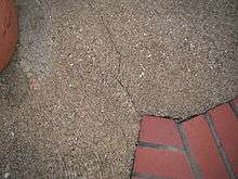
A stress concentration (often called stress raisers or stress risers) is a location in an object where stress is concentrated. An object is strongest when force is evenly distributed over its area, so a reduction in area, e.g., caused by a crack, results in a localized increase in stress. A material can fail, via a propagating crack, when a concentrated stress exceeds the material's theoretical cohesive strength. The real fracture strength of a material is always lower than the theoretical value because most materials contain small cracks or contaminants (especially foreign particles) that concentrate stress. Fatigue cracks always start at stress raisers, so removing such defects increases the fatigue strength.
Causes

Geometric discontinuities cause an object to experience a local increase in the intensity of a stress field. Examples of shapes that cause these concentrations are cracks, sharp corners, holes, and changes in the cross-sectional area of the object. High local stresses can cause objects to fail more quickly, so engineers must design the geometry to minimize stress concentrations.
Prevention
A counter-intuitive method of reducing one of the worst types of stress concentrations, a crack, is to drill a large hole at the end of the crack. The drilled hole, with its relatively large diameter, causes a smaller stress concentration than the sharp end of a crack. This is however, a temporary solution that must be corrected at the first opportune time.
It is important to systematically check for possible stress concentrations caused by cracks—there is a critical crack length of 2a for which, when this value is exceeded, the crack proceeds to definite catastrophic failure. This ultimate failure is definite since the crack will propagate on its own once the length is greater than 2a. (There is no additional energy required to increase the crack length so the crack will continue to enlarge until the material fails.) The origins of the value 2a can be understood through Griffith's theory of brittle fracture.
Another method used to decrease the stress concentration is by creating the fillet at the sharp edges. It gives smooth flow of stress streamlines. In a threaded component force flow line is bent as it passes from shank portion to threaded portion as a result stress concentration takes place. To reduce this a small undercut is taken between shank and threaded portion.
Examples
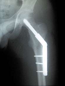
The term "stress raiser" is used in orthopedics; a focus point of stress on an implanted orthosis is very likely to be its point of failure.
Classic cases of metal failures due to stress concentrations include metal fatigue at the corners of the windows of the De Havilland Comet aircraft and brittle fractures at the corners of hatches in Liberty ships in cold and stressful conditions in winter storms in the Atlantic Ocean.
Concentration factor for cracks
The maximum stress felt near a crack occurs in the area of lowest radius of curvature. In an elliptical crack of length and width , under an applied external stress , the stress at the ends of the major axes is given by Inglis' equation:
where ρ is the radius of curvature of the crack tip. A stress concentration factor is the ratio of the highest stress () to a reference stress () of the gross cross-section. As the radius of curvature approaches zero, the maximum stress approaches infinity. Note that the stress concentration factor is a function of the geometry of a crack, and not of its size. These factors can be found in typical engineering reference materials to predict the stresses that could otherwise not be analyzed using strength of materials approaches. This is not to be confused with 'Stress Intensity Factor'.[1]
Concentration factor calculation
There are experimental methods for measuring stress concentration factors including photoelastic stress analysis, brittle coatings or strain gauges. While all these approaches have been successful, all also have experimental, environmental, accuracy and/or measurement disadvantages.
During the design phase, there are multiple approaches to estimating stress concentration factors. Several catalogs of stress concentration factors have been published. Perhaps most famous is Stress Concentration Design Factors by Peterson, first published in 1953.[2] Finite element methods are commonly used in design today. Theoretical approaches, using elasticity or strength of material considerations, can lead to equations similar to the one shown above.
There may be small differences between the catalog, FEM and theoretical values calculated. Each method has advantages and disadvantages. Many catalog curves were derived from experimental data. FEM calculates the peak stresses directly and nominal stresses may be easily found by integrating stresses in the surrounding material. The result is that engineering judgment may have to be used when selecting which data applies to making a design decision. Many theoretical stress concentration factors have been derived for infinite or semi-infinite geometries which may not be analyzable and are not testable in a stress lab, but tackling a problem using two or more of these approaches will allow an engineer to achieve an accurate conclusion.
See also
References
- ESDU64001: Guide to stress concentration data (ISBN 1-86246-279-8)
- Pilkey, Walter D, Peterson's Stress Concentration Factors, Wiley, 2nd Ed (1999). ISBN 0-471-53849-3
