Fatigue (material)
In materials science, fatigue is the weakening of a material caused by repeatedly applied loads. It is the progressive and localised structural damage that occurs when a material is subjected to cyclic loading. The nominal maximum stress values that cause such damage may be much less than the strength of the material typically quoted as the ultimate tensile stress limit, or the yield stress limit.
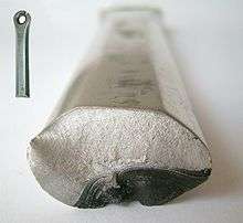
Fatigue occurs when a material is subjected to repeated loading and unloading. If the loads are above a certain threshold, microscopic cracks will begin to form at the stress concentrators such as the surface, persistent slip bands (PSBs), and grain interfaces.[1] Eventually a crack will reach a critical size, the crack will propagate suddenly, and the structure will fracture. The shape of the structure will significantly affect the fatigue life; square holes or sharp corners will lead to elevated local stresses where fatigue cracks can initiate. Round holes and smooth transitions or fillets will therefore increase the fatigue strength of the structure.
Fatigue life
ASTM defines fatigue life, Nf, as the number of stress cycles of a specified character that a specimen sustains before failure of a specified nature occurs.[2] For some materials, notably steel and titanium, there is a theoretical value for stress amplitude below which the material will not fail for any number of cycles, called a fatigue limit, endurance limit, or fatigue strength.[3]
Engineers have used any of three methods to determine the fatigue life of a material: the stress-life method, the strain-life method, and the linear-elastic fracture mechanics method.[4] One method to predict fatigue life of materials is the Uniform Material Law (UML).[5] UML was developed for fatigue life prediction of aluminium and titanium alloys by the end of 20th century and extended to high-strength steels,[6] and cast iron.[7]
Characteristics of fatigue
- In metal alloys, and for the simplifying case when there are no macroscopic or microscopic discontinuities, the process starts with dislocation movements at the microscopic level, which eventually form persistent slip bands that become the nucleus of short cracks.
- Macroscopic and microscopic discontinuities (at the crystalline grain scale) as well as component design features which cause stress concentrations (holes, keyways, sharp changes of load direction etc.) are common locations at which the fatigue process begins.
- Fatigue is a process that has a degree of randomness (stochastic), often showing considerable scatter even in seemingly identical sample in well controlled environments.
- Fatigue is usually associated with tensile stresses but fatigue cracks have been reported due to compressive loads.[8]
- The greater the applied stress range, the shorter the life.
- Fatigue life scatter tends to increase for longer fatigue lives.
- Damage is cumulative. Materials do not recover when rested.
- Fatigue life is influenced by a variety of factors, such as temperature, surface finish, metallurgical microstructure, presence of oxidizing or inert chemicals, residual stresses, scuffing contact (fretting), etc.
- Some materials (e.g., some steel and titanium alloys) exhibit a theoretical fatigue limit below which continued loading does not lead to fatigue failure.
- High cycle fatigue strength (about 104 to 108 cycles) can be described by stress-based parameters. A load-controlled servo-hydraulic test rig is commonly used in these tests, with frequencies of around 20–50 Hz. Other sorts of machines—like resonant magnetic machines—can also be used, to achieve frequencies up to 250 Hz.
- Low cycle fatigue (loading that typically causes failure in less than 104 cycles) is associated with localized plastic behavior in metals; thus, a strain-based parameter should be used for fatigue life prediction in metals. Testing is conducted with constant strain amplitudes typically at 0.01–5 Hz.
Timeline of early fatigue research history
- 1837: Wilhelm Albert publishes the first article on fatigue. He devised a test machine for conveyor chains used in the Clausthal mines.[9]
- 1839: Jean-Victor Poncelet describes metals as being 'tired' in his lectures at the military school at Metz.
- 1842: William John Macquorn Rankine recognises the importance of stress concentrations in his investigation of railroad axle failures. The Versailles train crash was caused by axle fatigue.[10]
- 1843: Joseph Glynn reports on the fatigue of an axle on a locomotive tender. He identifies the keyway as the crack origin.
- 1848: The Railway Inspectorate reports one of the first tyre failures, probably from a rivet hole in tread of railway carriage wheel. It was likely a fatigue failure.
- 1849: Eaton Hodgkinson is granted a "small sum of money" to report to the UK Parliament on his work in "ascertaining by direct experiment, the effects of continued changes of load upon iron structures and to what extent they could be loaded without danger to their ultimate security".
- 1854: Braithwaite reports on common service fatigue failures and coins the term fatigue.[11]
- 1860: Systematic fatigue testing undertaken by Sir William Fairbairn and August Wöhler.
- 1870: Wöhler summarises his work on railroad axles. He concludes that cyclic stress range is more important than peak stress and introduces the concept of endurance limit.[9]

- 1903: Sir James Alfred Ewing demonstrates the origin of fatigue failure in microscopic cracks.
- 1910: O. H. Basquin proposes a log-log relationship for S-N curves, using Wöhler's test data.
- 1945: A. M. Miner popularises Palmgren's (1924) linear damage hypothesis as a practical design tool.
- 1954: The world's first commercial jetliner, the de Havilland Comet, suffers disaster as three planes break up in mid-air, causing de Havilland and all other manufacturers to redesign high altitude aircraft and in particular replace square apertures like windows with oval ones.
- 1954: L. F. Coffin and S. S. Manson explain fatigue crack-growth in terms of plastic strain in the tip of cracks.
- 1961: P. C. Paris proposes methods for predicting the rate of growth of individual fatigue cracks in the face of initial scepticism and popular defence of Miner's phenomenological approach.
- 1968: Tatsuo Endo and M. Matsuishi devise the rainflow-counting algorithm and enable the reliable application of Miner's rule to random loadings.[12]
- 1970: W. Elber elucidates the mechanisms and importance of crack closure in slowing the growth of a fatigue crack due to the wedging effect of plastic deformation left behind the tip of the crack.
High-cycle fatigue
Historically, most attention has focused on situations that require more than 104 cycles to failure where stress is low and deformation is primarily elastic.
Stress-cycle (S-N) curve
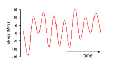
In high-cycle fatigue situations, materials performance is commonly characterized by an S-N curve, also known as a Wöhler curve . This is a graph of the magnitude of a cyclic stress (S) against the logarithmic scale of cycles to failure (N).

S-N curves are derived from tests on samples of the material to be characterized (often called coupons) where a regular sinusoidal stress is applied by a testing machine which also counts the number of cycles to failure. This process is sometimes known as coupon testing. Each coupon test generates a point on the plot though in some cases there is a runout where the time to failure exceeds that available for the test (see censoring). Analysis of fatigue data requires techniques from statistics, especially survival analysis and linear regression.
The progression of the S-N curve can be influenced by many factors such as corrosion, temperature, residual stresses, and the presence of notches. The Goodman-Line is a method used to estimate the influence of the mean stress on the fatigue strength.
Probabilistic nature of fatigue
As coupons sampled from a homogeneous frame will display a variation in their number of cycles to failure, the S-N curve should more properly be a Stress-Cycle-Probability (S-N-P) curve to capture the probability of failure after a given number of cycles of a certain stress. Probability distributions that are common in data analysis and in design against fatigue include the log-normal distribution, extreme value distribution, Birnbaum–Saunders distribution, and Weibull distribution.
Complex loadings
In practice, a mechanical part is exposed to a complex, often random, sequence of loads, large and small. In order to assess the safe life of such a part:
- Complex loading is reduced to a series of simple cyclic loadings using a technique such as rainflow analysis;
- A histogram of cyclic stress is created from the rainflow analysis to form a fatigue damage spectrum;
- For each stress level, the degree of cumulative damage is calculated from the S-N curve; and
- The effect of the individual contributions are combined using an algorithm such as Miner's rule.
For multiaxial loading
Since S-N curves are typically generated for uniaxial loading, some equivalence rule is needed whenever the loading is multiaxial. For simple, proportional loading histories (lateral load in a constant ratio with the axial), Sines rule may be applied. For more complex situations, such as nonproportional loading, Critical plane analysis must be applied.
Miner's Rule
In 1945, M A Miner popularised a rule that had first been proposed by A. Palmgren in 1924. The rule, variously called Miner's rule or the Palmgren-Miner linear damage hypothesis, states that where there are k different stress magnitudes in a spectrum, Si (1 ≤ i ≤ k), each contributing ni(Si) cycles, then if Ni(Si) is the number of cycles to failure of a constant stress reversal Si (determined by uni-axial fatigue tests), failure occurs when:

C is experimentally found to be between 0.7 and 2.2. Usually for design purposes, C is assumed to be 1. This can be thought of as assessing what proportion of life is consumed by a linear combination of stress reversals at varying magnitudes.
Though Miner's rule is a useful approximation in many circumstances, it has several major limitations:
- It fails to recognise the probabilistic nature of fatigue and there is no simple way to relate life predicted by the rule with the characteristics of a probability distribution. Industry analysts often use design curves, adjusted to account for scatter, to calculate Ni(Si).
- The sequence in which high vs. low stress cycles are applied to a sample in fact affect the fatigue life, for which Miner's Rule does not account. In some circumstances, cycles of low stress followed by high stress cause more damage than would be predicted by the rule. It does not consider the effect of an overload or high stress which may result in a compressive residual stress that may retard crack growth. High stress followed by low stress may have less damage due to the presence of compressive residual stress.
Paris' Law

In Fracture mechanics, Anderson, Gomez, and Paris derived relationships for the stage II crack growth with cycles N, in terms of the cyclical component ΔK of the Stress Intensity Factor K[13]

where a is the crack length and m is typically in the range 3 to 5 (for metals), which states that the rate of crack growth with respect to the cycles of load applied is a function of the stress intensity factor; this is named Paris' law.
This relationship was later modified (by Forman, 1967[14]) to make better allowance for the mean stress, by introducing a factor depending on (1-R) where R= min stress/max stress, in the denominator.
Goodman Relation
In the presence of a steady stress superimposed on the cyclic loading, the Goodman relation can be used to estimate a failure condition. It plots stress amplitude against mean stress with the fatigue limit and the ultimate tensile strength of the material as the two extremes. Alternative failure criteria include Soderberg and Gerber.[15]
Low-cycle fatigue
Where the stress is high enough for plastic deformation to occur, the accounting of the loading in terms of stress is less useful and the strain in the material offers a simpler and more accurate description. This type of fatigue is normally experienced by components which undergo a relatively small number of straining cycles. Low-cycle fatigue is usually characterised by the Coffin-Manson relation (published independently by L. F. Coffin in 1954[16] and S. S. Manson in 1953):[17]

where,
- Δεp /2 is the plastic strain amplitude;
- εf' is an empirical constant known as the fatigue ductility coefficient, the failure strain for a single reversal;
- 2N is the number of reversals to failure (N cycles);
- c is an empirical constant known as the fatigue ductility exponent, commonly ranging from -0.5 to -0.7 for metals in time independent fatigue. Slopes can be considerably steeper in the presence of creep or environmental interactions.
A similar relationship for materials such as Zirconium is used in the nuclear industry.[18]
Fatigue and fracture mechanics
The account above is purely empirical and, though it allows life prediction and design assurance, life improvement or design optimisation can be enhanced using Fracture mechanics. Fatigue of materials can be described as having four stages.
- Crack nucleation,
- Stage I crack-growth,
- Stage II crack-growth, and
- Ultimate ductile failure.
Design against fatigue
Dependable design against fatigue-failure requires thorough education and supervised experience in structural engineering, mechanical engineering, or materials science. There are four principal approaches to life assurance for mechanical parts that display increasing degrees of sophistication:[19]
- Design to keep stress below threshold of fatigue limit (infinite lifetime concept);
- Fail-safe, graceful degradation, and fault-tolerant design: Instruct the user to replace parts when they fail. Design in such a way that there is no single point of failure, and so that when any one part completely fails, it does not lead to catastrophic failure of the entire system.
- Safe-life design: Design (conservatively) for a fixed life after which the user is instructed to replace the part with a new one (a so-called lifed part, finite lifetime concept, or "safe-life" design practice); planned obsolescence and disposable product are variants that design for a fixed life after which the user is instructed to replace the entire device;
- Damage tolerant design: Instruct the user to inspect the part periodically for cracks and to replace the part once a crack exceeds a critical length. This approach usually uses the technologies of nondestructive testing and requires an accurate prediction of the rate of crack-growth between inspections. The designer sets some aircraft maintenance checks schedule frequent enough that parts are replaced while the crack is still in the "slow growth" phase. This is often referred to as damage tolerant design or "retirement-for-cause".
Stopping fatigue
Fatigue cracks that have begun to propagate can sometimes be stopped by drilling holes, called drill stops, in the path of the fatigue crack.[20] This is not recommended as a general practice because the hole represents a stress concentration factor which depends on the size of the hole and geometry, though the hole is typically less of a stress concentration than the removed tip of the crack. The possibility remains of a new crack starting in the side of the hole. It is always far better to replace the cracked part entirely.
Material change
Changes in the materials used in parts can also improve fatigue life. For example, parts can be made from better fatigue rated metals. Complete replacement and redesign of parts can also reduce if not eliminate fatigue problems. Thus helicopter rotor blades and propellers in metal are being replaced by composite equivalents. They are not only lighter, but also much more resistant to fatigue. They are more expensive, but the extra cost is amply repaid by their greater integrity, since loss of a rotor blade usually leads to total loss of the aircraft. A similar argument has been made for replacement of metal fuselages, wings and tails of aircraft.[21]
Peening treatment of welds and metal components
Increases in fatigue life and strength are proportionally related to the depth of the compressive residual stresses imparted by surface enhancement processes such as shot peening but particularly by laser peening. Shot peening imparts compressive residual stresses approximately 0.005 inches deep, laser peening imparts compressive residual stresses from 0.040 to 0.100 inches deep, or deeper. Laser peening provide significant fatigue life extension through shock wave mechanics which plastically deform the surface of the metal component changing the material properties.[22] Laser peening can be applied to existing parts without redesign requirements or incorporated into new designs to allow for lighter materials or thinner designs to achieve comparable engineering results.
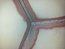
High frequency mechanical impact (HFMI) treatment of welds
The durability and life of dynamically loaded, welded steel structures are determined often by the welds, particular by the weld transitions. By selective treatment of weld transitions with the High Frequency Mechanical Impact (HFMI) treatment method,[23][24] the durability of many designs can be increased significantly. This method is universally applicable, requires only specific equipment and offers high reproducibility and a high degree of quality control.
Deep Cryogenic treatment
The use of Deep Cryogenic treatment has been shown to increase resistance to fatigue failure. Springs used in industry, auto racing and firearms have been shown to last up to six times longer when treated. Heat checking, which is a form of thermal cyclic fatigue has been greatly delayed.[25]
Notable fatigue failures
Versailles train crash
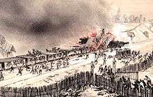
Following the King's fête celebrations at the Palace of Versailles, a train returning to Paris crashed in May 1842 at Meudon after the leading locomotive broke an axle. The carriages behind piled into the wrecked engines and caught fire. At least 55 passengers were killed trapped in the carriages, including the explorer Jules Dumont d'Urville. This accident is known in France as the "Catastrophe ferroviaire de Meudon". The accident was witnessed by the British locomotive engineer Joseph Locke and widely reported in Britain. It was discussed extensively by engineers, who sought an explanation.
The derailment had been the result of a broken locomotive axle. Rankine's investigation of broken axles in Britain highlighted the importance of stress concentration, and the mechanism of crack growth with repeated loading. His and other papers suggesting a crack growth mechanism through repeated stressing, however, were ignored, and fatigue failures occurred at an ever increasing rate on the expanding railway system. Other spurious theories seemed to be more acceptable, such as the idea that the metal had somehow "crystallized". The notion was based on the crystalline appearance of the fast fracture region of the crack surface, but ignored the fact that the metal was already highly crystalline.
de Havilland Comet

Two de Havilland Comet passenger jets broke up in mid-air and crashed within a few months of each other in 1954. As a result, systematic tests were conducted on a fuselage immersed and pressurised in a water tank. After the equivalent of 3,000 flights, investigators at the Royal Aircraft Establishment (RAE) were able to conclude that the crash had been due to failure of the pressure cabin at the forward Automatic Direction Finder window in the roof. This 'window' was in fact one of two apertures for the aerials of an electronic navigation system in which opaque fibreglass panels took the place of the window 'glass'. The failure was a result of metal fatigue caused by the repeated pressurisation and de-pressurisation of the aircraft cabin. Also, the supports around the windows were riveted, not bonded, as the original specifications for the aircraft had called for. The problem was exacerbated by the punch rivet construction technique employed. Unlike drill riveting, the imperfect nature of the hole created by punch riveting caused manufacturing defect cracks which may have caused the start of fatigue cracks around the rivet.

The Comet's pressure cabin had been designed to a safety factor comfortably in excess of that required by British Civil Airworthiness Requirements (2.5 times the cabin proof test pressure as opposed to the requirement of 1.33 times and an ultimate load of 2.0 times the cabin pressure) and the accident caused a revision in the estimates of the safe loading strength requirements of airliner pressure cabins.
In addition, it was discovered that the stresses around pressure cabin apertures were considerably higher than had been anticipated, especially around sharp-cornered cut-outs, such as windows. As a result, all future jet airliners would feature windows with rounded corners, greatly reducing the stress concentration. This was a noticeable distinguishing feature of all later models of the Comet. Investigators from the RAE told a public inquiry that the sharp corners near the Comets' window openings acted as initiation sites for cracks. The skin of the aircraft was also too thin, and cracks from manufacturing stresses were present at the corners.
Alexander L. Kielland oil platform capsizing
The Alexander L. Kielland was a Norwegian semi-submersible drilling rig that capsized whilst working in the Ekofisk oil field in March 1980 killing 123 people. The capsizing was the worst disaster in Norwegian waters since World War II. The rig, located approximately 320 km east of Dundee, Scotland, was owned by the Stavanger Drilling Company of Norway and was on hire to the United States company Phillips Petroleum at the time of the disaster. In driving rain and mist, early in the evening of 27 March 1980 more than 200 men were off duty in the accommodation on the Alexander L. Kielland. The wind was gusting to 40 knots with waves up to 12 m high. The rig had just been winched away from the Edda production platform. Minutes before 18:30 those on board felt a 'sharp crack' followed by 'some kind of trembling'. Suddenly the rig heeled over 30° and then stabilised. Five of the six anchor cables had broken, with one remaining cable preventing the rig from capsizing. The list continued to increase and at 18.53 the remaining anchor cable snapped and the rig turned upside down.
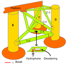
A year later in March 1981, the investigative report[27] concluded that the rig collapsed owing to a fatigue crack in one of its six bracings (bracing D-6), which connected the collapsed D-leg to the rest of the rig. This was traced to a small 6 mm fillet weld which joined a non-load-bearing flange plate to this D-6 bracing. This flange plate held a sonar device used during drilling operations. The poor profile of the fillet weld contributed to a reduction in its fatigue strength. Further, the investigation found considerable amounts of lamellar tearing in the flange plate and cold cracks in the butt weld. Cold cracks in the welds, increased stress concentrations due to the weakened flange plate, the poor weld profile, and cyclical stresses (which would be common in the North Sea), seemed to collectively play a role in the rig's collapse.
Others
- The 1862 Hartley Colliery Disaster was caused by the fracture of a steam engine beam and killed 220 people.
- The 1919 Great Molasses Flood has been attributed to a fatigue failure.
- The 1948 Northwest Airlines Flight 421 crash due to fatigue failure in a wing spar root
- The 1957 "Mt. Pinatubo", presidential plane of Philippine President Ramon Magsaysay, crashed due to engine failure caused by metal fatigue.
- The 1965 capsize of the UK's first offshore oil platform, the Sea Gem, was due to fatigue in part of the suspension system linking the hull to the legs.
- The 1968 Los Angeles Airways Flight 417 lost one of its main rotor blades due to fatigue failure.
- The 1968 MacRobertson Miller Airlines Flight 1750 that lost a wing due to improper maintenance leading to fatigue failure
- The 1977 Dan-Air Boeing 707 crash caused by fatigue failure resulting in the loss of the right horizontal stabilizer
- The 1980 LOT Flight 7 that crashed due to fatigue in an engine turbine shaft resulting in engine disintegration leading to loss of control
- The 1985 Japan Airlines Flight 123 crashed after the aircraft lost its vertical stabilizer due to faulty repairs on the rear bulkhead.
- The 1988 Aloha Airlines Flight 243 suffered an explosive decompression due to fatigue failure.
- The 1989 United Airlines Flight 232 lost its tail engine due to fatigue failure in a fan disk hub.
- The 1992 El Al Flight 1862 lost both engines on its right-wing due to fatigue failure in the pylon mounting of the #3 Engine.
- The 1998 Eschede train disaster was caused by fatigue failure of a single composite wheel.
- The 2000 Hatfield rail crash was likely caused by rolling contact fatigue.
- The 2000 recall of 6.5 million Firestone tires on Ford Explorers originated from fatigue crack growth leading to separation of the tread from the tire.[28]
- The 2002 China Airlines Flight 611 had disintegrated in-flight due to fatigue failure.
- The 2005 Chalk's Ocean Airways Flight 101 lost its right wing due to fatigue failure brought about by inadequate maintenance practices.
- The 2009 Viareggio train derailment due to fatigue failure.
See also
- Aviation safety
- Embedment
- Forensic materials engineering
- Fractography
- Thermo-mechanical fatigue
- Critical plane analysis
- Vibration fatigue
References
- ↑ Kim, W.H.; Laird, C. (1978). Crack Nucleation and State I Propagation in High Strain Fatigue- II Mechanism. Acta Metallurgica. pp. 789–799.
- ↑ Stephens, Ralph I.; Fuchs, Henry O. (2001). Metal Fatigue in Engineering (Second ed.). John Wiley & Sons, Inc. p. 69. ISBN 0-471-51059-9.
- ↑ Bathias, C. (1999). "There is no infinite fatigue life in metallic materials". Fatigue & Fracture of Engineering Materials & Structures. 22 (7): 559–565. doi:10.1046/j.1460-2695.1999.00183.x.
- ↑ Joseph E. Shigley; Charles R. Mischke; Richard G. Budynas. Mechanical Engineering Design (7th ed.). McGraw Hill Higher Education. ISBN 9780072520361.
- ↑ A. Bäumel, Jr and T. Seeger (1990). Materials data for cyclic loading, supplement 1. Elsevier. ISBN 978-0-444-88603-3.
- ↑ S. Korkmaz (2010). Uniform Material Law: Extension to High-Strength Steels. VDM. ISBN 978-3-639-25625-3.
- ↑ Korkmaz, S. (2011). "A Methodology to Predict Fatigue Life of Cast Iron: Uniform Material Law for Cast Iron". Journal of Iron and Steel Research, International. 18: 8. doi:10.1016/S1006-706X(11)60102-7.
- ↑ N.A. Fleck, C.S. Shin, and R.A. Smith. "Fatigue Crack Growth Under Compressive Loading". Engineering Fracture Mechanics, 1985, vol 21, No 1, pp. 173-185.
- 1 2 Schutz, W. (1996). "A history of fatigue". Engineering Fracture Mechanics. 54: 263–300. doi:10.1016/0013-7944(95)00178-6.
- ↑ W.J.M. Rankine. (1842). "On the causes of the unexpected breakage of the journals of railway axles, and on the means of preventing such accidents by observing the law of continuity in their construction". Institution of Civil Engineers, Minutes of Proceedings, 105-108.
- ↑ F. Braithwaite. (1854). "On the fatigue and consequent fracture of metals". Institution of Civil Engineers, Minutes of Proceedings, 463–474.
- ↑ Matsuishi, M., Endo, T., 1968, Fatigue of Metals Subjected to Varying Stress, Japan Society of Mechanical Engineers, Jukvoka, Japan.
- ↑ P. C. Paris, M. P. Gomez and W. E. Anderson. A rational analytic theory of fatigue. The Trend in Engineering (1961). 13, 9-14.
- ↑
- ↑ http://www.roymech.co.uk/Useful_Tables/Fatigue/Stress_levels.html
- ↑ Coffin Jr., L.F. (1954). "A study of the effects of cyclic thermal stresses on a ductile metal", Trans. ASME, Vol. 76, pp. 931-950.
- ↑ Manson, S.S. (1953). NACA TN-2933 "Behavior of materials under conditions of thermal stress". National Advisory Committee for Aeronautics.
- ↑ O'Donnell, W.J.; Langer, B.F. (1964). Nuclear Science and Engineering. 20: 1–12. Missing or empty
|title=(help) - ↑ Tapany Udomphol. "Fatigue of metals", p. 54. sut.ac.th, 2007.
- ↑ http://www.prnewswire.com/news-releases/material-technologies-inc-completes-efs-inspection-of-bridge-in-new-jersey-58419432.html "Material Technologies, Inc. Completes EFS Inspection of Bridge in New Jersey". Press release regarding metal fatigue damage to the Manahawkin Bay Bridge in New Jersey
- ↑ "Horrors in the Skies." Popular Mechanics, June 1989, pp. 67-70.
- ↑ https://engineering.purdue.edu/LAMPL/research_peening.html
- ↑ Can Yıldırım, Halid; Marquis, Gary. "Fatigue strength improvement factors for high strength steel welded joints treated by high frequency mechanical impact". International Journal of Fatigue. 44: 168–176. doi:10.1016/j.ijfatigue.2012.05.002.
- ↑ Can Yıldırım, Halid; Marquis, Gary; Barsoum, Zuheir. "Fatigue assessment of High Frequency Mechanical Impact (HFMI)-improved fillet welds by local approaches". International Journal of Fatigue. 52: 57–67. doi:10.1016/j.ijfatigue.2013.02.014.
- ↑ https://www.cryogenictreatmentdatabase.org/?cat_ID=220&s=fatigue
- ↑ "ObjectWiki: Fuselage of de Havilland Comet Airliner G-ALYP". Science Museum. 24 September 2009. Archived from the original on January 7, 2009. Retrieved 9 October 2009.
- ↑ The Alexander L. Kielland accident, Report of a Norwegian public commission appointed by royal decree of March 28, 1980, presented to the Ministry of Justice and Police March, 1981 ISBN B0000ED27N
- ↑ ANSBERRY, CLARE (Feb 5, 2001). "In Firestone Tire Study, Expert Finds Vehicle Weight Was Key in Failure". Wall Street Journal. Retrieved 6 September 2016.
Further reading
- Andrew, W. (1995) Fatigue and Tribological Properties of Plastics and Elastomers, ISBN 1-884207-15-4.
- Leary, M., Burvill, C. Applicability of published data for fatigue-limited design Quality and Reliability Engineering International Volume 25, Issue 8, 2009.
- Dieter, G.E. (1988) Mechanical Metallurgy, ISBN 0-07-100406-8.
- Little, R.E. & Jebe, E. H. (1975) Statistical design of fatigue experiments ISBN 0-470-54115-6.
- Palmgren, A.G. (1924): Die Lebensdauer von Kugellagern (Life Length of Roller Bearings. In German). Zeitschrift des Vereines Deutscher Ingenieure (VDI Zeitschrift), ISSN 0341-7258 (Warning: Check ISSN), Vol 68, No 14, April 1924, pp. 339–341.
- Schijve, J. (2009). Fatigue of Structures and Materials, 2nd Edition with Cd-Rom. Springer. ISBN 978-1-4020-6807-2.
- Lalanne, C. (2009). Fatigue Damage. ISTE - Wiley. ISBN 978-1-84821-125-4.
- Pook, Les (2007). Metal Fatigue, What it is, why it matters. Springer. ISBN 978-1-4020-5596-6.
- Draper, John (2008). Modern Metal Fatigue Analysis. EMAS. ISBN 0-947817-79-4.
- Subra Suresh, Fatigue of Materials, Second Edition, Cambridge University Press, 1998, ISBN 0-521-57046-8.
External links
| Wikimedia Commons has media related to Material fatigue. |
- Fatigue by Shawn M. Kelly
- SAE Fatigue, Design, and Evaluation Committee website
- Article regarding Fatigue Testing of Bolted Joints
- Examples of fatigued metal products
- A collection of fatigue knowledge and calculators
- MATDAT.COM - Material Properties Database - Monotonic, Cyclic and Fatigue Properties of Steels, Aluminum and Titanium Alloys
- Application note on fatigue crack propagation in UHMWPE
- Video on the fatigue test, Karlsruhe University of Applied Sciences