Thermionic emission
Thermionic emission is the thermally induced flow of charge carriers from a surface or over a potential-energy barrier. This occurs because the thermal energy given to the carrier overcomes the work function of the material. The charge carriers can be electrons or ions, and in older literature are sometimes referred to as "thermions". After emission, a charge that is equal in magnitude and opposite in sign to the total charge emitted is initially left behind in the emitting region. But if the emitter is connected to a battery, the charge left behind is neutralized by charge supplied by the battery as the emitted charge carriers move away from the emitter, and finally the emitter will be in the same state as it was before emission.
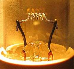
The classical example of thermionic emission is the emission of electrons from a hot cathode into a vacuum (also known as thermal electron emission or the Edison effect) in a vacuum tube. The hot cathode can be a metal filament, a coated metal filament, or a separate structure of metal or carbides or borides of transition metals. Vacuum emission from metals tends to become significant only for temperatures over 1,000 K (730 °C; 1,340 °F).
The term "thermionic emission" is now also used to refer to any thermally-excited charge emission process, even when the charge is emitted from one solid-state region into another. This process is crucially important in the operation of a variety of electronic devices and can be used for electricity generation (such as thermionic converters and electrodynamic tethers) or cooling. The magnitude of the charge flow increases dramatically with increasing temperature.
History

Because the electron was not identified as a separate physical particle until the 1897 work of J. J. Thomson, the word "electron" was not used when discussing experiments that took place before this date.
The phenomenon was initially reported in 1853 by Edmond Becquerel.[1][2] It was rediscovered in 1873 by Frederick Guthrie in Britain.[3] While doing work on charged objects, Guthrie discovered that a red-hot iron sphere with a negative charge would lose its charge (by somehow discharging it into air). He also found that this did not happen if the sphere had a positive charge.[4] Other early contributors included Johann Wilhelm Hittorf (1869–1883),[5] Eugen Goldstein (1885),[6] and Julius Elster and Hans Friedrich Geitel (1882–1889).[7]
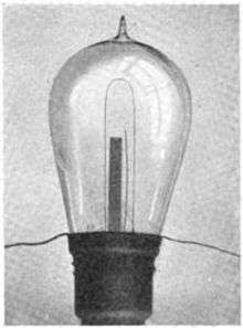
The effect was rediscovered again by Thomas Edison on February 13, 1880, while trying to discover the reason for breakage of lamp filaments and uneven blackening (darkest near the positive terminal of the filament) of the bulbs in his incandescent lamps.
Edison built several experimental lamp bulbs with an extra wire, metal plate, or foil inside the bulb that was separate from the filament and thus could serve as an electrode. He connected a galvanometer, a device used to measure current (the flow of charge), to the output of the extra metal electrode. If the foil was put at a negative potential relative to the filament, there was no measurable current between the filament and the foil. When the foil was raised to a positive potential relative to the filament, there could be a significant current between the filament through the vacuum to the foil if the filament was heated sufficiently (by its own external power source).
We now know that the filament was emitting electrons, which were attracted to a positively charged foil, but not a negatively charged one. This one-way current was called the Edison effect (although the term is occasionally used to refer to thermionic emission itself). He found that the current emitted by the hot filament increased rapidly with increasing voltage, and filed a patent application for a voltage-regulating device using the effect on November 15, 1883 (U.S. patent 307,031,[8] the first US patent for an electronic device). He found that sufficient current would pass through the device to operate a telegraph sounder. This was exhibited at the International Electrical Exposition in Philadelphia in September 1884. William Preece, a British scientist, took back with him several of the Edison effect bulbs. He presented a paper on them in 1885, where he referred to thermionic emission as the "Edison Effect."[9][10] The British physicist John Ambrose Fleming, working for the British "Wireless Telegraphy" Company, discovered that the Edison Effect could be used to detect radio waves. Fleming went on to develop the two-element vacuum tube known as the diode, which he patented on November 16, 1904.[11]
The thermionic diode can also be configured as a device that converts a heat difference to electric power directly without moving parts (a thermionic converter, a type of heat engine).
Richardson's law
Following J. J. Thomson's identification of the electron in 1897, the British physicist Owen Willans Richardson began work on the topic that he later called "thermionic emission". He received a Nobel Prize in Physics in 1928 "for his work on the thermionic phenomenon and especially for the discovery of the law named after him".
From band theory, there are one or two electrons per atom in a solid that are free to move from atom to atom. This is sometimes collectively referred to as a "sea of electrons". Their velocities follow a statistical distribution, rather than being uniform, and occasionally an electron will have enough velocity to exit the metal without being pulled back in. The minimum amount of energy needed for an electron to leave a surface is called the work function. The work function is characteristic of the material and for most metals is on the order of several electronvolts. Thermionic currents can be increased by decreasing the work function. This often-desired goal can be achieved by applying various oxide coatings to the wire.
In 1901 Richardson published the results of his experiments: the current from a heated wire seemed to depend exponentially on the temperature of the wire with a mathematical form similar to the Arrhenius equation.[12] Later, he proposed that the emission law should have the mathematical form[13]

where J is the emission current density, T is the temperature of the metal, W is the work function of the metal, k is the Boltzmann constant, and AG is a parameter discussed next.
In the period 1911 to 1930, as physical understanding of the behaviour of electrons in metals increased, various theoretical expressions (based on different physical assumptions) were put forwards for AG, by Richardson, Saul Dushman, Ralph H. Fowler, Arnold Sommerfeld and Lothar Wolfgang Nordheim. Over 60 years later, there is still no consensus amongst interested theoreticians as to what is the exact expression of AG, but there is agreement that AG must be written in the form

where λR is a material-specific correction factor that is typically of order 0.5, and A0 is a universal constant given by[13]

where m and −e are the mass and charge of an electron, and h is Planck's constant.
In fact, by about 1930 there was agreement that, due to the wave-like nature of electrons, some proportion rav of the outgoing electrons would be reflected as they reached the emitter surface, so the emission current density would be reduced, and λR would have the value (1-rav). Thus, one sometimes sees the thermionic emission equation written in the form
- .

However, a modern theoretical treatment by Modinos assumes that the band-structure of the emitting material must also be taken into account. This would introduce a second correction factor λB into λR, giving . Experimental values for the "generalized" coefficient AG are generally of the order of magnitude of A0, but do differ significantly as between different emitting materials, and can differ as between different crystallographic faces of the same material. At least qualitatively, these experimental differences can be explained as due to differences in the value of λR.

Considerable confusion exists in the literature of this area because: (1) many sources do not distinguish between AG and A0, but just use the symbol A (and sometimes the name "Richardson constant") indiscriminately; (2) equations with and without the correction factor here denoted by λR are both given the same name; and (3) a variety of names exist for these equations, including "Richardson equation", "Dushman's equation", "Richardson–Dushman equation" and "Richardson–Laue–Dushman equation". In the literature, the elementary equation is sometimes given in circumstances where the generalized equation would be more appropriate, and this in itself can cause confusion. To avoid misunderstandings, the meaning of any "A-like" symbol should always be explicitly defined in terms of the more fundamental quantities involved.
Because of the exponential function, the current increases rapidly with temperature when kT is less than W. (For essentially every material, melting occurs well before kT = W.)
Schottky emission
In electron emission devices, especially electron guns, the thermionic electron emitter will be biased negative relative to its surroundings. This creates an electric field of magnitude F at the emitter surface. Without the field, the surface barrier seen by an escaping Fermi-level electron has height W equal to the local work-function. The electric field lowers the surface barrier by an amount ΔW, and increases the emission current. This is known as the Schottky effect (named for Walter H. Schottky) or field enhanced thermionic emission. It can be modeled by a simple modification of the Richardson equation, by replacing W by (W − ΔW). This gives the equation[14][15]


where ε0 is the electric constant (also, formerly, called the vacuum permittivity).
Electron emission that takes place in the field-and-temperature-regime where this modified equation applies is often called Schottky emission. This equation is relatively accurate for electric field strengths lower than about 108 V m−1. For electric field strengths higher than 108 V m−1, so-called Fowler-Nordheim (FN) tunneling begins to contribute significant emission current. In this regime, the combined effects of field-enhanced thermionic and field emission can be modeled by the Murphy-Good equation for thermo-field (T-F) emission.[16] At even higher fields, FN tunneling becomes the dominant electron emission mechanism, and the emitter operates in the so-called "cold field electron emission (CFE)" regime.
Thermionic emission can also be enhanced by interaction with other forms of excitation such as light.[17] For example, excited Cs-vapours in thermionic converters form clusters of Cs-Rydberg matter which yield a decrease of collector emitting work function from 1.5 eV to 1.0–0.7 eV. Due to long-lived nature of Rydberg matter this low work function remains low which essentially increases the low-temperature converter’s efficiency.[18]
Photon-enhanced thermionic emission
Photon-enhanced thermionic emission (PETE) is a process developed by scientists at Stanford University that harnesses both the light and heat of the sun to generate electricity and increases the efficiency of solar power production by more than twice the current levels. The device developed for the process reaches peak efficiency above 200 °C, while most silicon solar cells become inert after reaching 100 °C. Such devices work best in parabolic dish collectors, which reach temperatures up to 800 °C. Although the team used a gallium nitride semiconductor in its proof-of-concept device, it claims that the use of gallium arsenide can increase the device's efficiency to 55–60 percent, nearly triple that of existing systems,[19][20] and 12–17 percent more than existing 43 percent multi-junction solar cells.[21]
Thermionic emission from graphene
Compared with the traditional bulk metal or semiconductor materials, graphene has many unique and excellent properties, such as atomic layer thickness, linear band structure near Dirac cone, ultrahigh Fermi velocity, etc., making traditional Richardson's law derived for bulk materials invalid for graphene. Researchers from Singapore University of Technology and Design have proposed that there exists a new scaling of thermionic emission from a single-layer graphene which has been verified with an experiment.[22] They also proposed that graphene-based vacuum thermionic energy converter has an efficiency of about 45%, with cathode temperature ranging from 700 K to 900 K, which is greatly reduced compared to the traditional thermionic converter of above 1200 K and has a promising application in recycling the waste heat from industrial processes.[23]
See also
- Space charge, work function — key physics concepts that influence thermionic emission.
- Hot cathode — article describing construction and behaviour of practical thermionic cathodes.
- Thermionic converter — a type of heat engine that directly produces electrical power via thermionic emission.
- Vacuum tube, X-ray tube, fluorescent lamp, cathode ray tube — vacuum electronic devices that typically use a thermionic cathode as an electron source.
- Thermoelectric effect — not to be confused with thermionic emission, thermoelectricity is the thermal generation of electric currents within solid conductors.
References
- ↑ http://etd.library.vanderbilt.edu/available/etd-03262013-131559/unrestricted/Paxton_Thesis.pdf
- ↑ https://www.britannica.com/technology/thermionic-power-converter
- ↑ See:
- Guthrie, Frederick (October 1873). "On a relation between heat and static electricity". The London, Edinburgh and Dublin Philosophical Magazine and Journal of Science. 4th. 46: 257–266.
- Guthrie, Frederick (February 13, 1873). "On a new relation between heat and electricity". Proceedings of the Royal Society of London. 21: 168–169. doi:10.1098/rspl.1872.0037.
- ↑ Richardson, O. W. (2003). Thermionic Emission from Hot Bodies. Wexford College Press. p. 196. ISBN 978-1-929148-10-3.
- ↑ See:
- Hittorf, W. (1869). "Ueber die Electricitätsleitung der Gase" [On electrical conduction of gases]. Annalen der Physik und Chemie. 2nd series (in German). 136 (1): 1–31.
- Hittorf, W. (1869). "Ueber die Electricitätsleitung der Gase" [On electrical conduction of gases]. Annalen der Physik und Chemie. 2nd series (in German). 136: 197–234.
- Hittorf, W. (1874). "Ueber die Electricitätsleitung der Gase" [On electrical conduction of gases]. Annalen der Physik und Chemie (in German). Jubalband (anniversary volume): 430–445.
- Hittorf, W. (1879). "Ueber die Electricitätsleitung der Gase" [On electrical conduction of gases]. Annalen der Physik und Chemie. 3rd series (in German). 7: 553–631.
- Hittorf, W. (1883). "Ueber die Electricitätsleitung der Gase" [On electrical conduction of gases]. Annalen der Physik und Chemie. 3rd series (in German). 20: 705–755.
- Hittorf, W. (1884). "Ueber die Electricitätsleitung der Gase" [On electrical conduction of gases]. Annalen der Physik und Chemie. 3rd series (in German). 21: 90–139.
- ↑ E. Goldstein (1885) "Ueber electrische Leitung in Vacuum" (On electric conduction in vacuum) Annalen der Physik und Chemie, 3rd series, 24 : 79-92.
- ↑ See:
- Elster and Geitel (1882) "Ueber die Electricität der Flamme" (On the electricity of flames), Annalen der Physik und Chemie, 3rd series, 16 : 193-222.
- Elster and Geitel (1883) "Ueber Electricitätserregung beim Contact von Gasen und glühenden Körpern" (On the generation of electricity by the contact of gases and incandescent bodies), Annalen der Physik und Chemie, 3rd series, 19 : 588-624.
- Elster and Geitel (1885) "Ueber die unipolare Leitung erhitzter Gase" (On the unipolar conductivity of heated gases") Annalen der Physik und Chemie, 3rd series, 26 : 1-9.
- Elster and Geitel (1887) "Ueber die Electrisirung der Gase durch glühende Körper" (On the electrification of gases by incandescent bodies") Annalen der Physik und Chemie, 3rd series, 31 : 109-127.
- Elster and Geitel (1889) "Ueber die Electricitätserregung beim Contact verdünnter Gase mit galvanisch glühenden Drähten" (On the generation of electricity by contact of rarefied gas with electrically heated wires) Annalen der Physik und Chemie, 3rd series, 37 : 315-329.
- ↑ US 307031, Edison, Thomas A., "Electrical indicator", published November 15, 1883, issued October 21, 1884
- ↑ Preece, William Henry (1885). "On a peculiar behaviour of glow lamps when raised to high incandescence". Proceedings of the Royal Society of London. 38: 219–230. doi:10.1098/rspl.1884.0093. Preece coins the term the "Edison effect" on page 229.
- ↑ Josephson, M. (1959). Edison. McGraw-Hill. ISBN 0-07-033046-8.
- ↑ See:
- Provisional specification for a thermionic valve was lodged on November 16, 1904. In this document, Fleming coined the British term "valve" for what in North America is called a "vacuum tube": "The means I employ for this purpose consists in the insertion in the circuit of the alternating current of an appliance which permits only the passage of electric current in one direction and constitutes therefore an electrical valve."
- GB 190424850, Fleming, John Ambrose, "Improvements in instruments for detecting and measuring alternating electric currents", published August 15, 1905, issued September 21, 1905
- US 803684, Fleming, John Ambrose, "Instrument for converting alternating electric currents into continuous currents", published April 29, 1905, issued November 7, 1905
- ↑ O. W. Richardson (1901) "On the negative radiation from hot platinum," Philosophical of the Cambridge Philosophical Society, 11 : 286-295.
- 1 2 Crowell, C. R. (1965). "The Richardson constant for thermionic emission in Schottky barrier diodes". Solid-State Electronics. 8 (4): 395–399. Bibcode:1965SSEle...8..395C. doi:10.1016/0038-1101(65)90116-4.
- ↑ Kiziroglou, M. E.; Li, X.; Zhukov, A. A.; De Groot, P. A. J.; De Groot, C. H. (2008). "Thermionic field emission at electrodeposited Ni-Si Schottky barriers". Solid-State Electronics. 52 (7): 1032–1038. Bibcode:2008SSEle..52.1032K. doi:10.1016/j.sse.2008.03.002.
- ↑ Orloff, J. (2008). "Schottky emission". Handbook of Charged Particle Optics (2nd ed.). CRC Press. pp. 5–6. ISBN 978-1-4200-4554-3.
- ↑ Murphy, E. L.; Good, G. H. (1956). "Thermionic Emission, Field Emission, and the Transition Region". Physical Review. 102 (6): 1464–1473. Bibcode:1956PhRv..102.1464M. doi:10.1103/PhysRev.102.1464.
- ↑ Mal'Shukov, A. G.; Chao, K. A. (2001). "Opto-Thermionic Refrigeration in Semiconductor Heterostructures". Physical Review Letters. 86 (24): 5570–5573. Bibcode:2001PhRvL..86.5570M. doi:10.1103/PhysRevLett.86.5570.
- ↑ Svensson, R.; Holmlid, L. (1992). "Very low work function surfaces from condensed excited states: Rydber matter of cesium". Surface Science. 269/270: 695–699. Bibcode:1992SurSc.269..695S. doi:10.1016/0039-6028(92)91335-9.
- ↑ Bergeron, L. (2 August 2010). "New solar energy conversion process discovered by Stanford engineers could revamp solar power production". Stanford Report. Retrieved 2010-08-04.
- ↑ Schwede, J. W.; et al. (2010). "Photon-enhanced thermionic emission for solar concentrator systems". Nature Materials. 9 (9): 762. Bibcode:2010NatMa...9..762S. doi:10.1038/nmat2814.
- ↑ Green, M. A.; Emery, K.; Hishikawa, Y.; Warta, W. (2011). "Solar cell efficiency tables (version 37)". Progress in Photovoltaics: Research and Applications. 19 (1): 84. doi:10.1002/pip.1088.
- ↑ Liang, Shi-Jun; Ang, L. K. (2015). "Electron Thermionic Emission from Graphene and a Thermionic Energy Converter". Physical Review Applied. 3 (1): 014002. arXiv:1501.05056
 . Bibcode:2015PhRvP...3a4002L. doi:10.1103/PhysRevApplied.3.014002.
 - ↑ Millikin, M. (9 March 2015). "SUTD team proposes low-temperature thermionic converter with graphene cathode; about 45% efficiency". Green Car Congress Report.
External links
- How vacuum tubes really work with a section on thermionic emission, with equations, john-a-harper.com.
- Owen Richardson's Nobel lecture on thermionics, nobel.se, December 12, 1929. (PDF)
- Derivations of thermionic emission equations from an undergraduate lab, csbsju.edu.