Tip and ring
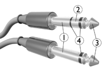
Tip and ring are the names of the two conductors or sides of a telephone line. The terms originate in reference to the telephone plugs used for connecting telephone calls in manual switchboards. One side of the line is connected to the metal tip of the plug, and the second is connected to a metal ring behind the tip, separated and insulated from the tip by a non-conducting material. When inserted into a jack, the plug's tip conductor connects first, followed by the ring conductor. In many European countries tip and ring are referred to as the A and B wires.
The ring conductor has a direct current (DC) potential of −48V to −52V with respect to tip conductor when the line is in the on-hook (idle) state. Neither conductor is referenced to ground. Floating both conductors (not referencing either one to ground) minimizes the pickup of hum from any nearby alternating current (AC) power wires.
Origin
The terms tip and ring originated in the early days of telephony when telephone operators used plugs to connect customer calls. They are named after the parts of the plug to which the wires were connected. The words are often abbreviated as T and R.
Line voltage
The telephone company maintains large battery systems that supply DC line voltage for the operation of analog telephone service ("plain old telephone service", or POTS) at customer locations. The voltage supplied is a compromise between operational needs for reliable service and safety precautions for customers and service personnel. The length of the line to a customer telephone interface presents a resistance across which the central office voltage experiences a drop and therefore the voltage at the customer site may vary. The nominal battery voltage is 52.1 V, based on a 24-cell lead-acid battery.[1] The voltage at a subscriber's network interface is typically 48 V.
In the middle 20th century, long loops in many rural areas of North America used range extenders, which operated at 100 or 130 volts to ensure reliable signaling. Some rural switching systems were designed to apply range extenders internally and thus share a few extenders among many lines, while for other lines, one extender was applied externally per line.
Originally, the potentials on the wires were positive with respect to earth (ground). Telephone companies discovered that with positive voltage on the copper wires, copper wires experienced corrosion due to electrolysis. Operating in reverse, with a negative potential on the wires, the copper is protected from corrosion by cathodic protection.
To ring the telephone to alert a subscriber to an incoming call, about 90 volts of 20 Hz AC current is superimposed over the DC voltage already present on the idle line. Historically a variety of frequencies have been used, however.
Polarity
In the early years of the telephone industry when rotary dial instruments were in use, the correct polarity of tip and ring was important only for properly ringing a telephone, especially in party line service with selective ringing, and for correctly identifying the calling customer on certain party lines for toll calls.
When Touch-Tone service was introduced in the 1960s, the dual-tone multi-frequency signaling (DTMF) tone generator also required correct polarity as it depended on the line power for operation. Later Touch-Tone telephones included a diode bridge that eliminated the polarity sensitivity, so that consumer telephone service is essentially immune to reversal today. However, some special circuits, such as some direct inward dialing (DID) trunks, T-1 lines, and ground start lines connected to field side (terminal) equipment, e.g., a corporate private branch exchange (PBX) switch, correctly operate only with proper tip and ring polarity.
Color code
When simple on-premises wiring is color-coded, two-wire telephone plugs or the first pair of a multi-pair connector commonly have the tip wire coded green and ring coded red. In four wire plugs, the second pair has black tip and yellow ring. A third pair consists of white tip and blue ring. For larger cable assemblies more complex schemes such as the 25-pair color code are used.
Telephone technicians often used the phrase "red-right-ring-rear" (or "ring-right-red-rough") to remember that the red wire connects to the right-side post in the wall jack and to the ring on the plug and to the rear lug on main distribution frames. Sometimes "rough" or "ridge" was added for jumper wires with a tactile code.
References
- ↑ W.D. Reeve, Subscriber Loop Signaling and Transmission Handbook—Analog, IEEE Press (1992), p.138