English wheel
The English wheel, in Britain also known as a wheeling machine, is a metalworking tool that enables a craftsperson to form compound (double curvature) curves from flat sheets of metal such as aluminium or steel.[1][2]
Description
The process of using an English wheel is known as wheeling. Panels produced this way are expensive, due to the highly skilled and labour-intensive production method, but it has the key advantage that it can flexibly produce different panels using the same machine. It is a forming machine that works by surface stretching and is related in action to panel beating processes. It is used wherever low volumes of compound curved panels are required; typically in coachbuilding, car restoration, spaceframe chassis racing cars that meet regulations that require sheetmetal panels resembling mass production vehicles (NASCAR),[3][4] car prototypes and aircraft skin components. English wheel production is at its highest in low-volume sports car production, particularly when more easily formed aluminium alloy is used.
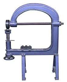
Where high-volume production runs of panels are required, the wheel is replaced by a stamping press that has a much higher capital setup cost and longer development time than using an English wheel, but each panel in the production run can be produced in a matter of seconds. This cost is defrayed across a larger production run, but a stamping press is limited to only one model of panel per set of dies. The English wheel model shown is manually operated, but when used on thicker sheet metals such as for ship hulls the machine may be powered and much larger than the one shown here.
Construction
The machine is shaped like a large, closed letter "C". At the ends of the C, there are two wheels. The wheel on the top is called the rolling wheel, while the wheel on the bottom is called the anvil wheel. (Some references refer to the wheels by their position: upper wheel and lower wheel.) The anvil wheel usually has a smaller radius than the rolling wheel. Although larger machines exist, the rolling wheel is usually 8 cm (3 inches) wide or less, and usually 25 cm (9 inches) in diameter, or less.
The rolling (top) wheel is flat in cross section, while the anvil (bottom) wheel is domed.
The depth of the C-shaped frame is called the throat. The largest machines have throat sizes of 120 cm (48 inches), while smaller machines have throat sizes of about 60 cm (24 inches). The C stands vertically and is supported by a frame. The throat size usually determines the largest size of metal sheet that the operator can place in the machine and work easily. On some machines, the operator can turn the top wheel and anvil 90 degrees to the frame to increase the maximum size of the work piece. Because the machine works by an amount of pressure between the wheels through the material, and because that pressure changes as the material becomes thinner, the lower jaw and cradle of the frame that holds the anvil roller is adjustable. It may move with a hydraulic jack on machines designed for steel plate, or a jackscrew on machines designed for sheet metals. As the material thins, the operator must adjust the pressure to compensate.
Frame designs are the most significant element of this simple device. For the most part wheels have changed very little since the 19th century. The early English machines (as opposed to the American versions), such as Edwards, Kendrick, Brown, Boggs, and Ranalah, etc., had cast iron frames. These wheels, made during the 19th Century, had Babbitt metal plain bearings, making them difficult to push and pull the metal through when operated at high pressures. Later, when ball bearings came into use, the machines became more suitable for hard and thick material, such as 1/8” steel. Despite the advantages of cast iron, it has less than half the stiffness (Young's modulus) of steel and sometimes must be replaced by steel when a stiffer frame is needed. Steel frames made of solid flame-cut plate, or frames built-up of cut-and-welded plates, are common designs. Steel tubing, generally of square section, has been used for wheeling machine frames during the past 30 years, in the US particularly, where sheet metal shaping has become a hobby as well as a business. Tube-framed machines are reasonably-priced and are available either as kit-built machines (or can be built easily from plans). The stiffest tubular frames have a fully triangulated external bracing truss. They are most effective on thinner or softer materials, such as 20 ga steel or .063" aluminum.[5] Cast frame machines, like the one pictured, are still available.
A properly equipped machine has an assortment of anvil wheels. Anvil wheels, like dollies used with hammers in panel beating (which are also known as anvils) should be used to match the desired crown or curvature of the work piece.
Operation
The operator of the machine passes the sheet metal between the anvil wheel and the rolling wheel. This process stretches the material and causes it to become thinner. As the material stretches, it forms a convex surface over the anvil wheel.[6] This surface is known as "crown". A high crown surface is very curved, a low crown surface is slightly curved. The rigidity and strength in the surface of a workpiece is provided by the high crown areas. The radius of the surface, after working, depends on the degree that the metal in the middle of the work piece stretches relative to the edge of the piece. If the middle stretches too much, the operator can recover the shape by wheeling the edge of the piece. Wheeling the edge has the same effect in correcting mis-shape due to over-stretching in the middle, as does shrinking directly on the overstretched area by the use of heat shrinking or Eckold-type shrinking. This is because the edge holds the shape in place. Shrinking the edge prior to wheeling aids the formation of shape during wheeling, and reduces the amount of stretching and thinning needed to reach the final shape. Shrinking processes reduce the surface area by thickening the sheet metal. Shrinking by hand is harder to do and slower than stretching using panel beating tools or wheeling, because of this it should only be used when absolutely necessary. Aluminium sheet should be annealed before wheeling because rolling at the mill during its production work hardens it.
Strength and rigidity is also provided by the edge treatment such as flanging or wiring, after the fabrication of the correct surface contour has been achieved. The flange is so important to the shape of the finished surface that it is possible to fabricate some panels by shrinking and stretching of the flange alone, without the use of surface stretching or shrinking at all.
Adjustment
The pressure of the contact area, which varies with the radius of the dome on the anvil wheel and the pressure of the adjusting screw, and the number of wheeling passes determines the degree to which the material stretches. Some operators prefer a foot adjuster so they can maintain constant pressure over varying sheet metal thickness for smoothing, with both hands free to manipulate the work piece. This style of adjuster is also helpful for blending the edge of high crown areas that are thinner, with low crown areas that are relatively unstretched. A drawback of the foot adjuster is that it can get in the way of very longitudinally curved panels, such as the cycle type mudguards (wings/fenders) used on motorcycles, pre-WW2 sports cars, and current open-wheeled cars like the Lotus / Caterham 7.
To address this problem, some wheeling machines have a hand adjuster close beneath the anvil yoke (also known a wheel holder) so such panels can curve underneath unobstructed. This type of machine typically has a diagonal lower 'C' shaped frame that curves lower to the floor, with a hand operated adjuster close to the anvil wheel holder, instead of the horizontal and long vertical hand adjuster shown in the above picture. A third type of adjuster moves the top wheel up and down with the bottom anvil wheel left static.
Shaping
At every fabrication stage, the operator must constantly reference the shape that they want to reproduce. This may involve the use of template paper, section templates (made using paper or thin sheet metal), station bucks, formers, profile gauges, profile templates and of course an original panel. Wheeling machines that feature a quick-release lever, which enables the operator to drop the anvil wheel away from the upper wheel so the work piece can be removed and inserted quickly without losing the pressure setting, are great time savers during this part of the process.
The operator must have painstaking patience to make many passes over an area on the sheet to form the area correctly. They may make additional passes with different wheels and in different directions (at 90 degrees for a simple double curvature shape, for example) to achieve the desired shape. Using the correct pressure and appropriate anvil wheel shape—and accurate, a close pattern of overlapping wheeling passes (or actually overlapping with low crown anvils) makes using the machine something of an art. Too much pressure produces a part that is undulating, marred, and stressed—while too little pressure makes the job take a long time.
Localised wheeling on one part of the panel is likely to cause mis-shaping in adjacent areas. Raising or stretching an area causes adjacent areas to sink, and correcting that may affect areas further away from the original panel working. This is because the tensions in the panel caused by stretching affect the panel shape further away than might be imagined. This means the operator must work over a large area of the panel, fixing these side effects while causing more side effects that must also be fixed.
Key to producing the right shape is to have the right amount of stretched metal surface over this wider area. If this is achieved, it is possible to "move" the metal with minimal extra stretching, filling the low spots with metal from the high spots. This smoothing is almost like planishing using a moderate pressure setting, but is still heavier than that used for planishing. It is a time consuming and fiddly iterative process, that is one of the most difficult and skillful parts of wheeling. As the size of the panel/section increases, the work involved and the level of difficulty increases disproportionately. This is also a reason that very large panels can be very difficult to do and are made in sections. High crown panels/sections may need to be annealed due to work-hardening of the metal.
After achieving the correct basic shape with the correct amount of metal in the right places, the worker must blend the edges of high crown areas with low crown areas, so that the surface contour transitions from one to the other smoothly. After this, the final wheeling stage involves very light pressure wheeling to planish the surface to make it a smooth, cohesive shape. This stage does not stretch the metal but moves the already stretched metal around, so using the minimum anvil pressure and as wide an anvil as is possible with the panel shape, is essential.
Typically, only small high crown panels, (such as repair sections) or large low crown panels (such as roofs), are made in one piece. Large low crown panels need two skilled craftsmen to support the weight of the panel.
Limitations
Five key limitations of the machine are:
- The thickness of the sheet that the machine can handle
- Fitting the work piece in the 'throat' depth of the machine
- The size of work piece that the operator/s can physically handle
- The risk of over stretching/thinning an over-large high crown panel or section
(It is no good having the correct contour if the metal is too thin and weak.) - As the size of the panel or section increases, the work involved and the level of difficulty increases disproportionately
These limitations are the reasons why large high crown panels such as wings and fenders are often made in many pieces. The pieces are then welded together usually with one of two processes. TIG welding (Tungsten Inert Gas) produces less heat distortion, but produces a harder, more brittle weld that may cause problems when planishing/smoothing by hand, or in the wheeling machine. Oxy-acetylene welding joints don't have this drawback, provided they are allowed to cool to room temperature in air, but do produce more heat distortion. Panel joints may be achieved using autogenous welding - that is welding without filler rod, this is useful when finally smoothing the welding joints as it reduces the amount filing/grinding/linishing needed or almost eliminates it altogether. It also, more importantly, reduces heat distortion of the surface contour, which must be corrected on the wheel or with hammer and dolly.
Finishing
The final panel fabrication process, after achieving the correct surface contour, is some kind of edge treatment, such as flanging (sheet metal) or wire edging. This finishes and strengthens the edge. Typically, there is too much or too little metal in the flange, which pulls the panel out of shape after the flange is turned—so it must be stretched or shrunk to correct the surface shape. This is most easily done using Eckold shrinking and stretching, but can be done using heat shrinking or cold shrinking, by tucking and beating the tucked metal into itself, or by using a cold shrinking hammer and dolly. Stretching or shrinking the flange requires a correct profile hammer and dolly. The hammer and dolly must match the desired flange shape at the point of contact through the flange, (known as ringing the dolly) with the hammer. A lot of shrinking or stretching work hardens the flange and can cause cracks and tears. While these can be welded, it is much better to anneal the metal before this happens to restore its workability.
An English wheel is a better tool for a skilled craftsman for low-crown applications than manually hammering. Planishing manually using dollies and slapper files or planishing hammer, after hammer forming is very labour-intensive. Using a pear shaped mallet and sandbag to stretch the sheet metal (sinking), or by raising on a stake, speeds up the fabrication of higher crown sections. A pneumatic hammer or power hammer is faster still. The English wheel is very effective when used for planishing, (for which it was originally patented in England), to a smooth final finish after these processes.
References
- ↑ Parker, Dana T. Building Victory: Aircraft Manufacturing in the Los Angeles Area in World War II, p. 89, Cypress, CA, 2013. ISBN 978-0-9897906-0-4.
- ↑ http://www.roadandtrack.com/car-culture/classic-cars/a26081/lost-art-the-english-wheel/
- ↑ http://www.englishwheels.net/1.html?sm=33189
- ↑ http://auto.howstuffworks.com/auto-racing/nascar/nascar-basics/nascar2.htm How NASCAR Race Cars Work - Howstuffworks.com
- ↑ White, Kent. "Rolling Along with the Wheel." Home Shop Machinist Magazine, Issue: Vol. 27 No. 5, Sept-Oct 2008.
- ↑ Parker, Dana T. Building Victory: Aircraft Manufacturing in the Los Angeles Area in World War II, p. 89, Cypress, CA, 2013. ISBN 978-0-9897906-0-4.
Further reading
- An American's View of the English Wheel by Kent White.
- Advanced Techniques for the English Wheel by Kent White.
- Ron Fournier. Metal Fabricator's Handbook. ISBN 0-89586-870-9.
- Ron Fournier. Sheet Metal Handbook. ISBN 0-89586-757-5.
- Tim Remus. Ultimate Sheet Metal Fabrication. ISBN 0-9641358-9-2.
- Tim Remus. Advanced Sheet Metal Fabrication. ISBN 1-929133-12-X.
- A. Robinson, W.A. Livesey. The Repair of Vehicle Bodies. ISBN 978-0-7506-6753-1.
External links
- The Fine Art of Metal Shaping, by Kent White. Article reprint from Experimenter Magazine
- Ron Fournier Metal Q & A at fournierenterprises.com
- Justin Baker Traditional Cast Iron English Wheels