Wire wheel
Wire wheels, wire-spoked wheels, tension-spoked wheels, or "suspension" wheels are wheels whose rims connect to their hubs by wire spokes.[1][2][3] Although these wires are generally stiffer than a typical wire rope, they function mechanically the same as tensioned flexible wires, keeping the rim true while supporting applied loads. The term suspension wheel should not be confused with vehicle suspension.[3]
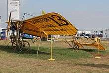
Wire wheels are used on most bicycles and are still used on many motorcycles. They were invented by aeronautical engineer George Cayley in 1808.[4] Although Cayley first proposed wire wheels, he did not apply for a patent. The first patent for wire wheels was issued to Theodore Jones of London, England on October 11, 1826.[5] Eugène Meyer of Paris, France was the first person to receive, in 1869, a patent for wire wheels on bicycles.[6]
Bicycle wheels were not strong enough for cars until the development of tangentially spoked wheels. They rapidly became well established in the bicycle and motor tricycle world but were not common on cars until around 1907. This was encouraged by the Rudge-Whitworth patented detachable and interchangeable wheels designed by John Pugh. These wheels owed their resistance to braking and accelerative stresses to their two inner rows of tangential spokes. An outer row of radial spokes gave lateral strength against cornering strains. These wheels were deeply dished so that steering pivot pins might lie as near as possible to the center-line of the tires. Their second feature was that they were easily detachable being mounted on splined false hubs. A process of assembling wire wheels is described as wheelbuilding.
On automobiles
After their artillery wheels proved inadequate US manufacturers paid John Pugh of Rudge-Whitworth royalties to manufacture wire wheels using his patents. This continued until the development of pressed steel wheels by Joseph Sankey which replaced wire wheels wherever the premium price of wire wheels was not justified by their weight saving.
- A sample of US-made cars first riding on wire wheels
-
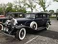
Cadillac
-

Chrysler
-
.JPG)
Ford
-

Lincoln
-
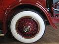
Packard
-
_(cropped).jpg)
Rolls-Royce Phantom III 1937 high-quality centre-lock (wire) wheels streamlined by nave plates
Sports cars
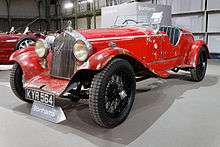
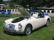
Before 1960, sports/racing cars usually had Rudge-Whitworth wire wheels center-locking equipped with splined hubs and a quick-release "knockoff" (central wing nut) locking cap[note 1] that could be unscrewed by striking a wing of the nut with a special alloy mallet or "knockoff hammer".[7] Some jurisdictions, including West Germany, prohibited eared hubcaps. Some manufacturers (e.g. Maserati) preferred to hold the wheel on the splined hub by capping with a single conventional unwinged nut requiring a special large spanner.
In the 1960s even lighter cast alloy wheels became usual—at first with splined hubs and knock-off caps—and now predominate. New versions of wire wheels are still made but often with standard hub bolt patterns covered by a center cap to fit without adapters.
-
.jpg)
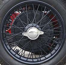
Ferrari knock-on wire-spoked wheel
by Italian manufacturer Ruote Borrani, in Milan

On motorcycles
At one time, motorcycles used wire wheels built up from separate components, but, except for dirtbikes, they are now used mainly for their retro appearance.
-
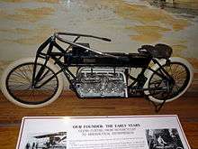
Wire wheels on a 1906 Curtiss V-8 motorcycle
-
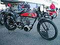
Wire wheels on a French San Sou Pap motorcycle
-

Wire wheels on a modern motocross-style motorcycle
-
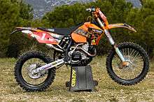
Wire wheels on a modern enduro-style motorcycle
-
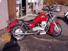
Wire wheels on a modern cruiser-style motorcycle
-
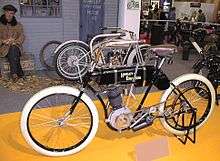
Wire wheels on the first Harley-Davidson motorcycle
On bicycles
The first commercially successful use of wired wheels was on bicycles. They were introduced early on in the development of the bicycle, following soon after the adoption of solid rubber tires. This development marked a major improvement over the older wooden wheels, both in terms of weight and comfort (the increased elasticity of the wheel helping to absorb road vibrations).[8]
In England, the engineer William Stanley developed the steel-wired spider wheel in 1849, an improvement over the cumbersome wooden spoked wheels then fitted to the tricycles that his employer was making.[9][10][11]
Bicycle manufacturers build millions of wheels annually, using the common crossed-spoke patterns whose crossings of adjacent spokes are governed by the number of spokes in the wheel. Wheelbuilders of racing teams and in good bicycle shops build wheels to other patterns such as two-cross, one-cross, or no-cross (usually called radial). Many of these patterns have been used for more than 100 years, it is claimed that crossed patterns have more strength and stability while irregular patterns are art forms and have little structural merit. [12]
In the 1980s, cast wheels with 5 or 6 rigid spokes began to appear in the Olympic Games and professional racing: these have advantages in specialized applications, such as time trials, but wire-spoked wheels are used for most purposes.
Reaction to load
The reaction to a radial load of a well-tensioned wire spoked wheel, such as by a rider sitting on a bicycle, is that the wheel flattens slightly near the ground contact area. The rest of the wheel remains approximately circular.[13][14][15][16] The tension of all the spokes does not increase significantly. Instead, only the spokes directly under the hub decrease their tension.[12][17][18][19] The issue of how best to describe this situation is debated.[20] Some authors conclude from this that the hub "stands" on those spokes immediately below it that experience a reduction in tension, even though the spokes below the hub exert no upward force on the hub and can be replaced by chains without much changing the physics of the wheel.[15][12] Other authors conclude that the hub "hangs" from those spokes above it that exert an upward force on the hub, and that have higher tension than the spokes below the hub, which pull down on the hub.[18][21]
Despite being composed of thin and relatively flexible spokes, wire wheels are radially stiff and provide very little suspension compliance compared to even high-pressure bicycle tires.[22][23][24][25]
Gallery
-
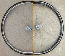
Bicycle wheels with a radial spoke pattern (left) and three cross (right)
-
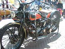
Early Harley-Davidson with wire wheels
-
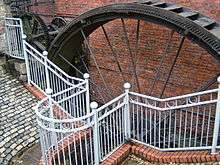
A suspension wheel at the Portland Basin Canal Warehouse
Note
- ↑ 1.3.4 Wire wheels
The center-lock wire wheel is traditionally associated with vintage sports cars and racing cars, and for those of us of advancing years the blood is still stirred by memories of split-seconds saved by the deft application of copper-headed hammers to eared hubcaps. We also remember . . .
page 5, Colin Campbell New Directions in Suspension Design: Making the Fast Car Faster Taylor & Francis, 1981, USA. ISBN 0-8376-0150-9.
References
- ↑ Forester, John (August 1980). "Held Up By Downward Pull". American Wheelmen. Retrieved 2012-06-26.
how the tension spoked wheel carries its load
- ↑ Brown, Sheldon. "Bicycle Tires and Tubes, How a Tire Supports its Load". Retrieved 2012-06-26.
The tension-spoked wheel and the pneumatic tire are two examples of what are called preloaded tensile structures, brilliant, counterintuitive designs working together remarkably to support as much as 100 times their own weight.
- 1 2 C. S. Walker (1920). "Wire Wheels". Society of Automotive Engineers. pp. 425–432. Retrieved 2012-06-26.
As the wire wheel is a "suspension" wheel, the car weight is hung or "cradled" from scores of resilient, flexible spokes.
- ↑ In his notebook, dated March 19, 1808, Cayley proposed that in order to produce "the lightest possible wheel for aerial navigation cars," one should "do away with wooden spokes altogether and refer the whole firmness of the wheel to the strength of the rim only, by the intervention of tight strong cording … " See: J.A.D. Ackroyd (2011) "Sir George Cayley: The invention of the aeroplane near Scarborough at the time of Trafalgar," Journal of Aeronautical History [Internet publication], paper no. 6, pages 130-181. Cayley's tension-spoke wheel appears on page 152, "3.7 The Tension Wheel, 1808".
- ↑ See:
- Notice of Theodore Jones' patent for wire wheels: Repertory of patent inventions, etc., no. 17 (November 1826), page 320.
- Illustrations and description of Jones' wire wheel: Luke Hebert, ed. (April 20, 1828) "Patent suspension wheels," The Register of Arts, and Journal of Patent Inventions, 2nd series, 2 (29) : pages 65-66.
- ↑ Bulletin des lois de la République française (1873) 12th series, vol. 6, page 648, patent no. 86,705: "Perfectionnements dans les roues de vélocipèdes" (Improvements in the wheels of bicycles), issued: 4 August 1869.
- ↑ Wilson McComb. "Principles of the Centre-Lock Wire Wheel". Retrieved 2013-05-18.
Let us take a closer look at this assembly, referring to the central portion of the wheel as the "wheel center", which is fitted to the "hub" and fixed in place with a 'locking cap'.
- ↑ Herlihy, David V (2004). Bicycle: the History. Yale University Press. pp. 141–142. ISBN 0-300-10418-9.
- ↑ McConnell, Anita (2004). "Stanley, William Ford Robinson (1829–1909)". Oxford Dictionary of National Biography (subscription required - free to holders of tickets for British libraries). Oxford University Press. Retrieved 9 September 2009.
- ↑ Owen, W.B. (1912). Sir Sidney Lee, ed. Dictionary of National Biography - William Ford Robinson Stanley. Second Supplement. III (Neil-Young). London: Smith, Elder & Co. pp. 393–394.
- ↑ "Good week to go for ride". The Croydon Guardian. 10 June 2006. Retrieved 9 September 2009.
- 1 2 3 Brandt, Jobst (1981). The Bicycle Wheel. Avocet. pp. 12–20. ISBN 0-9607236-2-5.
- ↑ Forester, John (August 1980). "Held Up By Downward Pull". American Wheelmen.
- ↑ Whitt, Frank R.; David G. Wilson (1982). Bicycling Science (Second ed.). Massachusetts Institute of Technology. pp. 106–138. ISBN 0-262-23111-5.
- 1 2 Ian Smith. "Bicycle Wheel Analysis". Retrieved 2008-12-31.
I conclude that it is perfectly reasonable to say that the hub stands on the lower spokes, and that it does not hang from the upper spokes.
- ↑ C.J. Burgoyne and R. Dilmaghanian (March 1993). "Bicycle Wheel as Prestressed Structure" (pdf). Journal of Engineering Mechanics. 119 (3): 439–455. doi:10.1061/(asce)0733-9399(1993)119:3(439). ISSN 0733-9399.
Only the spokes in contact with the ground, or near the ground, show significant strains.
- ↑ Wilson, David Gordon; Jim Papadopoulos (2004). Bicycling Science (Third ed.). Massachusetts Institute of Technology. pp. 389–390. ISBN 0-262-73154-1.
- 1 2 Tom Fine (September 1998). "Hubs hang from the rim!". Retrieved 2010-03-16.
I still say, without any doubt, that the hub hangs from the upper spokes.
- ↑ Henri P. Gavin (August 1996). "Bicycle Wheel Spoke Patterns and Spoke Fatigue" (pdf). ASCE Journal of Engineering Mechanics. 122 (8): 736–742. doi:10.1061/(ASCE)0733-9399(1996)122:8(736).
- ↑ Kraig Willett (5 September 2004). "Hang or Stand?". BikeTech Review. Retrieved 2010-03-16.
A little known semantic debate ... has been raging on the usenet newsgroups for quite some time. The point of contention in this debate is whether or not a loaded bicycle wheel "stands" on the bottom spokes or "hangs" from the top ones?
- ↑ Samuel K. Clark, V. E. Gough (1981). Mechanics of Pneumatic Tires. U.S. Department of Transportation. p. 241.
The system of load transmission is analogous to that of a cycle wheel where the hub hangs by the steel wire spokes from the top of the rim, which is loaded at the bottom.
- ↑ John Swanson (2006). "Performance of the Bicycle Wheel, A Method for Analysis" (PDF). BikePhysics.com. Retrieved 2012-06-25.
Radial Stiffness: There's almost -no- vertical compliance in your wheel and people who insist that they can feel the vertical stiffness or “harshness” of a wheel are mistaken. The radial stiffness of a bicycle wheel is ~ 3-4000 N/mm. This equals a deflection of 0.1 mm under a 40 kg load. Sorry princess, but that gets obscured by the amount of deflection in the tires, fork, saddle, handlebar tape, frame, and even your gloves.
- ↑ Henri P. Gavin (1996). "Bicycle Wheel Spoke Patterns and Spoke Fatigue" (PDF). ASCE Journal of Engineering Mechanics. Retrieved 2012-06-25.
radial wheel stiffness (N/mm): 2500-5000
- ↑ Ian (2002). "Spoke Patterns". astounding.org.uk. Retrieved 2012-06-25.
A radially spoked wheel is about 4.6% stiffer than a tangentially spoked one. Alternatively, if you apply 1000N (about 100kg, 220lb) to each of the wheels, the tangential (four-cross) spoked one deflects 0.0075mm (0.0003 inch) more than the radial spoked. Since the tyre is likely to deflect several millimetres at least (if 3mm, that's 400 times more deflection) I conclude the spoking is unlikely to make a discernible difference to the vertical stiffness of the wheel.
- ↑ Jobst Brandt (1981). "Sheldon Brown's Bicycle Glossary: Radial spoking". Sheldon Brown (bicycle mechanic). Retrieved 2012-06-25.
There is no change in radial elasticity between a radial and crossed spoke wheel with the same components, other than the length of the spokes. A 290 mm spoke is 3% stiffer than a 300 mm spoke of the same type. Since spokes stretch elastically about 0.1mm on a hard bump (not ordinary road ripples), the elastic difference between the radial and cross-three wheel is 3% x 0.1mm = 0.003 mm. Copier paper is 0.075 mm thick, and if you can feel that when you ride over it on a glassy smooth concrete surface, please let me know. You have greater sensitivity than the lady in "the princess and the pea" fable.
External links
| Wikimedia Commons has media related to Wire Wheels. |
- Astounding.org.uk, an analysis of the deflection of wire wheels.
- Duke.edu, an analysis of the deflection of wire wheels (PDF format).