Apple Desktop Bus
|
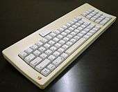
The ADB Icon and an early ADB keyboard. | |||
| Type | Human input device interface | ||
|---|---|---|---|
| Production history | |||
| Designer | Steve Wozniak/Apple Computer | ||
| Designed | 1986 | ||
| Manufacturer | Apple Computer Inc. | ||
| Produced | 1986 to 1999 | ||
| Superseded | RS-422/6522 keyboard and mouse | ||
| Superseded by | USB and FireWire (1998-1999) | ||
| General specifications | |||
| Hot pluggable | occasional support | ||
| External | yes | ||
| Pins | 4 | ||
| Connector | Mini-DIN | ||
| Data | |||
| Data signal | Bi-directional serial command stream | ||
| Bitrate |
125 kbit/s maximum (~10 kbit/s actual) | ||
| Max. devices |
16 maximum (~5 actual, 3 supported) | ||
| Protocol | Serial | ||
| Pin out | |||
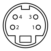 | |||
| Female socket from the front. | |||
| Pin 1 | ADB | Data | |
| Pin 2 | PSW | Power on | |
| Pin 3 | +5 V | +5 volts power | |
| Pin 4 | GND | Ground | |
| Same connector as S-Video | |||
Apple Desktop Bus (ADB) is a bit-serial peripheral bus connecting low-speed devices to computers. It was introduced on the Apple IIGS in 1986 as a way to support low-cost devices like keyboards and mice, allowing them to be connected together in a daisy chain without the need for hubs or other devices. ADB was quickly introduced on later Macintosh models, on later models of NeXT computers, and saw some other 3rd party use as well. Like the similar PS/2 connector used in many PC-compatibles at the time, ADB was rapidly replaced by USB as that system became popular in the late 1990s; the last external ADB port on an Apple product was in 1999, though it remained as an internal-only bus on some Mac models into the 2000s.
History
AppleBus
Early during the creation of the Macintosh computer, the engineering team had selected the fairly sophisticated Zilog 8530 to supply serial communications. This was initially done to allow multiple devices to be plugged into a single port, using simple networking protocols implemented inside the 8530 to allow them to send and receive data with the host computer. The original design, known as AppleBus, had many of the same features as USB in terms of performance and device support.
During development of the AppleBus system, computer networking became a vitally important feature of any computer system. With no card slots, the Macintosh was unable to easily add support for Ethernet or similar local area networking standards. Work on AppleBus was re-directed to networking purposes, and was released in 1985 as the AppleTalk system. This left the Mac with the original single-purpose mouse and keyboard ports, and no general purpose system for low-speed devices to use.
ADB
ADB was created by Steve Wozniak, who had been looking for a project to work on in the mid-1980s. Someone suggested that he should create a new connection system for devices like mice and keyboards, one that would require only a single daisy-chained cable, and be inexpensive to implement. As the story goes, he went away for a month and came back with ADB.
The first system to use ADB was the Apple IIGS in 1986. It was subsequently used on all Apple Macintosh machines starting with the Macintosh II and Macintosh SE. ADB was also used on later models of NeXT computers.[1] The vast majority of ADB devices were for input, including track balls, joysticks, graphics tablets and similar devices. Special-purpose uses included software protection dongles and even the Teleport modem.
Move to USB
The first Macintosh to move from ADB was the iMac in 1998, which featured USB in its place. The last Apple computer to have an ADB port was the "Yosemite" Power Macintosh G3 in 1999. No machines being built today use ADB for device interconnection, but up to February 2005, PowerBooks and iBooks still used the ADB protocol in the internal interface with the built-in keyboard and touchpad. Subsequent models used a USB-based trackpad.
Design
Physical
In keeping with Apple's general philosophy of industrial design, ADB was intended to be as simple to use as possible, while still being inexpensive to implement. A suitable connector was found in the form of the 4 pin mini-DIN connector, which is also used for S-Video. The connectors were small, widely available, and can only be inserted the "correct way". They do not lock into position, but even with a friction fit they are firm enough for light duties like those intended for ADB. ADB can be implemented for less than a penny; the connector always costs more than the controller hardware.
ADB's protocol required only a single pin for data, labeled ADB. Two of the other pins were used for +5 V power supply and ground. The +5 V pin guaranteed at least 500 mA, and required devices to use only 100 mA each. ADB also included the PSW pin which was attached directly to the power supply of the host computer. This was included to allow a key on the keyboard to start up the machine without needing the ADB software to interpret the signal. In more modern designs an auxiliary microcontroller is always kept running, so it is economical to use a power-up command over the standard USB channel.
Most serial digital interfaces use a separate clock pin to signal the arrival of individual bits of data. However, Wozniak decided that a separate wire for a clock signal was not necessary; and as ADB was designed to be low-cost, it made economical sense to leave it out. Like modems, the system locked onto the signal rise and fall times to recreate a clock signal.
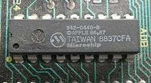
The decoding transceiver ASIC was available only by request, as Apple preferred to work more closely with vendors. Apple possibly sold this hardware below cost to encourage peripheral development and their own economy of scale. In the Macintosh SE, the ADB is implemented in an Apple branded Microchip PIC16CR54 Microcontroller.
Communication
The ADB system is based around the devices having the ability to decode a single number (the address) and being able to hold several small bits of data (their registers). All traffic on the bus is driven by the host computer, which sends out commands to read or write data: devices are not allowed to use the bus unless the computer first requests it.
These requests took the form of single-byte strings. The upper four bits contained the address, the ID of one of the devices on the chain. The four bits allowed for up to 16 devices on a single bus. The next two bits specified one of four commands, and the final two bits indicated one of four registers. The commands were:
-
talk- send the contents of a register to the computer -
listen- set the register to the following number -
flush- clear the contents of the register -
reset- tell everyone on the bus to reset
For instance, if the mouse was known to be at address $D, the computer would periodically send out a message on the bus that looked something like...
1101 11 00
This says that device $D (1101) should talk (11) and return the contents of register zero (00). To a mouse this means "tell me the latest position changes". Registers could contain between two and eight bytes. Register zero was generally the primary communications channel. Registers one and two were undefined, and were generally intended to allow 3rd party developers to store configuration information. Register three always contained device identification information.
Enumeration and identification
The addresses and enumeration of the devices were set to default values when reset. For instance, all keyboards were set to $2, and all mice to $3. When the machine was first powered on the ADB device driver would send out talk commands asking each of these known default address, in turn, for the contents of register three. If no response came from a particular address, the computer marked it dead and didn't bother polling it later.
If a device did respond, it did so by saying it was moving to a new randomly selected higher address. The computer then responded by sending another command to that new address, asking the device to move to yet another new address. Once this completed that device was marked live, and the system continued polling it in the future. Once all of the devices were enumerated in this fashion the bus was ready to be used.
Although it was not common, it was possible for the ADB bus to have more than one device of the same sort plugged in — two graphics tablets or software copy protection dongles for instance. In this case when it asked for devices on that default address, both would respond and a collision could occur. The devices included a small bit of timing that allowed them to avoid this problem. After receiving a message from the host, the devices waited a short random time before responding, and then only did so after "snooping" the bus to make sure it was not busy.
With two dongles plugged in, for instance, when the bus was first setting up and queried that address, one of them would be the first to respond due to the random wait timer. The other would notice the bus was busy and not respond. The host would then send out another message to that original address, but since one device had moved to a new address, only the other would then respond. This process continued until no one responded to the request on the original address, meaning there were no more devices of that type to enumerate.
Data rates on the bus were theoretically as high as 125 kbit/s. However, the actual speed was at best half that due to there being only one pin being shared between the computer and devices, and in practice throughput was even less as the entire system was driven by how fast the computer polled the bus. The classic Mac OS was not particularly well suited to this task, and the bus often got bogged down at about 10 kbit/s. Early Teleport modems running at 2400 bit/s had no problems using ADB, but later models were forced to move to the more expensive RS422 ports as speeds moved to 14.4 kbit/s and higher.
Problems
One peculiarity of ADB was that in spite of being electrically unsafe for hot-swapping on all but a few machines, it had all of the basic capabilities needed for hot-swapping implemented in its software and support hardware. On practically all original ADB systems it is not safe to plug in or unplug a device once the system is powered on (unlike modern day busses designed with hot-swap in mind). This could cause the opening of a soldered-in fuse on the motherboard. If brought to an authorised dealer this could result in a motherboard swap at a significant expense. A simple alternative was to obtain a fuse at a nominal cost and wire it in parallel across the open motherboard fuse (not even requiring soldering if done appropriately).
The mini-DIN connector was only rated for 400 insertions and it was easy to bend a pin if not inserted with caution; in addition, the socket could become loose, resulting in intermittent function.
Presaging the disappearance of the second port on newer FireWire devices, some ADB devices lacked a pass-through connector, making it impossible to daisy-chain more than one such device at a time without obscure splitter units. Keyboards, software dongles, graphics tablets, game pads and joysticks typically had pass-through connectors, while few mice or trackballs had them.
While Mini-DIN connectors cannot be plugged in the "wrong way", it is possible to have trouble finding the right way without looking inside the circular connector's shroud. Apple attempted to help by using U-shaped soft plastic grips around the connectors to key both plugs and sockets so the flat side has a specific relation to the shell keyway, but this feature was ignored by some 3rd-party manufacturers. Additionally, there are four ways to orient the receiving socket on a device such as a keyboard; various Apple keyboards have used at least three of these possible orientations.
Patents
- 4,875,158 Ashkin; Peter B. (Los Gatos, CA), Clark; Michael (Glendale, CA)
- 4,910,655 Ashkin; Peter B. (Los Gatos, CA), Clark; Michael (Glendale, CA)
- 4,912,627 Ashkin; Peter B. (Los Gatos, CA), Clark; Michael (Glendale, CA)
- 4,918,598 Ashkin; Peter B. (Los Gatos, CA), Clark; Michael (Glendale, CA)
- 5,128,677 Donovan; Paul M. (Santa Clara, CA), Caruso; Michael P. (Sudbury, MA)
- 5,175,750 Donovan; Paul M. (Santa Clara, CA), Caruso; Michael P. (Sudbury, MA)
- 5,828,857 Scalise; Albert M. (San Jose, CA)
See also
References
External links
- About the ADB Manager
- Apple Documentation on the ADB Protocol
- Apple doc on the ADB port
- Complete hardware specification of ADB devices and protocol (Apple Guide to the Macintosh Family Hardware)
- Microchip Application note on ADB device development
| General | |
|---|---|
| Standards |
|
| Storage | |
| Peripheral | |
| Audio | |
| Portable | |
| Embedded | |
Interfaces are listed by their speed in the (roughly) ascending order, so the interface at the end of each section should be the fastest. | |
| Products and projects | 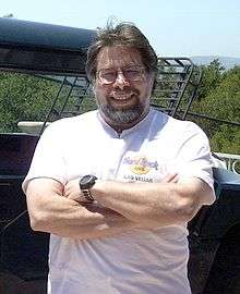 | |
|---|---|---|
| Companies |
| |
| Awards |
| |
| Film | ||
| TV appearances | ||
| Related | ||