Audio crossover
Audio crossovers are a class of electronic filter used in audio applications. Most individual loudspeaker drivers are incapable of covering the entire audio spectrum from low frequencies to high frequencies with acceptable relative volume and absence of distortion so most hi-fi speaker systems use a combination of multiple loudspeaker drivers, each catering to a different frequency band. Crossovers split the audio signal into separate frequency bands that can be separately routed to loudspeakers optimized for those bands.
Active crossovers are distinguished from passive crossovers in that they divide the audio signal prior to amplification. Active crossovers come in both digital and analog varieties. Digital active crossovers often include additional signal processing, such as limiting, delay, and equalization.
Signal crossovers allow the audio signal to be split into bands that are processed separately before they are mixed together again. Some examples are: multiband dynamics (compression, limiting, de-essing), multiband distortion, bass enhancement, high frequency exciters, and noise reduction such as Dolby A noise reduction.
Overview
The definition of an ideal audio crossover changes relative to the task at hand. If the separate bands are to be mixed back together again (as in multiband processing), then the ideal audio crossover would split the incoming audio signal into separate bands that do not overlap or interact and which result in an output signal unchanged in frequency, relative levels, and phase response. This ideal performance can only be approximated. How to implement the best approximation is a matter of lively debate. On the other hand, if the audio crossover separates the audio bands in a loudspeaker, there is no requirement for mathematically ideal characteristics within the crossover itself, as the frequency and phase response of the loudspeaker drivers within their mountings will eclipse the results. Satisfactory output of the complete system comprising the audio crossover and the loudspeaker drivers in their enclosure(s) is the design goal. Such a goal is often achieved using non-ideal, asymmetric crossover filter characteristics.[1]
Many different crossover types are used in audio, but they generally belong to one of the following classes.
Classification
Classification based on the number of filter sections
Loudspeakers are often classified as "N-way", where N is the number of drivers in the system. For instance, a speaker with a woofer and a tweeter is 2-way. An N-way speaker usually has an N-way crossover to divide the signal among the drivers. A 2-way crossover consists of a low-pass and a high-pass filter. A 3-way crossover is constructed as a combination of low-pass, band-pass and high-pass filters (LPF, BPF and HPF respectively). The BPF section is in turn a combination of HPF and LPF sections. 4 (or more) way crossovers are not very common in speaker design, primarily due to the complexity involved, which is not generally justified by better acoustic performance.
An extra HPF section may be present in an "N-way" loudspeaker crossover to protect the lowest-frequency driver from frequencies lower than it can safely handle. Such a crossover would then have a bandpass filter for the lowest-frequency driver. Similarly, the highest-frequency driver may have a protective LPF section to prevent high frequency damage, though this is far less common.
Recently, a number of manufacturers have begun using what is often called "N.5-way" crossover techniques for stereo loudspeaker crossovers. This usually indicates the addition of a second woofer that plays the same bass range as the main woofer but rolls off far before the main woofer does.
Remark: Filter sections mentioned here is not to be confused with the individual 2-pole filter sections that a higher order filter consists of.
Classification based on components
Crossovers can also be classified based on the type of components used.
Passive

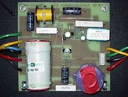
A passive crossover is made entirely of passive components, arranged most commonly in a Cauer topology to achieve a Butterworth filter. Passive filters use resistors combined with reactive components such as capacitors and inductors. Very high performance passive crossovers are likely to be more expensive than active crossovers since individual components capable of good performance at the high currents and voltages at which speaker systems are driven are hard to make. Polypropylene, metalized polyester foil, paper and electrolytic capacitors are common. Inductors may have air cores, powdered metal cores, ferrite cores, or laminated silicon steel cores, and most are wound with enamelled copper wire. Some passive networks include devices such as fuses, PTC devices, bulbs or circuit breakers to protect the loudspeaker drivers from accidental overpowering. Modern passive crossovers increasingly incorporate equalization networks (e.g., Zobel networks) that compensate for the changes in impedance with frequency inherent in virtually all loudspeakers. The issue is complex, as part of the change in impedance is due to acoustic loading changes across a driver's passband.
On the negative side, passive networks may be bulky and cause power loss. They are not only frequency specific, but also impedance specific. This prevents interchangeability with speaker systems of different impedances. Ideal crossover filters, including impedance compensation and equalization networks, can be very difficult to design, as the components interact in complex ways. Crossover design expert Siegfried Linkwitz said of them that "the only excuse for passive crossovers is their low cost. Their behavior changes with the signal level dependent dynamics of the drivers. They block the power amplifier from taking maximum control over the voice coil motion. They are a waste of time, if accuracy of reproduction is the goal."[2]
Alternatively, passive components can be utilised to construct filter circuits before the amplifier. This is called passive line-level crossover.
Active
An active crossover contains active components in its filters. In recent years, the most commonly used active device is an op-amp; active crossovers are operated at levels suited to power amplifier inputs in contrast to passive crossovers which operate after the power amplifier's output, at high current and in some cases high voltage. On the other hand, all circuits with gain introduce noise, and such noise has a deleterious effect when introduced prior to the signal being amplified by the power amplifiers.
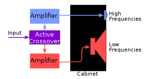
Active crossovers always require the use of power amplifiers for each output band. Thus a 2-way active crossover needs two amplifiers—one each for the woofer and tweeter. This means that an active crossover based system will often cost more than a passive crossover based system. Despite the cost and complication disadvantages, active crossovers provide the following advantages over passive ones:
- a frequency response independent of the dynamic changes in a driver's electrical characteristics.
- typically, the possibility of an easy way to vary or fine tune each frequency band to the specific drivers used. Examples would be crossover slope, filter type (e.g., Bessel, Butterworth, etc.), relative levels, ...
- better isolation of each driver from signals handled by other drivers, thus reducing intermodulation distortion and overdriving
- The power amplifiers are directly connected to the speaker drivers, thereby maximizing amplifier damping control of the speaker voice coil, reducing consequences of dynamic changes in driver electrical characteristics, all of which are likely to improve the transient response of the system
- reduction in power amplifier output requirement. With no energy being lost in passive components, amplifier requirements are reduced considerably (up to 1/2 in some cases), reducing costs, and potentially increasing quality.
Digital
Active crossovers can be implemented digitally using a DSP chip or other microprocessor. They either use digital approximations to traditional analog circuits, known as IIR filters (Bessel, Butterworth, Linkwitz-Riley etc.), or they use Finite impulse response (FIR) filters. IIR filters have many similarities with analog filters and are relatively undemanding of CPU resources; FIR filters on the other hand usually have a higher order and therefore require more resources for similar characteristics. They can be designed and built so that they have a linear phase response, which is thought desirable by many involved in sound reproduction. There are drawbacks though—in order to achieve linear phase response, a longer delay time is incurred than would be necessary with an IIR or minimum phase FIR filters. IIR filters, which are by nature recursive have the drawback that if not carefully designed they may enter limit cycles resulting in non-linear distortion.
Mechanical
This crossover type is mechanical and uses the properties of the materials in a driver diaphragm to achieve the necessary filtering. Such crossovers are commonly found in full-range speakers which are designed to cover as much of the audio band as possible. One such is constructed by coupling the cone of the speaker to the voice coil bobbin through a compliant section and directly attaching a small lightweight whizzer cone to the bobbin. This compliant section serves as a compliant filter, so the main cone is not vibrated at higher frequencies. The whizzer cone responds to all frequencies, but due to its smaller size only gives a useful output at higher frequencies, thereby implementing a mechanical crossover function. Careful selection of materials used for the cone, whizzer and suspension elements determines the crossover frequency and the effectiveness of the crossover. Such mechanical crossovers are complex to design, especially if high fidelity is desired. Computer aided design has largely replaced the laborious trial and error approach that was historically used. Over several years, the compliance of the materials may change, negatively affecting the frequency response of the speaker.
A more common approach is to employ the dust cap as a high frequency radiator. The dust cap radiates low frequencies, moving as part of the main assembly, but due to low-mass and reduced damping, radiates increased energy at higher frequencies. As with whizzer cones, careful selection of material, shape and position are required to provide smooth, extended output. High frequency dispersion is somewhat different for this approach than for whizzer cones. A related approach is to shape the main cone with such profile, and of such materials, that the neck area remains more rigid, radiating all frequencies, while the outer areas of the cone are selectively decoupled, radiating only at lower frequencies. Cone profiles and materials can be modeled in FEA software and the results predicted to excellent tolerances.
Speakers which use these mechanical crossovers have some advantages in sound quality despite the difficulties of designing and manufacturing them, and despite the inevitable output limitations. Full-range drivers have a single acoustic center, and can have relatively modest phase change across the audio spectrum. For best performance at low frequencies, these drivers require careful enclosure design. Their small size (typically 165 to 200 mm) requires considerable cone excursion to reproduce bass effectively, but the short voice coils required for reasonable high frequency performance can only move over a limited range. Nevertheless, within these constraints, cost and complications are reduced, as no crossovers are required.
Classification based on filter order or slope
Just as filters have different orders, so do crossovers, depending on the filter slope they implement. The final acoustic slope may be completely determined by the electrical filter or may be achieved by combining the electrical filter's slope with the natural characteristics of the driver. In the former case, the only requirement is that each driver has a flat response at least to the point where its signal is approximately −10dB down from the passband. In the latter case, the final acoustic slope is usually steeper than that of the electrical filters used. A third- or fourth-order acoustic crossover often has just a second order electrical filter. This requires that speaker drivers be well behaved a considerable way from the nominal crossover frequency, and further that the high frequency driver be able to survive a considerable input in a frequency range below its crossover point. This is difficult in actual practice. In the discussion below, the characteristics of the electrical filter order is discussed, followed by a discussion of crossovers having that acoustic slope and their advantages or disadvantages.
Most audio crossovers use first to fourth order electrical filters. Higher orders are not generally implemented in passive crossovers for loudspeakers, but are sometimes found in electronic equipment under circumstances for which their considerable cost and complexity can be justified.
First order
First-order filters have a 20 dB/decade (or 6 dB/octave) slope. All first-order filters have a Butterworth filter characteristic. First-order filters are considered by many audiophiles to be ideal for crossovers. This is because this filter type is 'transient perfect', meaning it passes both amplitude and phase unchanged across the range of interest. It also uses the fewest parts and has the lowest insertion loss (if passive). A first-order crossover allows more signals of unwanted frequencies to get through in the LPF and HPF sections than do higher order configurations. While woofers can easily take this (aside from generating distortion at frequencies above those they can properly handle), smaller high frequency drivers (especially tweeters) are more likely to be damaged since they are not capable of handling large power inputs at frequencies below their rated crossover point.
In practice, speaker systems with true first order acoustic slopes are difficult to design because they require large overlapping driver bandwidth, and the shallow slopes mean that non-coincident drivers interfere over a wide frequency range and cause large response shifts off-axis.
Second order
Second-order filters have a 40 dB/decade (or 12 dB/octave) slope. Second-order filters can have a Bessel, Linkwitz-Riley or Butterworth characteristic depending on design choices and the components used. This order is commonly used in passive crossovers as it offers a reasonable balance between complexity, response, and higher frequency driver protection. When designed with time aligned physical placement, these crossovers have a symmetrical polar response, as do all even order crossovers.
It is commonly thought that there will always be a phase difference of 180° between the outputs of a (second order) low-pass filter and a high-pass filter having the same crossover frequency. And so, in a 2-way system, the high-pass section's output is usually connected to the high frequency driver 'inverted', to correct for this phase problem. For passive systems, the tweeter is wired with opposite polarity to the woofer; for active crossovers the high-pass filter's output is inverted. In 3-way systems the mid-range driver or filter is inverted. However, this is generally only true when the speakers have a wide response overlap and the acoustic centers are physically aligned.
Third order
Third-order filters have a 60 dB/decade (or 18 dB/octave) slope. These crossovers usually have Butterworth filter characteristics; phase response is very good, the level sum being flat and in phase quadrature, similar to a first order crossover. The polar response is asymmetric. In the original D'Appolito MTM arrangement, a symmetrical arrangement of drivers is used to create a symmetrical off-axis response when using third-order crossovers.
Third-order acoustic crossovers are often built from first- or second-order filter circuits.
Fourth order

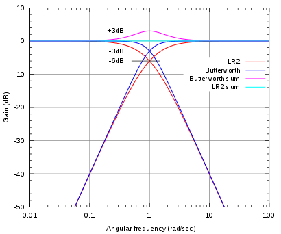
Fourth-order filters have an 80 dB/decade (or 24 dB/octave) slope. These filters are complex to design in passive form, because the components interact with each other. Steep-slope passive networks are less tolerant of parts value deviations or tolerances, and more sensitive to mis-termination with reactive driver loads. A 4th order crossover with −6 dB crossover point and flat summing is also known as a Linkwitz-Riley crossover (named after its inventors), and can be constructed in active form by cascading two 2nd order Butterworth filter sections. The output signals of this crossover order are in phase, thus avoiding partial phase inversion if the crossover bandpasses are electrically summed, as they would be within the output stage of a multiband compressor. Crossovers used in loudspeaker design do not require the filter sections to be in phase: smooth output characteristics are often achieved using non-ideal, asymmetric crossover filter characteristics.[1] Bessel, Butterworth and Chebyshev are among the possible crossover topologies.
Such steep-slope filters have greater problems with overshoot and ringing[3] but there are several key advantages, even in their passive form, such as the potential for a lower crossover point and increased power handling for tweeters, together with less overlap between drivers, dramatically reducing lobing, or other unwelcome off-axis effects. With less overlap between adjacent drivers, their location relative to each other becomes less critical and allows more latitude in speaker system cosmetics or (in car audio) practical installation constraints.
Higher order
Passive crossovers giving acoustic slopes higher than fourth-order are not common because of cost and complexity. Filters of up to 96 dB per octave are available in active crossovers and loudspeaker management systems.
Mixed order
Crossovers can also be constructed with mixed order filters. For example, a second order lowpass combined with a third order highpass. These are generally passive and are used for several reasons, often when the component values are found by computer program optimization. A higher order tweeter crossover can sometimes help compensate for the time offset between the woofer and tweeter, caused by non aligned acoustic centers.
Classification based on circuit topology
Parallel
Parallel crossovers are by far the most common. Electrically the filters are in parallel and thus the various filter sections do not interact. This makes two-way crossovers easier to design because the sections can be considered separately, and because component tolerance variations will be isolated. Parallel crossovers also have the advantage of allowing the speaker drivers to be bi-wired. In the years before computer modeling, simplistic three-way crossovers were designed as a pair of two-way crossovers, but the advent of iterative design software has taught that this old technique creates excess gain and a 'haystack' response in the midrange output, together with a lower than anticipated input impedance.
Series
In this topology, the individual filters are connected in series, and a driver or driver combination is connected in parallel with each filter. To understand the signal path in this type of crossover, refer to the "Series Crossover" figure, and consider a high frequency signal that, during a certain moment, has a positive voltage on the upper Input terminal compared to the lower Input terminal. The low pass filter (LPF) presents a high impedance to the signal, and the tweeter presents a low impedance; so the signal passes through the tweeter. The signal continues to the connection point between the woofer and the high pass filter (HPF). There, the HPF presents a low impedance to the signal, so the signal passes through the HPF, and appears at the lower Input terminal. A low frequency signal with a similar instantaneous voltage characteristic first passes through the LPF, then the woofer, and appears at the lower Input terminal.
Derived
Derived crossovers include active crossovers in which one of the crossover responses is derived from the other through the use of a differential amplifier. For example, the difference between the input signal and the output of the high pass section is a low pass response.[4] Thus, when a differential amplifier is used to extract this difference, its output constitutes the low pass filter section. The main advantage of derived filters is that they produce no phase difference between the high pass and low pass sections at any frequency.[4] The disadvantages are either
- (a) that the high pass and low pass sections often have different levels of attenuation in their stop bands, i.e. their slopes are asymmetrical,[4] or
- (b) that the response of one or both sections peaks near the crossover frequency,[5]
or both. In case (a), above, the usual situation is that the derived low pass response attenuates at a much slower rate than the fixed response. This requires the speaker to which it is directed to continue to respond to signals deep into the stopband where its physical characteristics may not be ideal. In the case of (b), above, both speakers are required to operate at higher volume levels as the signal nears the crossover points. This uses more amplifier power and may drive the speaker cones into non-linearity.
See also
- Bass management
- Electrical characteristics of a dynamic loudspeaker
- Powered speakers
- Loudspeaker enclosure
- Full-range speaker
- Tweeter
- Super tweeter
- Midrange speaker
- Woofer
- Subwoofer
References
- 1 2 Hughes, Charles. "Using Crossovers in the Real World". Excelsior Audio Design and Services.
- ↑ Linkwitz, Siegfried (October 2009). "Crossovers". Retrieved March 31, 2010.
- ↑ Rane. RaneNote. Linkwitz-Riley Crossovers: A Primer. Retrieved December 7, 2008
- 1 2 3 Bohn, D. (Ed.), Audio Handbook (National Semiconductor Corporation, Santa Clara, CA 1976) § 5.2.4
- ↑ See, Crawford, D., Constructing a Room Equalizer, Audio Magazine, Sept. 1972 p. 21, in which the slopes are symmetrical, and The Audio Pages, Subtractive Crossover Networks. http://sound.westhost.com/articles/derived-xovers.htm Retrieved August 11, 2007.
External links
- Lenard Education on crossovers illustrated overview of audio crossovers.
- diyAudioAndVideo.com – DIY Audio site with information on building crossovers. Includes a crossover calculator for 15 different types of crossovers.
- KS Digital – makers of several loudspeakers with digital crossovers
- Article about active crossovers
- Comparison of active and passive crossovers
- Comparison of series and parallel crossovers
- Description of a L-R crossover
- Passive crossover design article
- Linkwitz Lab Crossovers
- Linkwitz-Riley Crossovers: A Primer
- Design of Digital Linear Phase FIR Crossover Systems
- Full-range Driver & Loudspeaker Theory
- Audioholics.com Filter & Crossover Types
- A Bessel Filter Crossover, and Its Relation to Others
- Active Lowpass Filter Design