Corium (nuclear reactor)
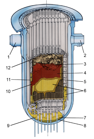
- Inlet 2B
- Inlet 1A
- Cavity
- Loose core debris
- Crust
- Previously molten material
- Lower plenum debris
- Possible region depleted in uranium
- Ablated incore instrument guide
- Hole in baffle plate
- Coating of previously-molten material on bypass region interior surfaces
- Upper grid damage
Corium, also called fuel containing material (FCM) or lava-like fuel containing material (LFCM), is a lava-like mixture of portions of a nuclear reactor core, formed during a nuclear meltdown, the most severe class of a nuclear reactor accident.
It consists of nuclear fuel, fission products, control rods, structural materials from the affected parts of the reactor, products of their chemical reaction with air, water and steam, and, in the event that the reactor vessel is breached, molten concrete from the floor of the reactor room.
Composition and formation
The heat causing the melting of a reactor may originate from the nuclear chain reaction, but more commonly decay heat of the fission products contained in the fuel rods is the primary heat source. The heat production from radioactive decay drops quickly, as the short half-life isotopes provide most of the heat and radioactive decay, with the curve of decay heat being a sum of the decay curves of numerous isotopes of elements decaying at different exponential half-life rates. A significant additional heat source can be the chemical reaction of hot metals with oxygen or steam.
Radioactive chain reaction and corresponding increased heat production may progress in parts of the corium if a critical mass occurs locally. This condition can be detected by presence of short life fission products long after the meltdown, in amounts that are too high to be from the controlled reaction inside the pre-meltdown reactor. Because nuclear chain reactions generate large amounts of heat and highly radioactive fission products, this condition is highly undesirable from a reactor vessel structure and biological safety perspective.[1]
The temperature of corium depends on its internal heat generation dynamics: the quantities and types of isotopes producing decay heat, dilution by other molten materials, heat losses modified by the corium physical configuration, and heat losses to the environment. A compact corium mass will lose less heat than a thinly spread layer. Corium of sufficient temperature can melt concrete. A solidified mass of corium can remelt if its heat losses drop, by being covered with heat insulating debris, or if water that is cooling the corium evaporates.[1]
Crust can form on the corium mass, acting as a thermal insulator and hindering thermal losses. Heat distribution throughout the corium mass is influenced by different thermal conductivity between the molten oxides and metals. Convection in the liquid phase significantly increases heat transfer.[1]
The molten reactor core releases volatile elements and compounds. These may be gas phase, such as molecular iodine or noble gases, or condensed aerosol particles after leaving the high temperature region. A high proportion of aerosol particles originate from the reactor control rod materials. The gaseous compounds may be adsorbed on the surface of the aerosol particles.
Corium composition and reactions
The composition of corium depends on the design type of the reactor, and specifically on the materials used in the control rods, coolant and reactor vessel structural materials. There are differences between pressurized water reactor (PWR) and boiling water reactor (BWR) coriums.
In contact with water, hot boron carbide from BWR reactor control rods forms first boron oxide and methane, then boric acid. Boron may also continue to contribute to reactions by the boric acid in an emergency coolant.
Zirconium from zircaloy, together with other metals, reacts with water and produces zirconium dioxide and hydrogen. The production of hydrogen is a major danger in reactor accidents. The balance between oxidizing and reducing chemical environments and the proportion of water and hydrogen influences the formation of chemical compounds. Variations in the volatility of core materials influence the ratio of released elements to unreleased elements. For instance, in an inert atmosphere, the silver-indium-cadmium alloy of control rods releases almost only cadmium. In the presence of water, the indium forms volatile indium(I) oxide and indium(I) hydroxide, which can evaporate and form an aerosol of indium(III) oxide. The indium oxidation is inhibited by a hydrogen-rich atmosphere, resulting in lower indium releases. Caesium and iodine from the fission products that can react to produce volatile caesium iodide, which condenses as an aerosol.[2]
During a meltdown, the temperature of the fuel rods increases and they can deform, in the case of Zircaloy cladding, above 700–900 °C. If the reactor pressure is low, the pressure inside the fuel rods ruptures the control rod cladding. High-pressure conditions push the cladding onto the fuel pellets, promoting formation of uranium dioxide–zirconium eutectic with a melting point of 1200–1400 °C. An exothermic reaction occurs between steam and zirconium, which may produce enough heat to be self-sustaining without the contribution of decay heat from radioactivity. Hydrogen is released in an amount of about 0.5 m3 of hydrogen (at normal temperature/pressure) per kilogram of zircaloy oxidized. Hydrogen embrittlement may also occur in the reactor materials and volatile fission products can be released from damaged fuel rods. Between 1300 and 1500 °C, the silver-indium-cadmium alloy of control rods melts, together with the evaporation of control rod cladding. At 1800 °C, the cladding oxides melt and begin to flow. At 2700–2800 °C the uranium oxide fuel rods melt and the reactor core structure and geometry collapses. This can occur at lower temperatures if a eutectic uranium oxide-zirconium composition is formed. At that point, the corium is virtually free of volatile constituents that are not chemically bound, resulting in correspondingly lower heat production (by about 25%) as the volatile isotopes relocate.[1][3]
The temperature of corium can be as high as 2400 °C in the first hours after the meltdown, potentially reaching over 2800 °C. A large amount of heat can be released by reaction of metals (particularly zirconium) in corium with water. Flooding of the corium mass with water, or the drop of molten corium mass into a water pool, may result in a temperature spike and production of large amounts of hydrogen, which can result in a pressure spike in the containment vessel. The steam explosion resulting from such sudden corium-water contact can disperse the materials and form projectiles that may damage the containment vessel by impact. Subsequent pressure spikes can be caused by combustion of the released hydrogen. Detonation risks can be reduced by the use of catalytic hydrogen recombiners.[4]
Reactor vessel breaching
In the absence of adequate cooling, the materials inside of the reactor vessel overheat and deform as they undergo thermal expansion, and the reactor structure fails once the temperature reaches the melting point of its structural materials. The corium melt then accumulates at the bottom of the reactor vessel. In the case of adequate cooling of the corium melt, the melt can solidify and the spread of damage is limited to the reactor itself. However, corium may melt through the reactor vessel and flow out or be ejected as a molten stream by the pressure inside the reactor vessel. The reactor vessel failure may be caused by heating of its vessel bottom by the corium melt, resulting first in creep failure and then in breach of the vessel. Cooling water from above the corium layer, in sufficient quantity, may obtain a thermal equilibrium below the metal creep temperature, without reactor vessel failure.[5]
If the vessel is sufficiently cooled, a crust between the melt and the reactor wall can form. The layer of molten steel at the top of the oxide may create a zone of increased heat transfer to the reactor wall; this condition, known as "heat knife", increases the probability of formation of a localized weakening of the side of the reactor vessel and subsequent corium leak.[1]
In the case of high pressure inside the reactor vessel, breaching of its bottom may result in high-pressure blowout of the corium mass. In the first phase, only the melt itself is ejected; later a depression may form in the center of the hole and gas is discharged together with the melt with a rapid decrease of pressure inside the reactor vessel; the high temperature of the melt also causes rapid erosion and enlargement of the vessel breach. If the hole is in the center of the bottom, nearly all corium can be ejected. A hole in the side of the vessel may lead to only partial ejection of corium, with a retained portion left inside the reactor vessel.[6] Melt-through of the reactor vessel may take from a few tens of minutes to several hours.
After breaching the reactor vessel, the conditions in the reactor cavity below the core govern the subsequent production of gases. If water is present, steam and hydrogen are generated; dry concrete results in production of carbon dioxide and smaller amount of steam.[7]
Corium-concrete interactions
Thermal decomposition of concrete produces water vapor and carbon dioxide, which may further react with the metals in the melt, oxidizing the metals, and reducing the gases to hydrogen and carbon monoxide. The decomposition of the concrete and volatilization of its alkali components is an endothermic process. Aerosols released during this phase are primarily based on concrete-originating silicon compounds; otherwise volatile elements, for example, caesium, can be bound in nonvolatile insoluble silicates.[2]
Several reactions occur between the concrete and the corium melt. Free and chemically bound water is released from the concrete as steam. Calcium carbonate is decomposed, producing carbon dioxide and calcium oxide. Water and carbon dioxide penetrate the corium mass, exothermically oxidizing the non-oxidized metals present in the corium and producing gaseous hydrogen and carbon monoxide; large amounts of hydrogen can be produced. The calcium oxide, silica, and silicates melt and are mixed into the corium. The oxide phase, in which the nonvolatile fission products are concentrated, can stabilize at temperatures of 1300–1500 °C for a considerable period of time. An eventually present layer of more dense molten metal, containing fewer radioisotopes (Ru, Tc, Pd, etc., initially composed of molten zircaloy, iron, chromium, nickel, manganese, silver, and other construction materials and metallic fission products and tellurium bound as zirconium telluride) than the oxide layer (which concentrates Sr, Ba, La, Sb, Sn, Nb, Mo, etc. and is initially composed primarily of zirconium dioxide and uranium dioxide, possibly with iron oxide and boron oxides), can form an interface between the oxides and the concrete farther below, slowing down the corium penetration and solidifying within a few hours. The oxide layer produces heat primarily by decay heat, while the principal heat source in the metal layer is exothermic reaction with the water released from the concrete. Decomposition of concrete and volatilization of the alkali metal compounds consumes a substantial amount of heat.[2]
The fast erosion phase of the concrete basemat lasts for about an hour and progresses to about one meter in depth, then slows to several centimeters per hour, and stops completely when the melt cools below the decomposition temperature of concrete (about 1100 °C). Complete melt-through can occur in several days even through several meters of concrete; the corium then penetrates several meters into the underlying soil, spreads around, cools and solidifies.[3]
During the interaction between corium and concrete, very high temperatures can be achieved. Less volatile aerosols of Ba, Ce, La, Sr, and other fission products are formed during this phase and introduced into the containment building at a time when most of the early aerosols are already deposited. Tellurium is released with the progress of zirconium telluride decomposition. Bubbles of gas flowing through the melt promote aerosol formation.[2]
The thermal hydraulics of corium-concrete interactions (CCI, or also MCCI, "molten core-concrete interactions") is sufficiently understood.[8] However the dynamics of the movement of corium in and outside the reactor vessel is highly complex, and the number of possible scenarios is wide; slow drip of melt into an underlying water pool can result in complete quenching, while the fast contact of a large mass of corium with water may result in a destructive steam explosion. Corium may be completely retained by the reactor vessel, or the reactor floor or some of the instrument penetration holes can be melted through.[9]
The thermal load of corium on the floor below the reactor vessel can be assessed by a grid of fiber optic sensors embedded in the concrete. Pure silica fibers are needed as they are more resistant to high radiation levels.[10]
Some reactor building designs, for example, the EPR, incorporate dedicated corium spread areas (Core Catchers), where the melt can deposit without coming in contact with water and without excessive reaction with concrete.[11] Only later, when a crust is formed on the melt, limited amounts of water can be introduced to cool the mass.[4]
Materials based on titanium dioxide and neodymium(III) oxide seem to be more resistant to corium than concrete.[12]
Deposition of corium on the containment vessel inner surface, e.g. by high-pressure ejection from the reactor pressure vessel, can cause containment failure by direct containment heating (DCH).
Specific incidents
Three Mile Island accident
During the Three Mile Island accident, slow partial meltdown of the reactor core occurred. About 19,000 kg of material melted and relocated in about 2 minutes, approximately 224 minutes after the reactor scram. A pool of corium formed at the bottom of the reactor vessel, but the reactor vessel was not breached.[13] The layer of solidified corium ranged in thickness from 5 to 45 cm.
Samples were obtained from the reactor. Two masses of corium were found, one within the fuel assembly, one on the lower head of the reactor vessel. The samples were generally dull grey, with some yellow areas.
The mass was found to be homogeneous, primarily composed of molten fuel and cladding. The elemental constitution was about 70 wt.% uranium, 13.75 wt.% zirconium, 13 wt.% oxygen, with the balance being stainless steel and Inconel incorporated into the melt; the loose debris showed somewhat lower content of uranium (about 65 wt.%) and higher content of structural metals. The decay heat of corium at 224 minutes after scram was estimated to be 0.13 W/g, falling to 0.096 W/g at scram+600 minutes. Noble gases, caesium and iodine were absent, signifying their volatilization from the hot material. The samples were fully oxidized, signifying the presence of sufficient amounts of steam to oxidize all available zirconium.
Some samples contained a small amount of metallic melt (less than 0.5%), composed of silver and indium (from the control rods). A secondary phase composed of chromium(III) oxide was found in one of the samples. Some metallic inclusions contained silver but not indium, suggesting a sufficiently high temperature to cause volatilization of both cadmium and indium. Almost all metallic components, with the exception of silver, were fully oxidized; however even silver was oxidized in some regions. The inclusion of iron and chromium rich regions probably originate from a molten nozzle that did not have enough time to be distributed through the melt.
The bulk density of the samples varied between 7.45 and 9.4 g/cm3 (the densities of UO2 and ZrO2 are 10.4 and 5.6 g/cm3). The porosity of samples varied between 5.7% and 32%, averaging at 18±11%. Striated interconnected porosity was found in some samples, suggesting the corium was liquid for a sufficient time for formation of bubbles of steam or vaporized structural materials and their transport through the melt. A well-mixed (U,Zr)O2 solid solution indicates peak temperature of the melt between 2600 and 2850 °C.
The microstructure of the solidified material shows two phases: (U,Zr)O2 and (Zr,U)O2. The zirconium-rich phase was found around the pores and on the grain boundaries and contains some iron and chromium in the form of oxides. This phase segregation suggests slow gradual cooling instead of fast quenching, estimated by the phase separation type to be between 3–72 hours.[14]
Chernobyl accident
The largest known amounts of corium were formed during the Chernobyl disaster.[15] The molten mass of reactor core dripped under the reactor vessel and now is solidified in forms of stalactites, stalagmites, and lava flows; the best known formation is the "Elephant's Foot," located under the bottom of the reactor in a Steam Distribution Corridor.[16][17]

The corium was formed in three phases.
- The first phase lasted only several seconds, with temperatures locally exceeding 2600 °C, when a zirconium-uranium-oxide melt formed from no more than 30% of the core. Examination of a hot particle showed a formation of Zr-U-O and UOx-Zr phases; the 0.9 mm thick niobium zircaloy cladding formed successive layers of UOx, UOx+Zr, Zr-U-O, metallic Zr(O), and zirconium dioxide. These phases were found individually or together in the hot particles dispersed from the core.[18]
- The second stage, lasting for six days, was characterized by interaction of the melt with silicate structural materials – sand, concrete, serpentinite. The molten mixture is enriched with silica and silicates.
- The third stage followed, when lamination of the fuel occurred and the melt broke through into the floors below and solidified there.[19][20][21][22]
The Chernobyl corium is composed of the reactor uranium dioxide fuel, its zircaloy cladding, molten concrete, and decomposed and molten serpentinite packed around the reactor as its thermal insulation. Analysis has shown that the corium was heated to at most 2255 °C, and remained above 1660 °C for at least 4 days.[23]
The molten corium settled in the bottom of the reactor shaft, forming a layer of graphite debris on its top. Eight days after the meltdown the melt penetrated the lower biological shield and spread on the reactor room floor, releasing radionuclides. Further radioactivity was released when the melt came in contact with water.[24]
Three different lavas are present in the basement of the reactor building: black, brown and a porous ceramic. They are silicate glasses with inclusions of other materials present within them. The porous lava is brown lava which had dropped into water thus being cooled rapidly.
During radiolysis of the Pressure Suppression Pool water below the Chernobyl reactor, hydrogen peroxide was formed. The hypothesis that the pool water was partially converted to H2O2 is confirmed by the identification of the white crystalline minerals studtite and metastudtite in the Chernobyl lavas,[25][26] the only minerals that contain peroxide.[27]
The coriums consist of a highly heterogeneous silicate glass matrix with inclusions. Distinct phases are present:
- uranium oxides, from the fuel pellets
- uranium oxides with zirconium (UOx+Zr)
- Zr-U-O
- zirconium dioxide with uranium
- zirconium silicate with up to 10% of uranium as a solid solution, (Zr,U)SiO4, called chernobylite
- uranium-containing glass, the glass matrix material itself; mainly a calcium aluminosilicate with small amount of magnesium oxide, sodium oxide, and zirconium dioxide[28]
- metal, present as solidified layers and as spherical inclusions of Fe-Ni-Cr alloy in the glass phase[18]
Five types of material can be identified in Chernobyl corium:[29]
- Black ceramics, a glass-like coal-black material with a surface pitted with many cavities and pores. Usually located near the places where corium formed. Its two versions contain about 4–5 wt.% and about 7–8 wt.% of uranium.
- Brown ceramics, a glass-like brown material usually glossy but also dull. Usually located on a layer of a solidified molten metal. Contains many very small metal spheres. Contains 8–10 wt.% of uranium. Multicolored ceramics contain 6–7% of fuel.[30][31]
- Slag-like granulated corium, slag-like irregular gray-magenta to dark-brown glassy granules with crust. Formed by prolonged contact of brown ceramics with water, located in large heaps in both levels of the Pressure Suppression Pool.
- Pumice, friable pumice-like gray-brown porous formations formed from molten brown corium foamed with steam when immersed in water. Located in the pressure suppression pool in large heaps near the sink openings, where they were carried by water flow as they were light enough to float.[32][33][34]
- Metal, molten and solidified. Mostly located in the Steam Distribution Corridor. Also present as small spherical inclusions in all the oxide-based materials above. Does not contain fuel per se, but contains some metallic fission products, e.g. ruthenium-106.
The molten reactor core accumulated in room 305/2, until it reached the edges of the steam relief valves; then it migrated downward to the Steam Distribution Corridor. It also broke or burned through into room 304/3.[31] The corium flowed from the reactor in three streams. Stream 1 was composed of brown lava and molten steel; steel formed a layer on the floor of the Steam Distribution Corridor, on the Level +6, with brown corium on its top. From this area, brown corium flowed through the Steam Distribution Channels into the Pressure Suppression Pools on the Level +3 and Level 0, forming porous and slag-like formations there. Stream 2 was composed of black lava, and entered the other side of the Steam Distribution Corridor. Stream 3, also composed of black lavas, flowed to other areas under the reactor. The well-known "Elephant's Foot" structure is composed of two metric tons of black lava,[18] forming a multilayered structure similar to tree bark. It is said to be melted 2 meters deep into the concrete. The material is dangerously radioactive and hard and strong, and using remote controlled systems was not possible due to high radiation interfering with electronics.[35]
The Chernobyl melt was a silicate melt which contained inclusions of Zr/U phases, molten steel and high levels of uranium zirconium silicate ("chernobylite", a black and yellow technogenic mineral[36]). The lava flow consists of more than one type of material—a brown lava and a porous ceramic material have been found. The uranium to zirconium ratio in different parts of the solid differs a lot, in the brown lava a uranium rich phase with a U:Zr ratio of 19:3 to about 19:5 is found. The uranium poor phase in the brown lava has a U:Zr ratio of about 1:10.[37] It is possible from the examination of the Zr/U phases to determine the thermal history of the mixture. It can be shown that before the explosion, in part of the core the temperature was higher than 2000 °C, while in some areas the temperature was over 2400–2600 °C.
The composition of some of the corium samples is as follows:[38]
| Type | SiO2 | U3O8 | MgO | Al2O3 | PbO | Fe2O3 |
|---|---|---|---|---|---|---|
| Slag | 60 | 13 | 9 | 12 | 0 | 7 |
| Glass | 70 | 8 | 13 | 12 | 0.6 | 5 |
| Pumice | 61 | 11 | 12 | 7 | 0 | 4 |
Degradation of the lava
The corium undergoes degradation. The Elephant's Foot, hard and strong shortly after its formation, is now cracked enough that a glue-treated wad easily separated its top 1–2 centimeter layer. The structure's shape itself is changed as the material slides down and settles. The corium temperature is now just slightly different from ambient, the material is therefore subject to both day-night temperature cycling and weathering by water. The heterogeneous nature of corium and different thermal expansion coefficients of the components causes material deterioration with thermal cycling. Large amounts of residual stresses were introduced during solidification due to the uncontrolled cooling rate. The water, seeping into pores and microcracks and freezing there, the same process that creates potholes on roads, accelerates cracking.[31]
Corium (and also highly irradiated uranium fuel) has an interesting property: spontaneous dust generation, or spontaneous self-sputtering of the surface. The alpha decay of isotopes inside the glassy structure causes Coulomb explosions, degrading the material and releasing submicron particles from its surface.[39] However the level of radioactivity is such that, over the course of a hundred years, the self irradiation of the lava (2 × 10¹⁶ α decays per gram and 2 to 5 × 10⁵ Gy of β or γ) will fall short of the level of self irradiation which is required to greatly change the properties of glass (1018 α decays per gram and 108 to 109 Gy of β or γ). Also the rate of dissolution of the lava in water is very low (10−7 g·cm−2 day−1) suggesting that the lava is unlikely to dissolve in water.[40]
It is unclear how long the ceramic form will retard the release of radioactivity. From 1997 to 2002 a series of papers were published which suggested that the self irradiation of the lava would convert all 1,200 tons into a submicrometre and mobile powder within a few weeks.[41] But it has been reported that it is likely that the degradation of the lava is to be a slow and gradual process rather than a sudden rapid process.[40] The same paper states that the loss of uranium from the wrecked reactor is only 10 kg (22 lb) per year. This low rate of uranium leaching suggests that the lava is resisting its environment. The paper also states that when the shelter is improved, the leaching rate of the lava will decrease.
Some of the surfaces of the lava flows have started to show new uranium minerals such as UO3·2H2O (eliantinite), (UO2)O2·4H2O (studtite), uranyl carbonate (rutherfordine), and two unnamed compounds Na
4(UO
2)(CO
3)
3 and Na3U(CO3)2·2H2O.[31] These are soluble in water, allowing mobilization and transport of uranium.[42] They look like whitish yellow patches on the surface of the solidified corium.[43] These secondary minerals show several hundred times lower concentration of plutonium and several times higher concentration of uranium than the lava itself.[31]
Fukushima Daiichi
At an estimated eighty minutes after the March 11, 2011 tsunami strike (which caused various nuclear accidents, the worst of which was the Fukushima Daiichi nuclear disaster), the temperatures inside Unit 1 of the Fukushima Daiichi Nuclear Power Plant reached 2300 ˚C to 2500 ˚C, causing the fuel assembly structures, control rods and nuclear fuel to melt and form corium. The reactor core isolation cooling system (RCIC) was successfully activated for Unit 3; however, the Unit 3 RCIC subsequently failed, and at about 09:00 on March 13, the nuclear fuel had melted into corium. Unit 2 retained RCIC functions slightly longer and corium is not believed to have started to pool on the reactor floor until around 18:00 on March 14.[44] According to a report in NHK World, "It is highly likely that a large amount of melted nuclear fuel remains at the bottom" of the Unit 2 containment vessel.[45][46]
References
- 1 2 3 4 5 Nikolay I. Kolev (2009). Multiphase Flow Dynamics 4: Nuclear Thermal Hydraulics, Volume 4. Springer. p. 501. ISBN 3-540-92917-7.
- 1 2 3 4 Karl-Heinz Neeb (1997). The radiochemistry of nuclear power plants with light water reactors. Walter de Gruyter. p. 495. ISBN 3-11-013242-7.
- 1 2 Jacques Libmann (1996). Elements of nuclear safety. L'Editeur : EDP Sciences. p. 194. ISBN 2-86883-286-5.
- 1 2 Janet Wood, Institution of Engineering and Technology (2007). Nuclear power. IET. p. 162. ISBN 0-86341-668-3.
- ↑ V. L. Danilov; et al. (1997). R. K. Penny, ed. Ageing of materials and methods for the assessment of lifetimes of engineering plant: CAPE '97 : proceedings of the Fourth International Colloquium on Ageing of Materials and Methods for the Assessment of Lifetimes of Engineering Plant, Cape Town, South Africa, 21–25 April 1997. Taylor & Francis. p. 107. ISBN 90-5410-874-6.
- ↑ George A. Greene (1997). Heat transfer in nuclear reactor safety. Academic Press. p. 248. ISBN 0-12-020029-5.
- ↑ P. B. Abramson, International Center for Heat and Mass Transfer (1985). Guidebook to light water reactor safety analysis. CRC Press. p. 379. ISBN 0-89116-262-3.
- ↑ Safety research needs for Russian-designed reactors. OECD Publishing. 1998. p. 33. ISBN 92-64-15669-0.
- ↑ Nuclear safety research in OECD countries: areas of agreement, areas for further action, increasing need for collaboration. OECD Publishing. 1996. p. 61. ISBN 92-64-15336-5.
- ↑ José Miguel López-Higuera (2002). Handbook of optical fibre sensing technology. Wiley. p. 559. ISBN 0-471-82053-9.
- ↑ Behram Kurşunoğlu; Stephan L. Mintz; Arnold Perlmutter (1999). Preparing the ground for renewal of nuclear power. Springer. p. 53. ISBN 0-306-46202-8.
- ↑ Mineev, V. N.; Akopov, F. A.; Vlasov, A. S.; Zeigarnik, Yu. A.; Traktuev, O. M. (2002). "Optimization of the Materials Composition in External Core Catchers for Nuclear Reactors". Atomic Energy. 93 (5): 872. doi:10.1023/A:1022451520006.
- ↑ Gianni Petrangeli (2006). Nuclear safety. Butterworth-Heinemann. p. 37. ISBN 0-7506-6723-0.
- ↑ Akers, D. W.; Jensen, S. M.; Schuetz, B. K. (1994). "Examination of relocated fuel debris adjacent to the lower head of the TMI-2 reactor vessel". doi:10.2172/10140801.
- ↑ The Famous Photo of Chernobyl's Most Dangerous Radioactive Material Was a Selfie by David Goldenberg, January 24, 2016
- 1 2 Bogatov, S. A.; Borovoi, A. A.; Lagunenko, A. S.; Pazukhin, E. M.; Strizhov, V. F.; Khvoshchinskii, V. A. (2009). "Formation and spread of Chernobyl lavas". Radiochemistry. 50 (6): 650. doi:10.1134/S1066362208050131.
- ↑ Ann Larabee (2000). Decade of disaster. University of Illinois Press. p. 50. ISBN 0-252-06820-3.
- 1 2 3 "Chernobyl investigation: what can material scientists learn ? Boris Burakov Laboratory of Applied Mineralogy and Radiogeochemistry the V. G. Khlopin Radium Institute, St. Petersburg, Russia" (PDF). Retrieved 2010-02-21.
- ↑ "MRS Website : The Behavior of Nuclear Fuel in First Days of the Chernobyl Accident". Mrs.org. Retrieved 2010-02-21.
- ↑ "INSP photo: corium stalactite near the southern end of Corridor 217/2". Insp.pnl.gov. Archived from the original on September 29, 2006. Retrieved 2011-01-30.
- ↑ "INSP photo: solidified corium flowing from the Steam Distribution Header in room 210/6 of the Steam Distribution Corridor". Insp.pnl.gov. Retrieved 2011-01-30.
- ↑ "INSP photo: solidified corium flowing from the Steam Distribution Header in room 210/6 of the Steam Distribution Corridor, showing crushed (but not melted) maintenance ladder". Insp.pnl.gov. Retrieved 2011-01-30.
- ↑ "Chernobyl today: Missing Fuel Mystery". Library.thinkquest.org. Retrieved 2010-02-21.
- ↑ "Chapter I The site and accident sequence – Chernobyl: Assessment of Radiological and Health Impact". Nea.fr. 1986-04-26. Retrieved 2010-02-21.
- ↑ Clarens, F.; De Pablo, J.; Díez-Pérez, I.; Casas, I.; Giménez, J.; Rovira, M. (2004). "Formation of Studtite during the Oxidative Dissolution of UO2by Hydrogen Peroxide: A SFM Study". Environmental Science & Technology. 38 (24): 6656. doi:10.1021/es0492891.
- ↑ Burakov, B. E.; E. E. Strykanova; E. B. Anderson (1997). "Secondary Uranium Minerals on the Surface of Chernobyl Lava". Materials Research Society Symposium Proceedings. 465. pp. 1309–1312.
- ↑ Burns, P. C; K. A Hughes (2003). "Studtite, (UO2)(O2)(H2O)2(H2O)2: The first structure of a peroxide mineral" (PDF). American Mineralogist. 88: 1165–1168.
- ↑ N.P. Dikiy et al. Investigation of chernobyl 4-th unit materials by gamma activation method, Problems of atomic science and technology. 2002, No 2. Series: Nuclear Physics Investigations (40), p. 58-60
- ↑ Jaromír Kolejka (2002). Role of GIS in lifting the cloud off Chernobyl. Springer. p. 72. ISBN 1-4020-0768-X.
- ↑ V.O. Zhydkov (2009). "Continuum percolation approach and its application to lava-like fuel-containing materials behaviour forecast" (PDF). Condensed Matter Physics. 12 (2): 93–203.
- 1 2 3 4 5 "Radioactive waste in the Sarcophagus". Tesec-int.org. Retrieved 2011-01-30.
- ↑ "INSP photo: pumice-like corium formations in the lower level of the Pressure Suppression Pool". Insp.pnl.gov. Retrieved 2011-01-30.
- ↑ "INSP photo: pumice-like corium formations in the lower level of the Pressure Suppression Pool". Insp.pnl.gov. Retrieved 2011-01-30.
- ↑ "INSP photo: pumice-like corium formations in the upper level of the Pressure Suppression Pool". Insp.pnl.gov. Retrieved 2011-01-30.
- ↑ Richard Francis Mould (2000). Chernobyl record: the definitive history of the Chernobyl catastrophe. CRC Press. p. 128. ISBN 0-7503-0670-X.
- ↑ United States. Joint Publications Research Service; United States. Foreign Broadcast Information Service (1991). USSR report: Chemistry. Joint Publications Research Service. Retrieved 18 June 2011.
- ↑ S.V. Ushakov; B.E. Burakov; S.I. Shabalev; E.B. Anderson (1997). Mater. Res. Soc. Symp. Proc. 465: 1313–1318. Missing or empty
|title=(help) - ↑ Richard Francis Mould (1 May 2000). Chernobyl record: the definitive history of the Chernobyl catastrophe. CRC Press. pp. 128–. ISBN 978-0-7503-0670-6. Retrieved 18 June 2011.
- ↑ V. Zhydkov (2004). "Coulomb explosion and steadiness of high-radioactive silicate glasses" (PDF). Condensed Matter Physics. 7 (4(40)): 845–858. doi:10.5488/cmp.7.4.845.
- 1 2 Borovoi, A. A. (2006). "Nuclear fuel in the shelter". Atomic Energy. 100 (4): 249–256. doi:10.1007/s10512-006-0079-3.
- ↑ V. Baryakhtar; V. Gonchar; A. Zhidkov; V. Zhidkov (2002). "Radiation damages and self-spluttering of high radioactive dielectrics: Spontaneous emission of submicrometre dust particles". Condensed Matter Physics. 5 (3(31)): 449–471. doi:10.5488/cmp.5.3.449.
- ↑ "Environmental characterisation of particulate-associated radioactivity deposited close to the Sellafield works" (PDF). Retrieved 2010-02-25.
- ↑ "INSP photo: patches of secondary minerals on the surface of corium". Insp.pnl.gov. Retrieved 2011-01-30.
- ↑ Keith Campbell (November 4, 2011). "Lessons from Japan's nuclear crisis". Creamer Media's Engineering News Online. Creamer Media (Pty) Ltd. Retrieved November 11, 2011.
- ↑ "Melted fuel may be at the bottom of No.2 reactor". NHK World. June 9, 2016.
- ↑ "Possibly no melt-thru at Fukushima Unit #2". Democratic Underground. June 30, 2016.