Critical engine
The critical engine of a multi-engine, fixed-wing aircraft is the engine a failure of which would most adversely affect the performance or handling abilities of an aircraft(§1.1). On propeller aircraft, there is a difference in the remaining yawing moments after failure of the left or the right (outboard) engine when all propellers rotate in the same direction due to the P-factor. On turbojet/turbofan aircraft, there usually is no difference between the yawing moments after failure of a left or right (outboard) engine.
Description
When one of the engines on a typical multi-engine aircraft becomes inoperative, a thrust imbalance exists between the operative and inoperative sides of the aircraft. This thrust imbalance causes several negative effects in addition to the loss of one engine's thrust.
During the design phase of the aircraft, the tail design engineer sizes the vertical stabilizer/ tail to comply with the controllability and performance requirements after engine failure in Aviation Regulations.[1][2]
During the experimental flight test phase of a multi-engine aircraft, the Experimental Test Pilot and Flight Test Engineer determine which of the engines is the critical engine. Definitions of the critical engine can also be found in Flight Test Guides for Part 23 and Part 25 airplanes, issued by the FAA[3][4] and by EASA.[5]
Factors affecting engine criticality
Asymmetrical yaw
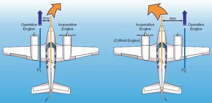
When one engine becomes inoperative, a yawing moment develops, the magnitude of which is equal to the lateral distance of the thrust vector of the operative engine to the center of gravity (C.G.), also called moment arm, multiplied by the thrust of the engine. In addition, a rolling moment might develop due to asymmetrical propulsive lift generated by the wing section behind the operative propeller. These moments yaw and/ or roll the aircraft towards the inoperative engine, a tendency which must be counteracted by the pilot's use of the flight controls: rudder and ailerons. Due to P-factor, a clockwise rotating right-hand propeller on the right wing typically develops its resultant thrust vector at a greater lateral distance from the aircraft's C.G. than the clockwise rotating left-hand propeller (Figure 1). The failure of the left-hand engine will result in a larger remaining yawing moment by the operating right-hand engine, rather than vice versa. Since the operating right-hand engine produces a larger yawing moment, the pilot will need to use larger control deflections in order to maintain aircraft control, or a higher speed. Thus, the failure of the left-hand engine is less desirable than failure of the right-hand engine, and the left-hand engine is called critical.
It is important to note, however, that this example depends upon both propellers rotating clockwise as viewed from the rear. On aircraft with counter-clockwise-rotating propellers (such as the de Havilland Dove), the right engine would be the critical engine.
Most aircraft which have counter-rotating propellers do not have a critical engine defined by the above mechanism, because the two propellers are made to rotate inward from the top of the arc; both engines are equally critical. However, some aircraft, such as the Lockheed P-38 Lightning had propeller rotation purposely reversed to reduce downwash on the central horizontal stabilizer, to make for better gunnery. These engines were both also equally critical, but more critical than inward rotating propellers.[6]
Aircraft with centre line thrust propeller configurations (e.g. the Cessna 337) may still have a critical engine, if failure of one engine (either the front or rear) has more of a negative effect on aircraft control or climb performance than failure of the other engine although the yawing and rolling moments will be small.

Effect of the Critical Engine on Minimum Control Speed VMC
Airworthiness Standards and Certification Specifications (§ 23.149 and § 25.149) require the manufacturer to determine a minimum control speed at which the airplane is controllable after failure of the critical engine and publish this speed in the Limitations Section of the Airplane Flight Manual.[1][2] The published Minimum Control Speeds (VMC's) of the aircraft are measured while the critical engine fails or is inoperative, hence, the effect of the failure of the critical engine is included in the published VMC's. When any one of the other engines fails or is inoperative, the actual VMC that the pilot experiences in-flight will be a bit lower, which is safer, but this decrement is not documented. The critical engine is just one of the factors that influences the VMC's of the aircraft. The published VMC's are therefore safe, whatever engine fails or is inoperative. Hence, (airline) pilots should not have to know about the criticality of an engine. The critical engine is defined in Aviation Regulations for use by airplane tail design engineers for sizing the tail, and by experimental test pilots for measuring VMC's in-flight. Other factors, like bank angle and thrust, have a much greater effect on VMC's than the difference of a critical and a non-critical engine. Please refer to the minimum control speed article for detailed information.

An interesting case is the Airbus A400M. Unique to the propulsion system of this airplane are the counter-rotating propellers on both wings; both propellers on each wing rotate in opposite direction to each other, down in-between. If both engines on a wing are operative, the shift of the thrust vector with increasing angle of attack is always towards the other engine on the same wing. The effect is that the resultant thrust vector of both engines on the same wing does not shift as the angle of attack of the airplane increases, as long as both engines are operating. There is no overall P-factor; there will be no difference in magnitude of remaining thrust yawing moments after failure of either engine #1 or #4 with increasing AOA, only in direction left or right. This means that the minimum control speed during takeoff (VMC) and/ or in the Air (VMCA) after failure of either one of the outboard engines will be the same, unless (boosting) systems, that may be required for controlling the airplane, are installed on only one of the outboard engines. This airplane does therefore not have a left- or right-hand critical engine; both out-board engines are equally critical.
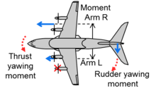
If an outboard engine fails, for instance #1 as shown in Figure 2, the moment arm of the vector of the remaining thrust on that wing reduces from in between the engines to a bit outside of the remaining inboard engine. The vector itself is 50% of the opposite thrust vector. The resulting thrust yawing moment is much smaller than would be the case for conventional propeller rotation. The maximum rudder yawing moment to counteract the asymmetrical thrust can be smaller and consequently, the size of vertical tail of this airplane can be smaller. There is however one very important condition: the feathering system of the big 8-bladed, 17.5 ft (5.33 m) diameter and therefore high drag propellers must be automatic, very rapid and failure free to ensure the lowest possible propeller drag following a propulsion system malfunction. If not, a failure of the feathering system of an outboard engine will increase propeller drag, which in turn enhances the thrust yawing moment considerably therewith increasing actual VMC(A). The control power generated by the small vertical tail and rudder alone is low by the small design. Only rapid reduction of thrust of the opposite engine, or (increased) airspeed can restore the required control power to maintain straight flight following the failure of a feathering system. Designing and approving the feathering system for this airplane will be a real challenge to the design engineers and the certification authorities.
On airplanes with very powerful engines, an asymmetrical thrust problem is also being solved by applying automatic thrust asymmetry compensation, but this has consequences for takeoff performance as well.
Elimination
The Rutan Boomerang is an asymmetrical aircraft designed with engines with slightly different power outputs to produce an aircraft which eliminates the dangers of asymmetric thrust in the event of failure of either of its two engines.
References
- 1 2 Federal Aviation Administration, USA. "Federal Aviation Regulations (FAR)". Title 14, Part 23 and Part 25, § 149. Retrieved Oct 28, 2013.
- 1 2 European Aviation Safety Agency. "Certification Specifications (CS)". CS-23 and CS-25, § 149. Retrieved Oct 28, 2013.
- ↑ Federal Aviation Administration, USA. "Advisory Circular 23-8C, Flight Test Guide" (PDF). Retrieved Oct 28, 2013.
- ↑ Federal Aviation Administration, USA. "Advisory Circular 25-7B. Flight Test Guide" (PDF). Retrieved Oct 28, 2013.
- ↑ European Aviation Safety Agency. "Certification Specification 23 Flight Test Guide" (PDF). Retrieved Oct 28, 2013.
- ↑ Garrison, Peter (February 2005). "P Factor, Torque and the Critical Engine". Flying. 132 (2): 99. ISSN 0015-4806.
Airplane Flying Handbook. U.S. Government Printing Office, Washington D.C.: U.S. Federal Aviation Administration. 2004. pp. 12–27 to 12–28. FAA-8083-3A.