Digital signal
A digital signal is a signal that represents a sequence of discrete values.[1][2] A logic signal is a digital signal with only two possible values,[3][4] and describes an arbitrary bit stream. Other types of digital signals can represent three-valued logic or higher valued logics.
A digital signal is a physical quantity that alternates between a discrete set of waveforms.[5] Alternatively, a digital signal may be considered to be the sequence of codes represented by such a physical quantity.[6] The physical quantity may be a variable electric current or voltage, the intensity, phase or polarization of an optical or other electromagnetic field, acoustic pressure, the magnetization of a magnetic storage media, etcetera. Digital signals are present in all digital electronics, notably computing equipment and data transmission.

With digital signals, system noise, provided it is not too great, will not affect system operation whereas noise always degrades the operation of analog signals to some degree.
Definitions
The term digital signal has related definitions in different contexts:
In digital electronics
In digital electronics a digital signal is a pulse train (a pulse amplitude modulated signal), i.e. a sequence of fixed-width square-wave electrical pulses or light pulses, each occupying one of a discrete number of levels of amplitude.[7][8] A special case is a logic signal or a binary signal, which varies between a low and a high signal level.
In signal processing
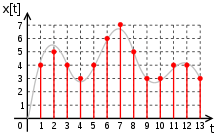
In digital signal processing, a digital signal is a representation of a physical signal that is a sampled and quantified. A digital signal is an abstraction which is discrete in time and amplitude. The signal's value only exists at regular time intervals, since only the values of the corresponding physical signal at those sampled moments are significant for further digital processing. The digital signal is a sequence of codes drawn from a finite set of values.[6] The digital signal may be stored, processed or transmitted physically as a pulse code modulation (PCM) signal.

In communications

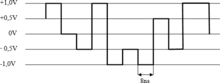
In digital communications, a digital signal is a continuous-time physical signal, alternating between a discrete number of waveforms,[5] representing a bit stream message. The shape of the waveform depends the transmission scheme, which may be either:
- a line coding scheme, which produces a pulse-modulated signal, allowing baseband transmission; or
- a digital modulation scheme, allowing passband transmission over long wires or over a limited radio frequency band. Such a carrier-modulated sine wave is considered a digital signal in literature on digital communications and data transmission,[9] but considered as a bit-stream converted to an analog signal in electronics and computer networking.[10]
Logic signal
In computer architecture and other digital systems, a waveform that switches between two voltage levels (or less commonly, other waveforms) representing the two states of a Boolean value (0 and 1, or Low and High, or false and true) is referred to as a digital signal or logic signal or binary signal when it is interpreted in terms of only two possible digits.
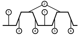
The clock signal is a special digital signal that is used to synchronize many (but not all) digital circuits. The image shown can be considered the waveform of a clock signal. Logic changes are triggered either by the rising edge or the falling edge.
The given diagram is an example of the practical pulse and therefore we have introduced two new terms that are:
- Rising edge: the transition from a low voltage (level 1 in the diagram) to a high voltage (level 2).
- Falling edge: the transition from a high voltage to a low one.
Although in a highly simplified and idealized model of a digital circuit we may wish for these transitions to occur instantaneously, no real world circuit is purely resistive and therefore no circuit can instantly change voltage levels. This means that during a short, finite transition time the output may not properly reflect the input, and will not correspond to either a logically high or low voltage.
Logic voltage levels
The two states of a wire are usually represented by some measurement of an electrical property: Voltage is the most common, but current is used in some logic families. A threshold is designed for each logic family. When below that threshold, the signal is low, when above high.
Modulation
To create a digital signal, an analog signal must be modulated with a control signal to produce it. As we have already seen, the simplest modulation, a type of unipolar line coding is simply to switch on and off a DC signal, so that high voltages are a '1' and low voltages are '0'.
In digital radio schemes one or more carrier waves are amplitude or frequency or phase modulated with a signal to produce a digital signal suitable for transmission.
In Asymmetric Digital Subscriber Line over telephone wires, ADSL does not primarily use binary logic; the digital signals for individual carriers are modulated with different valued logics, depending on the Shannon capacity of the individual channel.
Clocking

Often digital signals are "sampled" by a clock signal at regular intervals by passing the signal through an "edge sensitive" flip-flop. When this is done the input is measured at those points in time, and the signal from that time is passed through to the output and the output is then held steady till the next clock.
This process is the basis of synchronous logic, and the system is also used in digital signal processing.
However, asynchronous logic also exists, which uses no single clock, and generally operates more quickly, and may use less power, but is significantly harder to design.
See also
References
- ↑ Digital Design with CPLD Applications and VHDL By Robert K. Dueck: "A digital representation can have only specific discrete values"
- ↑ Proakis, John G.; Manolakis, Dimitris G. (2007-01-01). Digital Signal Processing. Pearson Prentice Hall. ISBN 9780131873742.
- ↑ "Digital Signal". Retrieved 2016-08-13.
- ↑ Paul Horowitz; Winfield Hill (2015). The Art of Electronics. Cambridge University Press. ISBN 9780521809269.
- 1 2 Analogue and Digital Communication Techniques: "A digital signal is a complex waveform and can be defined as a discrete waveform having a finite set of levels"
- 1 2 Vinod Kumar Khanna, Digital Signal Processing, 2009: A digital signal is a special form of discrete-time signal which is discrete in both time and amplitude, obtained by permitting each value (sample) of a discrete-time signal to acquire a finite set of values (quantization), assigning it a numerical symbol according to a code ... A digital signal is a sequence or list of numbers drawn from a finite set.
- ↑ B. SOMANATHAN NAIR, Digital electronics and logic design 2002: "Digital signals are fixed-width pulses, which occupy only one of two levels of amplitude."
- ↑ Joseph Migga Kizza, Computer Network Security 2005
- ↑ J.S.Chitode, Communication Systems, 2008: "When a digital signal is transmitted over a long distance, it needs CW modulation."
- ↑ Fred Halsall, Computer Networking and the Internet: "In order to transmit a digital signal over an analog subscriber line, modulated transmission must be used; thas is the electrical signal that represents the binary bit stream of the source (digital) output must first be converted to an analog signal that is compatible with a (telephony) speech signal."
Line coding (digital baseband transmission) | ||
|---|---|---|
| Main articles | 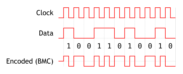 | |
| Basic line codes | ||
| Extended line codes | ||
| Optical line codes | ||
| ||