Hall-effect thruster

In spacecraft propulsion, a Hall-effect thruster (HET) is a type of ion thruster in which the propellant is accelerated by an electric field. Hall-effect thrusters trap electrons in a magnetic field and then use the electrons to ionize propellant, efficiently accelerate the ions to produce thrust, and neutralize the ions in the plume. Hall-effect thrusters are sometimes referred to as Hall thrusters or Hall-current thrusters. Hall thrusters are often regarded as a moderate specific impulse (1,600 s) space propulsion technology. The Hall-effect thruster has benefited from considerable theoretical and experimental research since the 1960s.[1]
Hall thrusters operate on a variety of propellants, the most common being xenon. Other propellants of interest include krypton, argon, bismuth, iodine, magnesium, and zinc.
Hall thrusters are able to accelerate their exhaust to speeds between 10 and 80 km/s (1,000–8,000 s specific impulse), with most models operating between 15 and 30 km/s (1,500–3,000 s specific impulse). The thrust produced by a Hall thruster varies depending on the power level. Devices operating at 1.35 kW produce about 83 mN of thrust. High-power models have demonstrated up to 3 N in the laboratory. Power levels up to 100 kW have been demonstrated by xenon Hall thrusters.
As of 2009, Hall-effect thrusters ranged in input power levels from 1.35 to 10 kilowatts and had exhaust velocities of 10–50 kilometers per second, with thrust of 40–600 millinewtons and efficiency in the range of 45–60 percent.[2]
The applications of Hall-effect thrusters include control of the orientation and position of orbiting satellites and use as a main propulsion engine for medium-size robotic space vehicles.[2]
History
Hall thrusters were studied independently in the United States and the Soviet Union. They were first described publicly in the US in the early 1960s.[3][4][5] However, the Hall thruster was first developed into an efficient propulsion device in the Soviet Union. In the US, scientists focused instead on developing gridded ion thrusters.
Two types of Hall thrusters were developed in the Soviet Union:
- thrusters with wide acceleration zone, SPT (Russian: СПД, стационарный плазменный двигатель; English: SPT, Stationary Plasma Thruster) at Design Bureau Fakel
- thrusters with narrow acceleration zone, DAS (Russian: ДАС, двигатель с анодным слоем; English: TAL, Thruster with Anode Layer), at the Central Research Institute for Machine Building (TsNIIMASH).
The SPT design was largely the work of A. I. Morozov.[6][7] The first SPT to operate in space, an SPT-50 aboard a Soviet Meteor spacecraft, was launched December 1971. They were mainly used for satellite stabilization in North-South and in East-West directions. Since then until the late 1990s 118 SPT engines completed their mission and some 50 continued to be operated. Thrust of the first generation of SPT engines, SPT-50 and SPT-60 was 20 and 30 mN respectively. In 1982, SPT-70 and SPT-100 were introduced, their thrusts being 40 and 83 mN, respectively. In the post-Soviet Russia high-power (a few kilowatts) SPT-140, SPT-160, SPT-200, T-160 and low-power (less than 500 W) SPT-35 were introduced.[8]
Soviet and Russian TAL-type thrusters include the D-38, D-55, D-80, and D-100.[8]
Soviet-built thrusters were introduced to the West in 1992 after a team of electric propulsion specialists from NASA's Jet Propulsion Laboratory, Glenn Research Center, and the Air Force Research Laboratory, under the support of the Ballistic Missile Defense Organization, visited Russian laboratories and experimentally evaluated the SPT-100 (i.e., a 100 mm diameter SPT thruster). Over 200 Hall thrusters have been flown on Soviet/Russian satellites in the past thirty years. No failures have ever occurred on orbit. Hall thruster continue to be used on Russian spacecraft and have also flown on European and American spacecraft. Space Systems/Loral, an American commercial satellite manufacturer, now flies Fakel SPT-100's on their GEO communications spacecraft.
Since their introduction to the west in the early 1990s, Hall thrusters have been the subject of a large number of research efforts throughout the United States, France, Italy, Japan, and Russia (with many smaller efforts scattered in various countries across the globe). Hall thruster research in the US is conducted at several government laboratories, universities and private companies. Government and government funded centers include NASA's Jet Propulsion Laboratory, NASA's Glenn Research Center, the Air Force Research Laboratory (Edwards AFB, CA), and The Aerospace Corporation. Universities include the US Air Force Institute of Technology, University of Michigan, Stanford University, The Massachusetts Institute of Technology, Princeton University, Michigan Technological University, and Georgia Tech. A considerable amount of development is being conducted in industry, such as Aerojet and Busek in the USA, SNECMA in France and in Italy.[9] Also, TÜBITAK Space of Turkey has recently developed a Hall thruster prototype. This will be further enhanced and used in satellites and possible future spacecrafts.[10][11]
The first use of Hall thrusters on lunar orbit was the European Space Agency (ESA) lunar mission SMART-1 in 2003.
On a western satellite Hall thrusters were first demonstrated on the Naval Research Laboratory (NRL) STEX spacecraft, which flew the Russian D-55. The first American Hall thruster to fly in space was the Busek BHT-200 on TacSat-2 technology demonstration spacecraft. The first flight of an American Hall thruster on an operational mission, was the Aerojet BPT-4000, which launched August 2010 on the military Advanced Extremely High Frequency GEO communications satellite. At 4.5 kW, the BPT-4000 is also the highest power Hall thruster ever flown in space. Besides the usual stationkeeping tasks, the BPT-4000 is also providing orbit raising capability to the spacecraft. Several countries worldwide continue efforts to qualify Hall thruster technology for commercial uses.
Operation
The essential working principle of the Hall thruster is that it uses an electrostatic potential to accelerate ions up to high speeds. In a Hall thruster the attractive negative charge is provided by an electron plasma at the open end of the thruster instead of a grid. A radial magnetic field of about 100–300 G (0.01–0.03 T) is used to confine the electrons, where the combination of the radial magnetic field and axial electric field cause the electrons to drift in azimuth thus forming the Hall current from which the device gets its name.
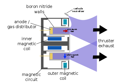
A schematic of a Hall thruster is shown in the adjacent image. An electric potential between 150 and 800 volts is applied between the anode and cathode.
The central spike forms one pole of an electromagnet and is surrounded by an annular space, and around that is the other pole of the electromagnet, with a radial magnetic field in between.
The propellant, such as Xenon gas, is fed through the anode, which has numerous small holes in it to act as a gas distributor. Xenon propellant is used because of its high atomic weight and low ionization potential. As the neutral Xenon atoms diffuse into the channel of the thruster, they are ionized by collisions with circulating high-energy electrons (typically 10–40 eV, or about 10% of the discharge voltage). Once ionized, the Xenon ions typically have a charge of +1, though a small fraction (~20%) have +2.
The Xenon ions are then accelerated by the electric field between the anode and the cathode. For discharge voltages of 300 V, the ions reach speeds of around 15 km/s (9.3 mps) for a specific impulse of 1,500 seconds (15 kN·s/kg). Upon exiting, however, the ions pull an equal number of electrons with them, creating a plasma plume with no net charge.
The radial magnetic field is designed to be strong enough to substantially deflect the low-mass electrons, but not the high-mass ions, which have a much larger gyroradius and are hardly impeded. The majority of electrons are thus stuck orbiting in the region of high radial magnetic field near the thruster exit plane, trapped in E×B (axial electric field and radial magnetic field). This orbital rotation of the electrons is a circulating Hall current, and it is from this that the Hall thruster gets its name. Collisions with other particles and walls, as well as plasma instabilities, allow some of the electrons to be freed from the magnetic field, and they drift towards the anode.
About 20–30% of the discharge current is an electron current, which does not produce thrust, thus limiting the energetic efficiency of the thruster; the other 70–80% of the current is in the ions. Because the majority of electrons are trapped in the Hall current, they have a long residence time inside the thruster and are able to ionize almost all of the Xenon propellant, allowing mass utilizations of 90–99%. The mass utilization efficiency of the thruster is thus around 90%, while the discharge current efficiency is around 70%, for a combined thruster efficiency of around 63% (= 90% × 70%). Modern Hall thrusters have achieved efficiencies as high as 75% through advanced designs.
Compared to chemical rockets, the thrust is very small, on the order of 83 mN for a typical thruster operating at 300 V, 1.5 kW. For comparison, the weight of a coin like the U.S. quarter or a 20-cent Euro coin is approximately 60 mN. As with all forms of electrically powered spacecraft propulsion, thrust is limited by available power, efficiency, and specific impulse.
However, Hall thrusters operate at the high specific impulses that is typical for electric propulsion. One particular advantage of Hall thrusters, as compared to a gridded ion thruster, is that the generation and acceleration of the ions takes place in a quasi-neutral plasma, so there is no Child-Langmuir charge (space charge) saturated current limitation on the thrust density. This allows much smaller thrusters compared to gridded ion thrusters.
Another advantage is that these thrusters can use a wider variety of propellants supplied to the anode, even oxygen, although something easily ionized is needed at the cathode.[12]
Cylindrical Hall thrusters
Although conventional (annular) Hall thrusters are efficient in the kilowatt power regime, they become inefficient when scaled to small sizes. This is due to the difficulties associated with holding the performance scaling parameters constant while decreasing the channel size and increasing the applied magnetic field strength. This led to the design of the cylindrical Hall thruster. The cylindrical Hall thruster can be more readily scaled to smaller sizes due to its nonconventional discharge-chamber geometry and associated magnetic field profile.[13][14][15] The cylindrical Hall thruster more readily lends itself to miniaturization and low-power operation than a conventional (annular) Hall thruster. The primary reason for cylindrical Hall thrusters is that it is difficult to achieve a regular Hall thruster that operates over a broad envelope from ~1 kW down to ~100 W while maintaining an efficiency of 45-55%.[16]
Applications
Hall thrusters have been flying in space since December 1971 when the Soviets launched an SPT-50 on a Meteor satellite.[17] Over 240 thrusters have flown in space since that time with a 100% success rate.[18] Hall thrusters are now routinely flown on commercial GEO communications satellites where they are used for orbital insertion and stationkeeping.
The first Hall thruster to fly on a western satellite was a Russian D-55 built by TsNIIMASH, on the NRO's STEX spacecraft, launched on October 3, 1998.[19]
The solar electric propulsion system of the European Space Agency's SMART-1 spacecraft used a Snecma PPS-1350-G Hall thruster.[20] SMART-1 was a technology demonstration mission that orbited the Moon. This use of the PPS-1350-G, starting on September 28, 2003, was the first use of a Hall thruster outside geosynchronous earth orbit (GEO). Unlike most Hall thruster propulsion systems used in commercial applications, the Hall thruster on SMART-1 could be throttled over a range of power, specific impulse, and thrust.[21]
- Discharge power: 0.46–1.19 kW
- Specific impulse: 1,100–1,600 s
- Thrust: 30–70 mN
References
- ↑ Hofer, Richard R. "Development and Characterization of High-Efficiency, High-Specific Impulse Xenon Hall Thrusters". NASA/CR—2004-21309. NASA STI Program. Retrieved 17 October 2011.
- 1 2 Choueiri, Edgar Y. (2009). "New Dawn for Electric Rockets". Scientific American. 300: 58–65. doi:10.1038/scientificamerican0209-58.
- ↑ Janes, G.; Dotson, J.; Wilson, T. (1962). Momentum transfer through magnetic fields. Proceedings of third symposium on advanced propulsion concepts. 2. Cincinnati, OH, USA. pp. 153–175.
- ↑ Meyerand, RG. (1962). Momentum Transfer Through the Electric Fields. Proceedings of Third Symposium on Advanced Propulsion Concepts. 1. Cincinnati, OH, USA. pp. 177–190.
- ↑ Seikel, GR. (1962). Generation of Thrust – Electromagnetic Thrusters. Proceedings of the NASA-University Conference on the Science and Technology of Space Exploration. 2. Chicago, IL, USA. pp. 171–176.
- ↑ "Hall thrusters". 2004-01-14. Archived from the original on February 28, 2004.
- ↑ Morozov, A.I. (March 2003). "The conceptual development of stationary plasma thrusters". Plasma Physics Reports. Nauka/Interperiodica. 29 (3): 235–250. Bibcode:2003PlPhR..29..235M. doi:10.1134/1.1561119.
- 1 2 "Native Electric Propulsion Engines Today" (in Russian). Novosti Kosmonavtiki. 1999. Archived from the original on 6 June 2011.
- ↑ ALTA
- ↑ TÜBITAK Hale
- ↑ Plasmacongress
- ↑ "Hall-Effect Stationary Plasma thrusters". Electric Propulsion for Inter-Orbital Vehicles. Retrieved 2014-06-16.
- ↑ Y. Raitses; N. J. Fisch. "Parametric Investigations of a Nonconventional Hall Thruster" (PDF). Physics of Plasmas, 8, 2579 (2001).
- ↑ A. Smirnov; Y. Raitses; N.J. Fisch. "Experimental and theoretical studies of cylindrical Hall thrusters" (PDF). Physics of Plasmas 14, 057106 (2007).
- ↑ Polzin, K. A.; Raitses, Y.; Gayoso, J. C.; Fisch, N. J. "Comparisons in Performance of Electromagnet and Permanent-Magnet Cylindrical Hall-Effect Thrusters". NASA Technical Reports Server. Marchall Space Flight Center. Retrieved 17 October 2011.
- ↑ Polzin, K. A.; Raitses, Y.; Merino, E.; Fisch, N. J. "Preliminary Results of Performance Measurements on a Cylindrical Hall-Effect Thruster with Magnetic Field Generated by Permanent Magnets". NASA Technical Reports Server. Princeton Plasma Physics Laboratory. Retrieved 17 October 2011.
- ↑ Turner, Martin J. L. (5 November 2008). Rocket and Spacecraft Propulsion: Principles, Practice and New Developments, page 197. Springer Science & Business Media. Retrieved 28 October 2015.
- ↑
 This article incorporates public domain material from the National Aeronautics and Space Administration document ""In-space propulsion systems roadmap." (April 2012)." by Meyer, Mike, et al.
- ↑ "National Reconnaissance Office Satellite Successfully Launched" (PDF). Naval Research Laboratory (Press Release). October 3, 1998.
- ↑ Cornu, Nicolas; Marchandise, Frédéric; Darnon, Franck; Estublier, Denis (2007). PPS®1350 Qualification Demonstration: 10500 hrs on the Ground and 5000 hrs in Flight. 43rd AIAA/ASME/SAE/ASEE Joint Propulsion Conference & Exhibit. Cincinnati, OH, USA. doi:10.2514/6.2007-5197.
- ↑ "Ion engine gets SMART-1 to the Moon: Electric Propulsion Subsystem". ESA. August 31, 2006. Retrieved 2011-07-25.
External links
- Edgar Y. (2009). New dawn of electric rocket. The Hall thruster
- NASA Jet Propulsion Laboratory
- SITAEL S.p.A. (Italy) – Page presenting Hall effect thruster products & data sheets.
- Aerojet (Redmond, WA USA) – Hall-thruster vendor
- Busek (Natick, MA USA) – Hall-thruster vendor
- Experimental Design Bureau Fakel (Kaliningrad, Russia) – Hall-thruster vendor
- MIT Space Propulsion Laboratory
- Michigan Tech. Univ. Ion Space Propulsion Laboratory
- Georgia Institute of Technology High-Power Electric Propulsion Laboratory (HPEPL)
- Colorado State University Electric Propulsion & Plasma Engineering (CEPPE) Laboratory
- University of Michigan Plasmadynamics and Electric Propulsion Laboratory (PEPL)
- NASA Glenn Research Center Hall Thruster Program
- Princeton Plasma Physics Laboratory page on Hall Thrusters
- Snecma SA (France) page on PPS-1350 Hall thruster
- ESA page on Hall thrusters
| Chemical rockets |
| ||||||||||||||
|---|---|---|---|---|---|---|---|---|---|---|---|---|---|---|---|
| Electrical thrusters |
| ||||||||||||||
| Nuclear propulsion |
| ||||||||||||||
| Other | |||||||||||||||