History of the steam engine
The first recorded rudimentary steam engine was the aeolipile described by Heron of Alexandria in the 1st century AD.[1] Starting in the 12th century, a number of steam-powered devices were experimented with or proposed. In 1712 Thomas Newcomen's atmospheric engine became the first commercially successful engine using the principle of the piston and cylinder, which was the fundamental type steam engine used until the early 20th century. The steam engine was used to pump water out of coal mines
During the industrial revolution, steam engines started to replace water and wind power, and eventually became the dominant source of power in the late 19th century and remaining so into the early decades of the 20th century, when the more efficient steam turbine and the internal combustion engine resulted in the rapid replacement of the steam engines. The steam turbine has become the most common method by which electrical power generators are driven.[2] Investigations are being made into the practicalities of reviving the reciprocating steam engine as the basis for a new wave of advanced steam technology.
Precursors
Early uses of steam power

The earliest known rudimentary steam engine and reaction steam turbine, the aeolipile, is described by a Greek mathematician and engineer named Heron of Alexandria (Heron) in 1st century Roman Egypt, as recorded in his manuscript Spiritalia seu Pneumatica.[3][4] Steam ejected tangentially from nozzles caused a pivoted ball to rotate. Its thermal efficiency was low. This suggests that the conversion of steam pressure into mechanical movement was known in Roman Egypt in the 1st century. Hero also devised a machine that used air heated in an altar fire to displace a quantity of water from a closed vessel. The weight of the water was made to pull a hidden rope to operate temple doors.[4][5] Some historians have conflated the two inventions to assert, incorrectly, that the aeolipile was capable of useful work.
According to William of Malmesbury, in 1125, Reims was home to a church that had an organ powered by air escaping from compression "by heated water", apparently designed and constructed by professor Gerbertus.[4][6]
Among the papers of Leonardo da Vinci dating to the late 15th century is the design for a steam-powered cannon called the Architonnerre which works by the sudden influx of hot water into a sealed red hot cannon.[7]
A rudimentary impact steam turbine was described in 1551 by Taqi al-Din, a philosopher, astronomer and engineer in 16th century Ottoman Egypt, who described a method for rotating a spit by means of a jet of steam playing on rotary vanes around the periphery of a wheel. A similar device for rotating a spit was also later described by John Wilkins in 1648.[8] These devices were then called "mills" but are now known as steam jacks. Another similar rudimentary steam turbine is shown by Giovanni Branca, an Italian engineer, in 1629 for turning a cylindrical escapement device that alternately lifted and let fall a pair of pestles working in mortars.[9] The steam flow of these early steam turbines, however, was not concentrated and most of its energy was dissipated in all directions. This would have led to a great waste of energy and so they were never seriously considered for industrial use.
In 1605 French mathematician Florence Rivault in his treatise on artillery wrote on his discovery that water, if confined in a bombshell and heated, would explode the shells.[10]
In 1606, the Spaniard, Jerónimo de Ayanz y Beaumont demonstrated and was granted a patent for a steam powered water pump. The pump was successfully used to drain the inundated mines of Guadalcanal, Spain.[11]
Development of the commercial steam engine
“The discoveries that, when brought together by Thomas Newcomen in 1712, resulted in the steam engine were:"[12]
- The concept of a vacuum (i.e. a reduction in pressure below ambient)
- The concept of pressure
- Techniques for creating a vacuum
- A means for generating steam
- The piston and cylinder
In 1643 Evangelista Torricelli conducted experiments on suction lift water pumps to test their limits, which was about 32 feet (atmospheric pressure is 32.9 feet or 10.03 meters). He devised an experiment using a tube filled with mercury and inverted in a bowl of mercury (a barometer) and observed an empty space above the column of mercury, which he theorized contained nothing, that is, a vacuum.[13]
Influenced by Torricelli, Otto von Guericke invented a vacuum pump by modifying an air gun pump. Guericke put on a demonstration in 1654 in Magdeburg, Germany, where he was mayor. Two copper hemispheres were fitted together and air was pumped out. Weights strapped to the hemispheres could not pull them apart until the air valve was opened. The experiment was repeated in 1656 using two teams of 8 horses each, which could not separate the Magdeburg hemispheres.[13]
Gaspar Schott was the first to describe the hemisphere experiment in his Mechanica Hydraulico-Pneumatica (1657).[13]
After reading Schott’s book, Robert Boyle built and improved vacuum pump and conducted related experiments.[13]
Denis Papin became interested in using a vacuum to generate motive power while working with Christiaan Huygens and Gottfried Leibniz in Paris in 1663. Papin worked for Robert Boyle from 1676 to 1679, publishing an account of his work in Continuation of New Experiments (1680) and gave a presentation to Royal Society in 1689. From 1690 on Papin began experimenting with a piston to produce power with steam, building model steam engines. He experimented with atmospheric and pressure steam engines, publishing his results in 1707.[13]
In 1663 Edward Somerset, 2nd Marquess of Worcester published a book of 100 inventions which described a method for raising water between floors employing a similar principle to that of a coffee percolator. His system was the first to separate the boiler (a heated cannon barrel) from the pumping action. Water was admitted into a reinforced barrel from a cistern, and then a valve was opened to admit steam from a separate boiler. The pressure built over the top of the water, driving it up a pipe.[14] He installed his steam-powered device on the wall of the Great Tower at Raglan Castle to supply water through the tower. The grooves in the wall where the engine was installed were still to be seen in the 19th century. However, no one was prepared to risk money for such a revolutionary concept, and without backers the machine remained undeveloped.[13][15]
Samuel Morland, a mathematician and inventor who worked on pumps, left notes at the Vauxhall Ordinance Office on a steam pump design that Thomas Savery read. In 1698 Savery built a steam pump called “The Miner’s Friend.” It employed both vacuum and pressure. These were used for low horsepower service for a number of years.[13]
Thomas Newcomen was a merchant who dealt in cast iron goods. Newcomen’s engine was based on the piston and cylinder design proposed by Papin. In Newcomen's engine steam was condensed by water sprayed inside the cylinder, causing atmospheric pressure to move the piston. Newcomen’s first engine installed for pumping in a mine in 1712 at Dudley Castle in Staffordshire.[13]
Cylinders
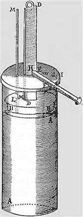
Denis Papin (22 August 1647 – c. 1712) was a French physicist, mathematician and inventor, best known for his pioneering invention of the steam digester, the forerunner of the pressure cooker. In the mid-1670s Papin collaborated with the Dutch physicist Christiaan Huygens on an engine which drove out the air from a cylinder by exploding gunpowder inside it. Realising the incompleteness of the vacuum produced by this means and on moving to England in 1680, Papin devised a version of the same cylinder that obtained a more complete vacuum from boiling water and then allowing the steam to condense; in this way he was able to raise weights by attaching the end of the piston to a rope passing over a pulley. As a demonstration model the system worked, but in order to repeat the process the whole apparatus had to be dismantled and reassembled. Papin quickly saw that to make an automatic cycle the steam would have to be generated separately in a boiler; however, he did not take the project further. Papin also designed a paddle boat driven by a jet playing on a mill-wheel in a combination of Taqi al Din and Savery's conceptions and he is also credited with a number of significant devices such as the safety valve. Papin's years of research into the problems of harnessing steam was to play a key part in the development of the first successful industrial engines that soon followed his death.
Savery steam pump
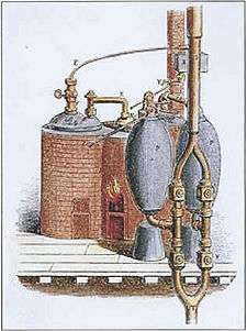
The first steam engine to be applied industrially was the "fire-engine" or "Miner's Friend", designed by Thomas Savery in 1698. This was a pistonless steam pump, similar to the one developed by Worcester. Savery made two key contributions that greatly improved the practicality of the design. First, in order to allow the water supply to be placed below the engine, he used condensed steam to produce a partial vacuum in the pumping reservoir (the barrel in Worcester's example), and using that to pull the water upward. Secondly, in order to rapidly cool the steam to produce the vacuum, he ran cold water over the reservoir.
Operation required several valves; when the reservoir was empty at the start of a cycle a valve was opened to admit steam. The valve was closed to seal the reservoir and the cooling water valve turned on to condense the steam and create a partial vacuum. A supply valve was opened, pulling water upward into the reservoir, and the typical engine could pull water up to 20 feet.[16] This was closed and the steam valve reopened, building pressure over the water and pumping it upward, as in the Worcester design. The cycle essentially doubled the distance that water could be pumped for any given pressure of steam, and production examples raised water about 40 feet.[16]
Savery's engine solved a problem that had only recently become a serious one; raising water out of the mines in southern England as they reached greater depths. Savery's engine was somewhat less efficient than Newcomen's, but this was compensated for by the fact that the separate pump used by the Newcomen engine was inefficient, giving the two engines roughly the same efficiency of 6 million foot pounds per bushel of coal (less than 1%).[17] Nor was the Savery engine very safe because part of its cycle required steam under pressure supplied by a boiler, and given the technology of the period the pressure vessel could not be made strong enough and so was prone to explosion.[18] The explosion of one of his pumps at Broad Waters (near Wednesbury), about 1705, probably marks the end of attempts to exploit his invention.[19]
The Savery engine was less expensive than Newcomen's and was produced in smaller sizes.[20] Some builders were manufacturing improved versions of the Savery engine until late in the 18th century.[17] Bento de Moura Portugal, FRS, introduced an ingenious improvement of Savery's construction "to render it capable of working itself", as described by John Smeaton in the Philosophical Transactions published in 1751.[21]
Atmospheric condensing engines
Newcomen "atmospheric" engine
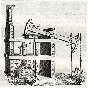

It was Thomas Newcomen with his "atmospheric-engine" of 1712 who can be said to have brought together most of the essential elements established by Papin in order to develop the first practical steam engine for which there could be a commercial demand. This took the shape of a reciprocating beam engine installed at surface level driving a succession of pumps at one end of the beam. The engine, attached by chains from other end of the beam, worked on the atmospheric, or vacuum principle.[23]
Newcomen's design used some elements of earlier concepts. Like the Savery design, Newcomen's engine used steam, cooled with water, to create a vacuum. Unlike Savery's pump, however, Newcomen used the vacuum to pull on a piston instead of pulling on water directly. The upper end of the cylinder was open to the atmospheric pressure, and when the vacuum formed, the atmospheric pressure above the piston pushed it down into the cylinder. The piston was lubricated and sealed by a trickle of water from the same cistern that supplied the cooling water. Further, to improve the cooling effect, he sprayed water directly into the cylinder.
The piston was attached by a chain to a large pivoted beam. When the piston pulled the beam, the other side of the beam was pulled upward. This end was attached to a rod that pulled on a series of conventional pump handles in the mine. At the end of this power stroke, the steam valve was reopened, and the weight of the pump rods pulled the beam down, lifting the piston and drawing steam into the cylinder again.
Using the piston and beam allowed the Newcomen engine to power pumps at different levels throughout the mine, as well as eliminating the need for any high-pressure steam. The entire system was isolated to a single building on the surface. Although inefficient and extremely heavy on coal (compared to later engines), these engines raised far greater volumes of water and from greater depths than had previously been possible.[18] Over 100 Newcomen engines were installed around England by 1735, and it is estimated that as many as 2,000 were in operation by 1800 (including Watt versions).
John Smeaton made numerous improvements to the Newcomen engine, notably the seals, and by improving these was able to almost triple their efficiency. He also preferred to use wheels instead of beams for transferring power from the cylinder, which made his engines more compact. Smeaton was the first to develop a rigorous theory of steam engine design of operation. He worked backward from the intended role to calculate the amount of power that would be needed for the task, the size and speed of a cylinder that would provide it, the size of boiler needed to feed it, and the amount of fuel it would consume. These were developed empirically after studying dozens of Newcomen engines in Cornwall and Newcastle, and building an experimental engine of his own at his home in Austhorpe in 1770. By the time the Watt engine was introduced only a few years later, Smeaton had built dozens of ever-larger engines into the 100 hp range.[24]
Watt's separate condenser

While working at the University of Glasgow as an instrument maker and repairman in 1759, James Watt was introduced to the power of steam by Professor John Robison. Fascinated, Watt took to reading everything he could on the subject, and independently developed the concept of latent heat, only recently published by Joseph Black at the same university. When Watt learned that the University owned a small working model of a Newcomen engine, he pressed to have it returned from London where it was being unsuccessfully repaired. Watt repaired the machine, but found it was barely functional even when fully repaired.
After working with the design, Watt concluded that 80% of the steam used by the engine was wasted. Instead of providing motive force, it was instead being used to heat the cylinder. In the Newcomen design, every power stroke was started with a spray of cold water, which not only condensed the steam, but also cooled the walls of the cylinder. This heat had to be replaced before the cylinder would accept steam again. In the Newcomen engine the heat was supplied only by the steam, so when the steam valve was opened again the vast majority condensed on the cold walls as soon as it was admitted to the cylinder. It took a considerable amount of time and steam before the cylinder warmed back up and the steam started to fill it up.
Watt solved the problem of the water spray by removing the cold water to a different cylinder, placed beside the power cylinder. Once the induction stroke was complete a valve was opened between the two, and any steam that entered the cylinder would condense inside this cold cylinder. This would create a vacuum that would pull more of the steam into the cylinder, and so on until the steam was mostly condensed. The valve was then closed, and operation of the main cylinder continued as it would on a conventional Newcomen engine. As the power cylinder remained at operational temperature throughout, the system was ready for another stroke as soon as the piston was pulled back to the top. Maintaining the temperature was a jacket around the cylinder where steam was admitted. Watt produced a working model in 1765.
Convinced that this was a great advance, Watt entered into partnerships to provide venture capital while he worked on the design. Not content with this single improvement, Watt worked tirelessly on a series of other improvements to practically every part of the engine. Watt further improved the system by adding a small vacuum pump to pull the steam out of the cylinder into the condenser, further improving cycle times. A more radical change from the Newcomen design was closing off the top of the cylinder and introducing low-pressure steam above the piston. Now the power was not due to the difference of atmospheric pressure and the vacuum, but the pressure of the steam and the vacuum, a somewhat higher value. On the upward return stroke, the steam on top was transferred through a pipe to the underside of the piston ready to be condensed for the downward stroke. Sealing of the piston on a Newcomen engine had been achieved by maintaining a small quantity of water on its upper side. This was no longer possible in Watt's engine due to the presence of the steam. Watt spent considerable effort to find a seal that worked, eventually obtained by using a mixture of tallow and oil. The piston rod also passed through a gland on the top cylinder cover sealed in a similar way.[25]
The piston sealing problem was due to having no way to produce a sufficiently round cylinder. Watt tried having cylinders bored from cast iron, but they were too out of round. Watt was forced to use a hammered iron cylinder.[26] The following quotation is from Roe (1916):
"When [John] Smeaton first saw the engine he reported to the Society of Engineers that 'neither the tools nor the workmen existed who could manufacture such a complex machine with sufficient precision' "[26]
Watt finally considered the design good enough to release in 1774, and the Watt engine was released to the market. As portions of the design could be easily fitted to existing Newcomen engines, there was no need to build an entirely new engine at the mines. Instead, Watt and his business partner Matthew Boulton licensed the improvements to engine operators, charging them a portion of the money they would save in reduced fuel costs. The design was wildly successful, and the Boulton and Watt company was formed to license the design and help new manufacturers build the engines. The two would later open the Soho Foundry to produce engines of their own.
In 1774 John Wilkinson invented a boring machine with the shaft holding the boring tool supported on both ends, extending through the cylinder, unlike the then used cantilevered borers. With this machine he was able to successfully bore the cylinder for Boulton and Watt's first commercial engine in 1776.[26]
Watt never ceased improving his designs. This further improved the operating cycle speed, introduced governors, automatic valves, double-acting pistons, a variety of rotary power takeoffs and many other improvements. Watt's technology enabled the widespread commercial use of stationary steam engines.[27]
Humphrey Gainsborough produced a model condensing steam engine in the 1760s, which he showed to Richard Lovell Edgeworth, a member of the Lunar Society. Gainsborough believed that Watt had used his ideas for the invention;[28] however James Watt was not a member of the Lunar Society at this period and his many accounts explaining the succession of thought processes leading to the final design would tend to belie this story.
Power was still limited by the low pressure, the displacement of the cylinder, combustion and evaporation rates and condenser capacity. Maximum theoretical efficiency was limited by the relatively low temperature differential on either side of the piston; this meant that for a Watt engine to provide a usable amount of power, the first production engines had to be very large, and were thus expensive to build and install.
Watt double-acting and rotative engines
Watt developed a double-acting engine in which steam drove the piston in both directions, thereby increasing the engine speed and efficiency. The double-acting principle also significantly increased the output of a given physical sized engine.[29][30]
Boulton & Watt developed the reciprocating engine into the rotative type. Unlike the Newcomen engine, the Watt engine could operate smoothly enough to be connected to a drive shaft – via sun and planet gears – to provide rotary power along with double-acting condensing cylinders. The earliest example was built as a demonstrator and was installed in Boulton's factory to work machines for lapping (polishing) buttons or similar. For this reason it was always known as the Lap Engine.[31][32] In early steam engines the piston is usually connected by a rod to a balanced beam, rather than directly to a flywheel, and these engines are therefore known as beam engines.
Early steam engines did not provide constant enough speed for critical operations such as cotton spinning. To control speed the engine was used to pump water for a water wheel, which powered the machinery.[33][34]
High-pressure engines
As the 18th century advanced, the call was for higher pressures; this was strongly resisted by Watt who used the monopoly his patent gave him to prevent others from building high-pressure engines and using them in vehicles. He mistrusted the materials' resistance and the boiler technology of the day.
The important advantages of high-pressure engines were:
- They could be made much smaller than previously for a given power output. There was thus the potential for steam engines to be developed that were small and powerful enough to propel themselves and other objects. As a result, steam power for transportation now became a practicality in the form of ships and land vehicles, which revolutionised cargo businesses, travel, military strategy, and essentially every aspect of society.
- Because of their smaller size, they were much less expensive.
- They did not require the significant quantities of condenser cooling water needed by atmospheric engines.
- They could be designed to run at higher speeds, making them more suitable for powering machinery.
The disadvantages were:
- In the low-pressure range they were less efficient than condensing engines, especially if steam was not used expansively.
- They were more susceptible to boiler explosions.
The main difference between how high-pressure and low-pressure steam engines work is the source of the force that moves the piston. In Newcomen's and Watt's engines, it is the condensation of the steam that creates most of the pressure difference, causing atmospheric pressure (Newcomen) or low-pressure steam (Watt) to push the piston; the internal pressures never greatly exceed atmospheric pressure. In a high-pressure engine, most of the pressure difference is provided by the high-pressure steam from the boiler; the low-pressure side of the piston may be at atmospheric pressure or, if it is connected to a condenser, this only provides a small proportion of the pressure difference.
The first known advocate of "strong steam" was Jacob Leupold in his scheme for an engine that appeared in encyclopaedic works from around 1725. Various projects for steam propelled boats and vehicles also appeared throughout the century one of the most promising being Nicolas-Joseph Cugnot's who demonstrated his "fardier" (steam wagon), in 1769. Whilst the working pressure used for this vehicle is unknown, the small size of the boiler gave insufficient steam production rate to allow the fardier to advance more than a few hundred metres at a time before having to stop to raise steam. Other projects and models were proposed, but as with William Murdoch's model of 1784, many were blocked by Boulton and Watt.
This did not apply in the US, and in 1788 a steamboat built by John Fitch operated in regular commercial service along the Delaware River between Philadelphia, Pennsylvania, and Burlington, New Jersey, carrying as many as 30 passengers. This boat could typically make 7 to 8 miles per hour, and traveled more than 2,000 miles (3,200 km) during its short length of service. The Fitch steamboat was not a commercial success, as this route was adequately covered by relatively good wagon roads. In 1802 William Symington built a practical steamboat, and in 1807 Robert Fulton used a Watt steam engine to power the first commercially successful steamboat.
Oliver Evans in his turn was in favour of "strong steam" which he applied to boat engines and to stationary uses. He was a pioneer of cylindrical boilers; however Evans' boilers did suffer several serious boiler explosions, which tended to lend weight to Watt's qualms. He founded the Pittsburgh Steam Engine Company in 1811 in Pittsburgh, Pennsylvania.[35] The company introduced high-pressure steam engines to the riverboat trade in the Mississippi watershed.
The first high-pressure steam engine was invented in 1800 by Richard Trevithick.[36]
The importance of raising steam under pressure (from a thermodynamic standpoint) is that it attains a higher temperature. Thus, any engine using high-pressure steam operates at a higher temperature and pressure differential than is possible with a low-pressure vacuum engine. The high-pressure engine thus became the basis for most further development of reciprocating steam technology. Even so, around the year 1800, "high pressure" amounted to what today would be considered very low pressure, i.e. 40-50 psi (276-345 kPa), the point being that the high-pressure engine in question was non-condensing, driven solely by the expansive power of the steam, and once that steam had performed work it was usually exhausted at higher-than-atmospheric pressure. The blast of the exhausting steam into the chimney could be exploited to create induced draught through the fire grate and thus increase the rate of burning, hence creating more heat in a smaller furnace, at the expense of creating back pressure on the exhaust side of the piston.
On 21 February 1804, at the Penydarren ironworks at Merthyr Tydfil in South Wales, the first self-propelled railway steam engine or steam locomotive, built by Richard Trevithick, was demonstrated.[37]
Cornish engine and compounding

Around 1811 Richard Trevithick was required to update a Watt pumping engine in order to adapt it to one of his new large cylindrical Cornish boilers. When Trevithick left for South America in 1816, his improvements were continued by William Sims. In a parallel, Arthur Woolf developed a compound engine with two cylinders, so that steam expanded in a high-pressure cylinder before being released into a low-pressure one. Efficiency was further improved by Samuel Groase, who insulated the boiler, engine, and pipes.[38]
Steam pressure above the piston was increased eventually reaching 40 psi (0.28 MPa) or even 50 psi (0.34 MPa) and now provided much of the power for the downward stroke; at the same time condensing was improved. This considerably raised efficiency and further pumping engines on the Cornish system (often known as Cornish engines) continued to be built new throughout the 19th century. Older Watt engines were updated to conform.
The take-up of these Cornish improvements was slow in textile manufacturing areas where coal was cheap, due to the higher capital cost of the engines and the greater wear that they suffered. The change only began in the 1830s, usually by compounding through adding another (high-pressure) cylinder.[39]
Another limitation of early steam engines was speed variability, which made them unsuitable for many textile applications, especially spinning. In order to obtain steady speeds, early steam powered textile mills used the steam engine to pump water to a water wheel, which drove the machinery.[40]
Many of these engines were supplied worldwide and gave reliable and efficient service over a great many years with greatly reduced coal consumption. Some of them were very large and the type continued to be built right down to the 1890s.
Corliss engine
.jpg)
The Corliss steam engine (patented 1849) was called the greatest improvement since James Watt.[41] The Corliss engine had greatly improved speed control and better efficiency, making it suitable to all sorts of industrial applications, including spinning.
Corliss used separate ports for steam supply and exhaust, which prevented the exhaust from cooling the passage used by the hot steam. Corliss also used partially rotating valves that provided quick action, helping to reduce pressure losses. The valves themselves were also a source of reduced friction, especially compared to the slide valve, which typically used 10% of an engine's power.[42]
Corliss used automatic variable cut off. The valve gear controlled engine speed by using the governor to vary the timing of the cut off. This was partly responsible for the efficiency improvement in addition to the better speed control.
Porter-Allen high speed steam engine
.jpg)
The Porter-Allen engine, introduced in 1862, used an advanced valve gear mechanism developed for Porter by Allen, a mechanic of exceptional ability, and was at first generally known as the Allen engine. The high speed engine was a precision machine that was well balanced, achievements made possible by advancements in machine tools and manufacturing technology.[42]
The high speed engine ran at piston speeds from three to five times the speed of ordinary engines. It also had low speed variability. The high speed engine was widely used in sawmills to power circular saws. Later it was used for electrical generation.
The engine had several advantages. It could, in some cases, be directly coupled. If gears or belts and drums were used, they could be much smaller sizes. The engine itself was also small for the amount of power it developed.[42]
Porter greatly improved the fly-ball governor by reducing the rotating weight and adding a weight around the shaft. This significantly improved speed control. Porter's governor became the leading type by 1880.
The efficiency of the Porter-Allen engine was good, but not equal to the Corliss engine.
Uniflow (or unaflow) engine
The uniflow engine was the most efficient type of high-pressure engine. It was invented in 1911 and was used in ships, but was displaced by steam turbines and later marine diesel engines.[43][44][45][12]
References
- ↑ "turbine." Encyclopædia Britannica. 2007. Encyclopædia Britannica Online. 18 July
- ↑ Wiser, Wendell H. (2000). Energy resources: occurrence, production, conversion, use. Birkhäuser. p. 190. ISBN 978-0-387-98744-6.
- ↑ Heron Alexandrinus (Hero of Alexandria) (c. 62 CE): Spiritalia seu Pneumatica. Reprinted 1998 by K G Saur GmbH, Munich. ISBN 3-519-01413-0.
- 1 2 3 Dayton, Fred Erving (1925). "Two Thousand Years of Steam". Steamboat Days. Frederick A. Stokes company. p. 1.
- ↑ Hero of Alexandria (1851). "Temple Doors opened by Fire on an Altar". Pneumatics of Hero of Alexandria. Bennet Woodcroft (trans.). London: Taylor Walton and Maberly (online edition from University of Rochester, Rochester, NY). Retrieved 2008-04-23.
- ↑ "Thurston, Robert (1878), "A history of the growth of the steam engine"". History.rochester.edu. 1996-12-16. Retrieved 2012-01-26.
- ↑ Thurston, Robert Henry (1996). A History of the Growth of the Steam-Engine (reprint ed.). Elibron. p. 12. ISBN 1-4021-6205-7.
- ↑ Taqi al-Din and the First Steam Turbine, 1551 A.D., web page, accessed on line October 23, 2009; this web page refers to Ahmad Y Hassan (1976), Taqi al-Din and Arabic Mechanical Engineering, pp. 34-5, Institute for the History of Arabic Science, University of Aleppo.
- ↑ "University of Rochester, NY, ''The growth of the steam engine'' online history resource, chapter one". History.rochester.edu. Retrieved 2012-01-26.
- ↑ Robert Henry Thurston, A history of the growth of the steam-engine, D. Appleton and company, 1903, Google Print, p.15-16 (public domain)
- ↑ Garcia, Nicolas (2007). Mas alla de la Leyenda Negra. Valencia: Universidad de Valencia. pp. 443–454. ISBN 9788437067919.
- 1 2 McNeil, Ian (1990). An Encyclopedia of the History of Technology. London: Routledge. ISBN 0-415-14792-1.
- 1 2 3 4 5 6 7 8 Johnson, Steven (2008). The Invention of Air: A story of Science, Faith, Revolution and the Birth of America. New York: Riverhood Books. ISBN 978-1-59448-852-8.
- ↑ Tredgold, pg. 3
- ↑ Thurston, Robert Henry (1883). A History of the Growth of the Steam-Engine. London: Keegan Paul and Trench (reprinted Adamant 2001). pp. 21–22. ISBN 1-4021-6205-7.
- 1 2 Tredgold, pg. 6
- 1 2 Landes, David. S. (1969). The Unbound Prometheus: Technological Change and Industrial Development in Western Europe from 1750 to the Present. Cambridge, New York: Press Syndicate of the University of Cambridge. ISBN 0-521-09418-6.
- 1 2 L. T. C. Rolt and J. S. Allen, The Steam Engine of Thomas Newcomen (Landmark Publishing, Ashbourne 1997).
- ↑ P. W. King. "Black Country Mining before the Industrial Revolution". Mining History: The Bulletin of the Peak District Mines History Society. 16 (6): 42–3.
- ↑ Jenkins, Ryhs (First pub. 1936, Reprint 1971). Links in the History of Engineering and Technology from Tudor Times. Cambridge (1st), Books for Libraries Press (2nd): The Newcomen Society at the Cambridge University Press. ISBN 0-8369-2167-4<The Colected Papers of Rhys Jenkins, Former Senior Examiner in the British Patent Office> Check date values in:
|date=(help) - ↑ "Phil. Trans. 1751-1752 47, 436-438, published 1 January 1751" (PDF).
- ↑ Hulse David K (1999): "The early development of the steam engine"; TEE Publishing, Leamington Spa, UK, ISBN, 85761 107 1
- ↑ "Paxton Engineering Division Report (2 of 3)". Content.cdlib.org. 2009-10-20. Retrieved 2012-01-26.
- ↑ Tredgold, pg. 21-24
- ↑ "Energy Hall | See 'Old Bess' at work". Science Museum. Retrieved 2012-01-26.
- 1 2 3 Roe, Joseph Wickham (1916), English and American Tool Builders, New Haven, Connecticut: Yale University Press, LCCN 16011753. Reprinted by McGraw-Hill, New York and London, 1926 (LCCN 27-24075); and by Lindsay Publications, Inc., Bradley, Illinois, (ISBN 978-0-917914-73-7).
- ↑ Ogg, David. (1965), Europe of the Ancien Regime: 1715-1783 Fontana History of Europe, (pp. 117 & 283)
- ↑ Tyler, David (2004): Oxford Dictionary of National Biography. Oxford University Press.
- ↑ Ayres, Robert (1989). "Technological Transformations and Long Waves" (PDF): 13.
- ↑ Rosen, William (2012). The Most Powerful Idea in the World: A Story of Steam, Industry and Invention. University Of Chicago Press. p. 185. ISBN 978-0226726342.
- ↑ "The "Lap engine" at Science Museum, London (picture)". Sciencemuseum.org.uk. 2007-01-16. Retrieved 2012-01-26.
- ↑ Hulse, David K., The development of rotary motion by steam power (TEE Publishing Ltd., Leamington, UK., 2001) ISBN 1-85761-119-5
- ↑ Thomson, Ross (2009). Structures of Change in the Mechanical Age: Technological Invention in the United States 1790-1865. Baltimore, MD: The Johns Hopkins University Press. p. 47. ISBN 978-0-8018-9141-0.
- ↑ Bennett, S. (1979). A History of Control Engineering 1800-1930. London: Peter Peregrinus Ltd. p. 2. ISBN 0-86341-047-2.
- ↑ Meyer, David R (2006). Networked machinists: high-technology industries in Antebellum America. Johns Hopkins studies in the history of technology. Baltimore: Johns Hopkins University Press. p. 44. ISBN 978-0-8018-8471-9. OCLC 65340979.
- ↑ http://www.engineering-timelines.com/who/Trevithick_R/trevithickRichard4.asp
- ↑ Young, Robert: "Timothy Hackworth and the Locomotive"; the Book guild Ltd, Lewes, U.K. (2000) (reprint of 1923 ed.) pp.18-21
- ↑ Nuvolari, Alessandro; Verspagen, Bart (2007). "Lean's Engine Reporter and the Cornish Engine". Transactions of the Newcomen Society. 77 (2): 167–190. doi:10.1179/175035207X204806.
- ↑ Nuvolari, Alessandro; Verspagen, Bart (2009). "Technical choice, innovation and British steam engineering, 1800-1850". Economic History Review. 63 (3): 685–710.
- ↑ Thomson, Ross (2009). Structures of Change in the Mechanical Age: Technological Invention in the United States 1790-1865. Baltimore, MD: The Johns Hopkins University Press. pp. 83–85. ISBN 978-0-8018-9141-0.
- ↑ Thomson, p. 83-85.
- 1 2 3 Hunter, Louis C. (1985). A History of Industrial Power in the United States, 1730-1930, Vol. 2: Steam Power. Charolttesville: University Press of Virginia.
- ↑ Hunter year-1985
- ↑ McNeil, Ian (1990). An Encyclopedia of the History of Technology. London: Routledge. ISBN 0415147921.
- ↑ Marc Levinson (2006). The Box: How the Shipping Container Made the World Smaller and the World Economy Bigger. Princeton Univ. Press. ISBN 0-691-12324-1.Discusses engine types in the container shipping era but does not even mention uniflo.
Bibliography
- Gurr, Duncan; Hunt, Julian (1998). The Cotton Mills of Oldham. Oldham Education & Leisure. ISBN 0-902809-46-6.
- Roberts, A S (1921). "Arthur Robert's Engine List". Arthur Roberts Black Book. One guy from Barlick-Book Transcription. Retrieved 2009-01-11.
- Curtis, H P (1921). "Glossary of Textile Terms". Arthur Roberts Black Book. Manchester: Marsden & Company, Ltd. 1921. Retrieved 2009-01-11.
- Nasmith, Joseph (1894). Recent Cotton Mill Construction and Engineering. Recent Cotton Mill Construction and Engineering. John Heywood, Deansgate, Manchester, reprinted Elibron Classics. ISBN 1-4021-4558-6. Retrieved 2009-01-11.
- Hills, Richard Leslie (1993). Power from Steam: A History of the Stationary Steam Engine. Cambridge University Press,. p. 244. ISBN 0-521-45834-X. Retrieved January 2009. Check date values in:
|access-date=(help) - Taylor, "J.¨ (1827). "Thomas Tredgold". The Steam Engine. see Thomas Tredgold
Further reading
| Wikimedia Commons has media related to History of the steam engine. |
- Stuart, Robert, A Descriptive History of the Steam Engine, London: J. Knight and H. Lacey, 1824.
- Gascoigne, Bamber (From 2001, ongoing). "History of Steam". HistoryWorld. Retrieved 16 November 2009. Check date values in:
|date=(help)