Watt steam engine
The Watt steam engine (alternatively known as the Boulton and Watt steam engine) was the first type of steam engine to make use of a separate condenser. It was a vacuum or "atmospheric" engine using steam at a pressure just above atmospheric to create a partial vacuum beneath the piston. The difference between atmospheric pressure above the piston and the partial vacuum below drove the piston down the cylinder. James Watt avoided the use of high pressure steam because of safety concerns.[1] Watt's design became synonymous with steam engines, due in no small part to his business partner, Matthew Boulton.
The Watt steam engine, developed sporadically from 1763 to 1775, was an improvement on the design of the Newcomen engine and was a key point in the Industrial Revolution.
Watt's two most important improvements were the separate condenser and rotary motion.[2][3] The separate condenser, located external to the cylinder, condensed steam without cooling the piston and cylinder walls as did the internal spray in Newcomen's engine. Watt's engine's efficiency was more than double that of the Newcomen engine.[4] Rotary motion was more suitable for industrial power than the oscillating beam of Newcomen's engine.
Introduction
In 1699, the English mechanical designer, Thomas Savery, invented a pumping appliance that used steam to draw water directly from a well by means of a vacuum created by condensing steam. The appliance was also proposed for draining mines, but it could only draw fluid up approximately 25 feet, meaning it had to be located within this distance of the mine floor being drained. As mines became deeper, this was often impractical. It also consumed a large amount of fuel compared with later engines.[5]
The solution to draining deep mines was found by Thomas Newcomen who developed an "atmospheric" engine that also worked on the vacuum principle. It employed a cylinder containing a movable piston connected by a chain to one end of a rocking beam that worked a mechanical lift pump from its opposite end. At the bottom of each stroke, steam was allowed to enter the cylinder below the piston. As the piston rose within the cylinder, drawn upward by a counterbalance, it drew in steam at atmospheric pressure. At the top of the stroke the steam valve was closed, and cold water was briefly injected into the cylinder as a means of cooling the steam. This water condensed the steam and created a partial vacuum below the piston. The atmospheric pressure outside the engine was then greater than the pressure within the cylinder, thereby pushing the piston into the cylinder. The piston, attached to a chain and in turn attached to one end of the "rocking beam", pulled down the end of the beam, lifting the opposite end of the beam. Hence, the pump deep in the mine attached to opposite end of the beam via ropes and chains was driven. The pump pushed, rather than pulled the column of water upward, hence it could lift water any distance. Once the piston was at the bottom, the cycle repeated.[5]
The Newcomen engine was more powerful than the Savery engine. For the first time water could be raised from a depth of over 150 feet. The first example from 1711 was able to replace a team of 500 horses that had been used to pump out the mine. Seventy-five Newcomen pumping engines were installed at mines in Britain, France, Holland, Sweden and Russia. In the next fifty years only a few small changes were made to the engine design. It was a great advancement.
While Newcomen engines brought practical benefits, they were inefficient in terms of the use of energy to power them. The system of alternately sending jets of steam, then cold water into the cylinder meant that the walls of the cylinder were alternately heated, then cooled with each stroke. Each charge of steam introduced would continue condensing until the cylinder approached working temperature once again. So at each stroke part of the potential of the steam was lost.
Separate condenser

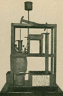
In 1763 James Watt was working as instrument maker at the University of Glasgow when he was assigned the job of repairing a model Newcomen engine and noted how inefficient it was.[6]
In 1765 Watt conceived the idea of equipping the engine with a separate condensation chamber, which he called a "condenser". Because the condenser and the working cylinder were separate, condensation occurred without significant loss of heat from the cylinder. The condenser remained cold and below atmospheric pressure at all times, while the cylinder remained hot at all times.
Steam was drawn from the boiler to the cylinder under the piston. When the piston reached the top of the cylinder, the steam inlet valve closed and the valve controlling the passage to the condenser opened. The condenser being at a lower pressure, drew the steam into the cylinder where it cooled and condensed from water vapor to liquid water, maintaining a partial vacuum in the condenser that was communicated to the space of the cylinder by the connecting passage. External atmospheric pressure then pushed the piston down the cylinder.
The separation of the cylinder and condenser eliminated the loss of heat that occurred when steam was condensed in the working cylinder of a Newcomen engine. This gave the Watt engine greater efficiency than the Newcomen engine, reducing the amount of coal consumed while doing the same amount of work as a Newcomen engine.
In Watt's design, the cold water was injected only into the condensation chamber. This type of condenser is known as a jet condenser. A further improvement to the system of condensation was to dispense with the jet of cold water, and cool the condenser by immersing it in a cold water tank. This type of condenser is known as a separate Condenser.
At each stroke the warm condensate was drawn off from the condenser and sent to a hot well by a vacuum pump, which also helped to evacuate the steam from under the power cylinder. The still-warm condensate was recycled as feedwater for the boiler.
Watt's next improvement to the Newcomen design was to seal the top of the cylinder and surround the cylinder with a jacket. Steam was passed through the jacket before being admitted below the piston, keeping the piston and cylinder warm to prevent condensation within it. Watt did not use high pressure steam because of safety concerns, although he was aware of its potential and included expansive working in his patent of 1782.[1]
These improvements led to the fully developed version of 1776 that actually went into production.[7]
The partnership of Matthew Boulton and James Watt
The separate condenser showed dramatic potential for improvements on the Newcomen engine but Watt was still discouraged by seemingly insurmountable problems before a marketable engine could be perfected. It was only after entering into partnership with Matthew Boulton that such became reality. Watt told Boulton about his ideas on improving the engine, and Boulton, an avid entrepreneur, agreed to fund development of a test engine at Soho, near Birmingham. At last Watt had access to facilities and the practical experience of craftsmen who were soon able to get the first engine working. As fully developed, it used about 75% less fuel than a similar Newcomen one.
In 1775, Watt designed two large engines: one for the Bloomfield Colliery at Tipton, completed in March 1776, and one for John Wilkinson's ironworks at Willey, Shropshire, which was at work the following month. A third engine, at Stratford-le-Bow in east London, was also working that summer.[8]
Watt had tried unsuccessfully for several years to obtain an accurately bored cylinder for his steam engines, and was forced to use hammered iron, which was out of round and caused leakage past the piston. The following quotation is from Roe (1916):
"When [John] Smeaton saw the first engine he reported to the Society of Engineers that 'Neither the tools nor the workmen existed who could manufacture such a complex machine with sufficient precision' "[9]
In 1774 John Wilkinson invented a boring machine in which the shaft that held the cutting tool was supported on both ends and extended through the cylinder, unlike the cantilevered borers then in use. Boulton wrote in 1776 that "Mr. Wilkinson has bored us several cylinders almost without error; that of 50 inches diameter, which we have put up at Tipton, does not err on the thickness of an old shilling in any part".[9]
Boulton and Watt's practice was to help mine-owners and other customers to build engines, supplying men to erect them and some specialised parts. However, their main profit from their patent was derived from charging a licence fee to the engine owners, based on the cost of the fuel they saved. The greater fuel efficiency of their engines meant that they were most attractive in areas where fuel was expensive, particularly Cornwall, for which three engines were ordered in 1777, for the Wheal Busy, Ting Tang, and Chacewater mines.[10]
Later improvements

The first Watt engines were atmospheric pressure engines, like the Newcomen engine but with the condensation taking place separate from the cylinder. Driving the engines using both low pressure steam and a partial vacuum raised the possibility of reciprocating engine development.[11] An arrangement of valves could alternately admit low pressure steam to the cylinder and then connect with the condenser. Consequently, the direction of the power stroke might be reversed, making it easier to obtain rotary motion. Additional benefits of the double acting engine were increased efficiency, higher speed (greater power) and more regular motion.
Before the development of the double acting piston, the linkage to the beam and the piston rod had been by means of a chain, which meant that power could only be applied in one direction, by pulling. This was effective in engines that were used for pumping water, but the double action of the piston meant that it could push as well as pull. This was not possible as long as the beam and the rod were connected by a chain. Furthermore, it was not possible to connect the piston rod of the sealed cylinder directly to the beam, because while the rod moved vertically in a straight line, the beam was pivoted at its centre, with each side inscribing an arc. To bridge the conflicting actions of the beam and the piston, Watt developed his parallel motion. This masterpiece of engineering uses a four bar linkage coupled with a pantograph to produce the required straight line motion much more cheaply than if he had used a slider type of linkage. He was very proud of his solution.
Having the beam connected to the piston shaft by a means that applied force alternately in both directions also meant that it was possible to use the motion of the beam to turn a wheel. The most simple solution to transforming the action of the beam into a rotating motion was to connect the beam to a wheel by a crank, but because another party had patent rights on the use of the crank, Watt was obliged to come up with another solution.[13] He adopted the epicyclic sun and planet gear system suggested by an employee William Murdoch, only later reverting, once the patent rights had expired, to the more familiar crank seen on most engines today.[14] The main wheel attached to the crank was large and heavy, serving as a flywheel which, once set in motion, by its momentum maintained a constant power and smoothed the action of the alternating strokes. To its rotating central shaft, belts and gears could be attached to drive a great variety of machinery.
Because factory machinery needed to operate at a constant speed, Watt linked a steam regulator valve to a centrifugal governor which he adapted from those used to automatically control the speed of windmills.[15]
These improvements allowed the steam engine to replace the water wheel and horses as the main sources of power for British industry, thereby freeing it from geographical constraints and becoming one of the main drivers in the Industrial Revolution.
Watt was also concerned with fundamental research on the functioning of the steam engine. His most notable measuring device, still in use today, is the Watt indicator incorporating a manometer to measure steam pressure within the cylinder according to the position of the piston, enabling a diagram to be produced representing the pressure of the steam as a function of its volume throughout the cycle.
Preserved Watt engines
The oldest surviving Watt engine is Old Bess of 1777, now in the Science Museum, London. The oldest working engine in the world is the Smethwick Engine, brought into service in May 1779 and now at Thinktank in Birmingham (formerly at the now defunct Museum of Science and Industry, Birmingham). The oldest still in its original engine house and still capable of doing the job for which it was installed is the 1812 Boulton and Watt engine at the Crofton Pumping Station. This was used to pump water for the Kennet and Avon Canal; on certain weekends throughout the year the modern pumps are switched off and the two steam engines at Crofton still perform this function. The oldest extant rotative steam engine, the Whitbread Engine (from 1785, the third rotative engine ever built), is located in the Powerhouse Museum in Sydney, Australia. A Boulton-Watt engine of 1788 may be found in the Science Museum, London.,[16] while an 1817 blowing engine, formerly used at the Netherton ironworks of M W Grazebrook now decorates Dartmouth Circus, a traffic island at the start of the A38(M) motorway in Birmingham.
The Henry Ford Museum in Dearborn, Michigan houses a Watt rotative engine manufactured in 1788 by Charles Summerfield. This is a full-scale working Boulton-Watt engine. The American industrialist Henry Ford moved the engine to Dearborn around 1930.
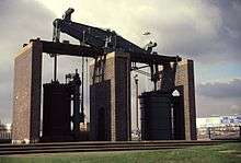 The 1817 engine in Birmingham, England
 Watt rotative engine at The Henry Ford Museum
See also
- Carnot cycle
- Corliss steam engine
- Heat engine
- Thermodynamics
- Preserved beam engines
- Ivan Polzunov made a powerful non-condensing steam engine in 1776, but died before he could mass-produce it
References
- 1 2 Dickinson, Henry Winram (1939). A Short History of the Steam Engine. Cambridge University Press. p. 87. ISBN 978-1-108-01228-7.
- ↑ Rosen, William (2012). The Most Powerful Idea in the World: A Story of Steam, Industry and Invention. University of Chicago Press. p. 137. ISBN 978-0226726342.
- ↑ Landes, David S. (1969). The Unbound Prometheus: Technological Change and Industrial Development in Western Europe from 1750 to the Present. Cambridge, New York: Press Syndicate of the University of Cambridge. ISBN 0-521-09418-6.
- ↑ Ayres, Robert (1989). "Technological Transformations and Long Waves" (PDF): 13.
- 1 2 Rosen year-2012
- ↑ "Model Newcomen Engine, repaired by James Watt". University of Glasgow Hunterian Museum & Art Gallery. Retrieved 1 July 2014.
- ↑ Hulse David K (1999): "The early development of the steam engine"; TEE Publishing, Leamington Spa, U.K., ISBN, 85761 107 1 p. 127 et seq.
- ↑ R. L. Hills, James Watt: II The Years of Toil, 1775–1785 (Landmark, Ashbourne, 2005), 58–65.
- 1 2 Roe, Joseph Wickham (1916), English and American Tool Builders, New Haven, Connecticut: Yale University Press, LCCN 16011753. Reprinted by McGraw-Hill, New York and London, 1926 (LCCN 27-24075); and by Lindsay Publications, Inc., Bradley, Illinois, (ISBN 978-0-917914-73-7).
- ↑ Hills, 96–105.
- ↑ Hulse David K (2001): "The development of rotary motion by the steam power"; TEE Publishing, Leamington Spa, U.K., ISBN, 1 85761 119 5 : p 58 et seq.
- ↑ from 3rd edition Britannica 1797
- ↑ Jamew Wat: Monopolist
- ↑ Rosen year-2012, pp. 176–7
- ↑ Thurston, Robert H. (1875). A History of the Growth of the Steam-Engine. D. Appleton & Co. p. 116. This is the first edition. Modern paperback editions are available.
- ↑ "Rotative steam engine by Boulton and Watt, 1788". Science Museum.
External links
| Wikimedia Commons has media related to Watt steam engines. |
- Watt atmospheric engine – Michigan State University, Chemical Engineering
- Watt's 'perfect engine' – excerpts from Transactions of the Newcomen Society.
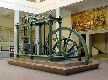
- Boulton & Watt engine at the National Museum of Scotland
- Boulton and Watt Steam Engine at the Powerhouse Museum, Sydney