Induction motor

An asynchronous motor type of an induction motor is an AC electric motor in which the electric current in the rotor needed to produce torque is obtained by electromagnetic induction from the magnetic field of the stator winding. An induction motor can therefore be made without electrical connections to the rotor as are found in universal, DC and synchronous motors. An asynchronous motor's rotor can be either wound type or squirrel-cage type.
Three-phase squirrel-cage asynchronous motors are widely used in industrial drives because they are rugged, reliable and economical. Single-phase induction motors are used extensively for smaller loads, such as household appliances like fans. Although traditionally used in fixed-speed service, induction motors are increasingly being used with variable-frequency drives (VFDs) in variable-speed service. VFDs offer especially important energy savings opportunities for existing and prospective induction motors in variable-torque centrifugal fan, pump and compressor load applications. Squirrel cage induction motors are very widely used in both fixed-speed and variable-frequency drive (VFD) applications. Variable voltage and variable frequency drives are also used in variable-speed service.
.JPG)
History

In 1824, the French physicist François Arago formulated the existence of rotating magnetic fields, termed Arago's rotations, which, by manually turning switches on and off, Walter Baily demonstrated in 1879 as in effect the first primitive induction motor.[1][2][3][4] The first alternating-current commutatorless induction motors have been independently invented by Galileo Ferraris and Nikola Tesla, a working motor model having been demonstrated by the former in 1885 and by the latter in 1887. Tesla applied for U.S. patents in October and November 1887 and was granted some of these patents in May 1888. In April 1888, the Royal Academy of Science of Turin published Ferraris's research on his AC polyphase motor detailing the foundations of motor operation.[4][5] In May 1888 Tesla presented the technical paper A New System for Alternating Current Motors and Transformers to the American Institute of Electrical Engineers (AIEE)[6][7][8][9][10] describing three four-stator-pole motor types: one with a four-pole rotor forming a non-self-starting reluctance motor, another with a wound rotor forming a self-starting induction motor, and the third a true synchronous motor with separately excited DC supply to rotor winding. George Westinghouse, who was developing an alternating current power system at that time, licensed Tesla’s patents in 1888 and purchased a US patent option on Ferraris' induction motor concept.[11] Tesla was also employed for one year as a consultant. Westinghouse employee C. F. Scott was assigned to assist Tesla and later took over development of the induction motor at Westinghouse.[6][12][13][14] Steadfast in his promotion of three-phase development, Mikhail Dolivo-Dobrovolsky invented the cage-rotor induction motor in 1889 and the three-limb transformer in 1890.[15][16] Furthermore, he claimed that Tesla's motor was not practical because of the two-phase pulsations.[17] Although Westinghouse achieved its first practical induction motor in 1892 and developed a line of polyphase 60 hertz induction motors in 1893, these early Westinghouse motors were two-phase motors with wound rotors until B. G. Lamme developed a rotating bar winding rotor.[6] The General Electric Company (GE) began developing three-phase induction motors in 1891.[6] By 1896, General Electric and Westinghouse signed a cross-licensing agreement for the bar-winding-rotor design, later called the squirrel-cage rotor.[6] Arthur E. Kennelly was the first to bring out full significance of the letter "i" (the square root of minus one) to designate the 90-degree rotation operator in complex number analysis of AC problems.[18] GE's Charles Proteus Steinmetz greatly developed the application of AC complex quantities by including terms now commonly known as the induction motor's Steinmetz equivalent circuit.[6][19][20][21] Induction motor improvements flowing from these inventions and innovations were such that a 100-horsepower induction motor currently has the same mounting dimensions as a 7.5-horsepower motor in 1897.[6]
Principles of operation

In both induction and synchronous motors, the AC power supplied to the motor's stator creates a magnetic field that rotates in time with the AC oscillations. Whereas a synchronous motor's rotor turns at the same rate as the stator field, an induction motor's rotor rotates at a slower speed than the stator field. The induction motor stator's magnetic field is therefore changing or rotating relative to the rotor. This induces an opposing current in the induction motor's rotor, in effect the motor's secondary winding, when the latter is short-circuited or closed through an external impedance.[22] The rotating magnetic flux induces currents in the windings of the rotor;[23] in a manner similar to currents induced in a transformer's secondary winding(s). The currents in the rotor windings in turn create magnetic fields in the rotor that react against the stator field. Due to Lenz's Law, the direction of the magnetic field created will be such as to oppose the change in current through the rotor windings. The cause of induced current in the rotor windings is the rotating stator magnetic field, so to oppose the change in rotor-winding currents the rotor will start to rotate in the direction of the rotating stator magnetic field. The rotor accelerates until the magnitude of induced rotor current and torque balances the applied load. Since rotation at synchronous speed would result in no induced rotor current, an induction motor always operates slower than synchronous speed. The difference, or "slip," between actual and synchronous speed varies from about 0.5 to 5.0% for standard Design B torque curve induction motors.[24] The induction machine's essential character is that it is created solely by induction instead of being separately excited as in synchronous or DC machines or being self-magnetized as in permanent magnet motors.[22]
For rotor currents to be induced, the speed of the physical rotor must be lower than that of the stator's rotating magnetic field (); otherwise the magnetic field would not be moving relative to the rotor conductors and no currents would be induced. As the speed of the rotor drops below synchronous speed, the rotation rate of the magnetic field in the rotor increases, inducing more current in the windings and creating more torque. The ratio between the rotation rate of the magnetic field induced in the rotor and the rotation rate of the stator's rotating field is called slip. Under load, the speed drops and the slip increases enough to create sufficient torque to turn the load. For this reason, induction motors are sometimes referred to as asynchronous motors.[25] An induction motor can be used as an induction generator, or it can be unrolled to form a linear induction motor which can directly generate linear motion.

Synchronous speed
An AC motor's synchronous speed, , is the rotation rate of the stator's magnetic field,
- ,

where is the motor supply's frequency, where is the number of magnetic poles and where and have identical units. For in unit Hertz and in RPM, the formula becomes


For example, for a four-pole three-phase motor, equals 4, thus which equals 25 Hz (1,500 RPM) and 30 Hz (1,800 RPM) respectively for 50 Hz and 60 Hz supply systems.

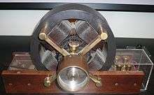
Note that , "the number of poles" is a notional number determined by analogy to a single-phase machine, the simplest type of which has 2 poles of opposite magnetic polarity set at 180 degrees with respect to each other. The simplest three-phase machine has three pole pairs (total 6 stator poles), each pair connected to one of the phases of the 3-phase supply (red, green, blue), and arranged evenly around the stator. In a 4-pole 3-phase machine (4 pole-pairs, so for three phases it is 4 x 3 = 12 poles) there are 12 poles set at 30 degree intervals. This is illustrated above right. The illustration on the left is of a 2-pole machine (2 pole-pairs, so for three phases it is 2 x 3 = 6 poles).
Slip

Slip, , is defined as the difference between synchronous speed and operating speed, at the same frequency, expressed in rpm or in percent or ratio of synchronous speed. Thus


where is stator electrical speed, is rotor mechanical speed.[28][29] Slip, which varies from zero at synchronous speed and 1 when the rotor is at rest, determines the motor's torque. Since the short-circuited rotor windings have small resistance, a small slip induces a large current in the rotor and produces large torque.[30] At full rated load, slip varies from more than 5% for small or special purpose motors to less than 1% for large motors.[31] These speed variations can cause load-sharing problems when differently sized motors are mechanically connected.[31] Various methods are available to reduce slip, VFDs often offering the best solution.[31]

Torque
Standard torque

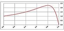
The typical speed-torque relationship of a standard NEMA Design B polyphase induction motor is as shown in the curve at right. Suitable for most low performance loads such as centrifugal pumps and fans, Design B motors are constrained by the following typical torque ranges:[24][lower-alpha 1]
- Breakdown torque (peak torque), 175-300 percent of rated torque
- Locked-rotor torque (torque at 100% slip), 75-275 percent of rated torque
- Pull-up torque, 65-190 percent of rated torque.
Over a motor's normal load range, the torque's slope is approximately linear or proportional to slip because the value of rotor resistance divided by slip, , dominates torque in linear manner.[32] As load increases above rated load, stator and rotor leakage reactance factors gradually become more significant in relation to such that torque gradually curves towards breakdown torque. As the load torque increases beyond breakdown torque the motor stalls.

Starting
There are three basic types of competing small induction motors: single-phase split-phase, single-phase shaded-pole types, and polyphase motors.
Although polyphase motors are inherently self-starting, their starting and pull-up torque design limits must be high enough to overcome actual load conditions.
In two-pole single-phase motors, the torque goes to zero at 100% slip (zero speed), so these require alterations to the stator such as shaded-poles to provide starting torque. A single phase induction motor requires separate starting circuitry to provide a rotating field to the motor. The normal running windings within such a single-phase motor can cause the rotor to turn in either direction, so the starting circuit determines the operating direction.
In certain smaller single-phase motors, starting is done by means of a shaded pole with a copper wire turn around part of the pole. The current induced in this turn lags behind the supply current, creating a delayed magnetic field around the shaded part of the pole face. This imparts sufficient rotational field energy to start the motor. These motors are typically used in applications such as desk fans and record players, as the required starting torque is low, and the low efficiency is tolerable relative to the reduced cost of the motor and starting method compared to other AC motor designs.
Larger single phase motors are split-phase motors and have a second stator winding fed with out-of-phase current; such currents may be created by feeding the winding through a capacitor or having it receive different values of inductance and resistance from the main winding. In capacitor-start designs, the second winding is disconnected once the motor is up to speed, usually either by a centrifugal switch acting on weights on the motor shaft or a thermistor which heats up and increases its resistance, reducing the current through the second winding to an insignificant level. The capacitor-run designs keep the second winding on when running, improving torque. A resistance start design uses a starter inserted in series with the startup winding, creating reactance.
Self-starting polyphase induction motors produce torque even at standstill. Available squirrel cage induction motor starting methods include direct-on-line starting, reduced-voltage reactor or auto-transformer starting, star-delta starting or, increasingly, new solid-state soft assemblies and, of course, VFDs.[33]
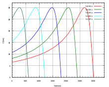
Polyphase motors have rotor bars shaped to give different speed-torque characteristics. The current distribution within the rotor bars varies depending on the frequency of the induced current. At standstill, the rotor current is the same frequency as the stator current, and tends to travel at the outermost parts of the cage rotor bars (by skin effect). The different bar shapes can give usefully different speed-torque characteristics as well as some control over the inrush current at startup.
In wound rotor motors, rotor circuit connection through slip rings to external resistances allows change of speed-torque characteristics for acceleration control and speed control purposes.
Speed control
Before the development of semiconductor power electronics, it was difficult to vary the frequency, and cage induction motors were mainly used in fixed speed applications. Applications such as electric overhead cranes used DC drives or wound rotor motors (WRIM) with slip rings for rotor circuit connection to variable external resistance allowing considerable range of speed control. However, resistor losses associated with low speed operation of WRIMs is a major cost disadvantage, especially for constant loads.[34] Large slip ring motor drives, termed slip energy recovery systems, some still in use, recover energy from the rotor circuit, rectify it, and return it to the power system using a VFD. In many industrial variable-speed applications, DC and WRIM drives are being displaced by VFD-fed cage induction motors. The most common efficient way to control asynchronous motor speed of many loads is with VFDs. Barriers to adoption of VFDs due to cost and reliability considerations have been reduced considerably over the past three decades such that it is estimated that drive technology is adopted in as many as 30-40% of all newly installed motors.[35]
Construction

The stator of an induction motor consists of poles carrying supply current to induce a magnetic field that penetrates the rotor. To optimize the distribution of the magnetic field, windings are distributed in slots around the stator, with the magnetic field having the same number of north and south poles. Induction motors are most commonly run on single-phase or three-phase power, but two-phase motors exist; in theory, induction motors can have any number of phases. Many single-phase motors having two windings can be viewed as two-phase motors, since a capacitor is used to generate a second power phase 90° from the single-phase supply and feeds it to the second motor winding. Single-phase motors require some mechanism to produce a rotating field on startup. Cage induction motor rotor's conductor bars are typically skewed to reduce noise.
Rotation reversal
The method of changing the direction of rotation of an induction motor depends on whether it is a three-phase or single-phase machine. In the case of three phase, reversal is carried out by swapping connection of any two phase conductors. In a single-phase split-phase motor, it is achieved by changing the connection between the primary winding and the start circuit. Single-phase split-phase motors that are designed for specific applications may have the connection between the primary winding and the start circuit connected internally so that the rotation cannot be changed. Also, single-phase shaded-pole motors have a fixed rotation, and the direction cannot be changed (except by disassembly of the motor and rotating the stator to face opposite relative to the original rotor direction).
Power factor
The power factor of induction motors varies with load, typically from around 0.85 or 0.90 at full load to as low as 0.12 at no-load,[33] due to stator and rotor leakage and magnetizing reactances.[36] Power factor can be improved by connecting capacitors either on an individual motor basis or, by preference, on a common bus covering several motors. For economic and other considerations, power systems are rarely power factor corrected to unity power factor.[37] Power capacitor application with harmonic currents requires power system analysis to avoid harmonic resonance between capacitors and transformer and circuit reactances.[38] Common bus power factor correction is recommended to minimize resonant risk and to simplify power system analysis.[38]
Efficiency
(See also Energy savings)
Full load motor efficiency varies from about 85% to 97%, related motor losses being broken down roughly as follows:[39]
- Friction and windage, 5% – 15%
- Iron or core losses, 15% – 25%
- Stator losses, 25% – 40%
- Rotor losses, 15% – 25%
- Stray load losses, 10% – 20%.
Various regulatory authorities in many countries have introduced and implemented legislation to encourage the manufacture and use of higher efficiency electric motors. There is existing and forthcoming legislation regarding the future mandatory use of premium-efficiency induction-type motors in defined equipment. For more information, see: Premium efficiency.
Frame Sizes
Standardized frame sizes throughout the industry result in common dimensions for shaft diameter, shaft height, shaft length, bolt hole spacing and location. The lower the speed the larger the frame. Motors with fans, including TOTALLY ENCLOSED FAN COOLED(TEFC) motors can be a smaller frame size than OPEN DRIP PROOF (ODP) motors.[40]
Steinmetz equivalent circuit
Many useful motor relationships between time, current, voltage, speed, power factor and torque can be obtained from analysis of the Steinmetz equivalent circuit (also termed T-equivalent circuit or IEEE recommended equivalent circuit), a mathematical model used to describe how an induction motor's electrical input is transformed into useful mechanical energy output. The equivalent circuit is a single-phase representation of a multiphase induction motor that is valid in steady-state balanced-load conditions.
The Steinmetz equivalent circuit is expressed simply in terms of the following components:
- Stator resistance and leakage reactance (, ).
- Rotor resistance, leakage reactance, and slip (, or , , and ).
- Magnetizing reactance ().


Paraphrasing from Alger in Knowlton, an induction motor is simply an electrical transformer the magnetic circuit of which is separated by an air gap between the stator winding and the moving rotor winding.[22] The equivalent circuit can accordingly be shown either with equivalent circuit components of respective windings separated by an ideal transformer or with rotor components referred to the stator side as shown in the following circuit and associated equation and parameter definition tables.[33][37][41][42][43][44]

| Circuit Parameter Definitions | ||
|---|---|---|
| Units | ||
| stator synchronous frequency | Hz | |
| rotor speed in revolutions per minute | rpm | |
| synchronous speed in revolutions per minute | rpm | |
| stator or primary current | A | |
| rotor or secondary current referred to stator side | A | |
| magnetizing current | A | |
| imaginary number, or 90° rotation, operator | ||
| Thévenin reactance factor | ||
| number of motor phases | ||
| number of motor poles | ||
| electromechanical power | W or hp | |
| air gap power | W | |
| rotor copper losses | W | |
| input power | W | |
| core loss | W | |
| friction and windage loss | W | |
| running light watts input | W | |
| stray-load loss | W | |
| stator or primary resistance and leakage reactance | Ω | |
| rotor or secondary resistance & leakage reactance referred to the stator side | Ω | |
| resistance & leakage reactance at motor input | Ω | |
| Thévenin equivalent resistance & leakage reactance combining and | Ω | |
| slip | ||
| electromagnetic torque | Nm or ft.-lb. | |
| breakdown torque | Nm or ft.-lb. | |
| impressed stator phase voltage | V | |
| magnetizing reactance | Ω | |
| Ω | ||
| stator or primary impedance | Ω | |
| rotor or secondary impedance referred to the primary | Ω | |
| impedance at motor stator or primary input | Ω | |
| combined rotor or secondary and magnetizing impedance | Ω | |
| Thévenin equivalent circuit impedance, | Ω | |
| rotor speed | rad/s | |
| synchronous speed | rad/s | |
| mho | ||
| Ω | ||


The following rule-of-thumb approximations apply to the circuit:[44][45][46]
- Maximum current happens under locked rotor current (LRC) conditions and is somewhat less than , with LRC typically ranging between 6 and 7 times rated current for standard Design B motors.[24]
- Breakdown torque happens when and such that and thus, with constant voltage input, a low-slip induction motor's percent-rated maximum torque is about half its percent-rated LRC.
- The relative stator to rotor leakage reactance of standard Design B cage induction motors is[47]


- .

- Neglecting stator resistance, an induction motor's torque curve reduces to the Kloss equation[48]
- , where is slip at .


| Basic Electrical Equations | ||
|---|---|---|
|
Motor input equivalent impedance Stator current Rotor current referred to the stator side in terms of stator current | ||


| Power Equations | ||
|---|---|---|
|
From Steinmetz equivalent circuit, we have That is, air gap power is equal to electromechanical power output plus rotor copper losses Expressing electromechanical power output in terms of rotor speed
Expressing in ft.-lb.:
| ||


| Torque Equations | ||
|---|---|---|
In order to be able to express directly in terms of , IEEE recommends that and be converted to the Thévenin equivalent circuit  IEEE recommended Thévenin equivalent circuit where Since and , and letting
For low values of slip:
For high values of slip
For maximum or breakdown torque, which is independent of rotor resistance
Corresponding slip at maximum or breakdown torque is In foot-pound units
| ||


Linear induction motor
Linear induction motors, that work on same general principles as rotary induction motors and are frequently three-phase, are designed to produce straight line motion. Uses include magnetic levitation, linear propulsion, linear actuators, and liquid metal pumping.[49]
See also
- AC motor
- Circle diagram
- Induction generator
- Premium efficiency
- Copper in energy efficient motors
- Induction motors modelling in ABC frame of reference
- Variable refrigerant flow
Notes
- ↑ NEMA MG-1 defines a) breakdown torque as the maximum torque developed by the motor with rated voltage applied at rated frequency without an abrupt drop in speed, b) locked-rotor torque as the minimum torque developed by the motor at rest with rated voltage applied at rated frequency, and c) pull-up torque as the minimum torque developed by the motor during the period of acceleration from rest to the speed at which breakdown torque occurs.
References
- ↑ Babbage, C.; Herschel, J. F. W. (Jan 1825). "Account of the Repetition of M. Arago's Experiments on the Magnetism Manifested by Various Substances during the Act of Rotation". Philosophical Transactions of the Royal Society. 115 (0): 467–496. doi:10.1098/rstl.1825.0023. Retrieved 2 December 2012.
- ↑ Thompson, Silvanus Phillips (1895). Polyphase Electric Currents and Alternate-Current Motors (1st ed.). London: E. & F.N. Spon. p. 261. Retrieved 2 December 2012.
- ↑ Baily, Walter (June 28, 1879). "A Mode of producing Arago's Rotation". Philosophical magazine: A journal of theoretical, experimental and applied physics. Taylor & Francis.
- 1 2 Vučković, Vladan (November 2006). "Interpretation of a Discovery" (PDF). The Serbian Journal of Electrical Engineers. 3 (2). Retrieved 10 February 2013.
- ↑ Ferraris, G. (1888). "Atti della Reale Academia delle Science di Torino". Atti della R. Academia delle Science di Torino. XXIII: 360–375.
- 1 2 3 4 5 6 7 Alger, P.L.; Arnold, R.E. (1976). "The History of Induction Motors in America". Proceedings of the IEEE. 64 (9): 1380–1383. doi:10.1109/PROC.1976.10329.
- ↑ Froehlich, Fritz E. Editor-in-Chief; Allen Kent Co-Editor (1992). The Froehlich/Kent Encyclopedia of Telecommunications: Volume 17 - Television Technology to Wire Antennas (First ed.). New York: Marcel Dekker, Inc. p. 36. ISBN 0-8247-2902-1. Retrieved 2 December 2012.
- ↑ The Electrical Engineer (21 Sep 1888). . . . a new application of the alternating current in the production of rotary motion was made known almost simultaneously by two experimenters, Nikola Tesla and Galileo Ferraris, and the subject has attracted general attention from the fact that no commutator or connection of any kind with the armature was required. . . . Volume II. London: Charles & Co. p. 239.
- ↑ Ferraris, Galileo (1885). "Electromagnetic Rotation with an Alternating Current". Electrician. 36: 360–375.
- ↑ Tesla, Nikola; AIEE Trans. (1888). "A New System for Alternating Current Motors and Transformers". AIEE. 5: 308–324. Retrieved 17 December 2012.
- ↑ Jill Jonnes, Empires of Light: Edison, Tesla, Westinghouse, and the Race to Electrify the World, Edison Declares War
- ↑ Electrical World, Volume 78, No 7. page 340
- ↑ Klooster, John W. (30 July 2009). Icons of Invention the Makers of the Modern World from Gutenberg to Gates. Santa Barbara: ABC-CLIO. p. 305. ISBN 978-0-313-34744-3. Retrieved 10 September 2012.
- ↑ Day, Lance (1996). McNeil, Ian, ed. Biographical Dictionary of the History of Technology. London: Routledge. p. 1204. ISBN 0-203-02829-5. Retrieved 2 December 2012.
- ↑ Hubbell, M.W. (2011). The Fundamentals of Nuclear Power Generation Questions & Answers. Authorhouse. p. 27. ISBN 978-1463424411.
- ↑ VDE Committee History of Electrical Engineering IEEE German Chapter (January 2012). "150th Birthday of Michael von Dolivo-Dobrowolsky Colloquium". 13. Retrieved 10 February 2013.
- ↑ Dolivo-Dobrowolsky, M. (1891). ETZ. 12: 149, 161. Missing or empty
|title=(help) - ↑ Kennelly, A. E. (Jan 1893). "Impedance". Transactions of the American Institute of Electrical Engineers. X: 172–232. doi:10.1109/T-AIEE.1893.4768008.
- ↑ Steinmetz, Charles Porteus (1897). "The Alternating Current Induction Motor". AIEE Trans. XIV (1): 183–217. Retrieved 18 December 2012.
- ↑ Banihaschemi, Abdolmajid (1973). Determination of the Losses in Induction Machines Due to Harmonics (PDF). Fredericton, N.B.: University of New Brunswick. pp. 1, 5–8.
- ↑ Steinmetz, Charles Proteus; Berg, Ernst J. (1897). Theory and Calculation of Alternating Current Phenomena. McGraw Publishing Company.
- 1 2 3 Alger, Philip L.; et al. (1949). "'Induction Machines' sub-section of Sec. 7 - Alternating-Current Generators and Motors". In Knowlton, A.E. Standard Handbook for Electrical Engineers (8th ed.). McGraw-Hill. p. 705.
- ↑ "AC Motors". NSW HSC Online - Charles Sturt University. Retrieved 2 December 2012.
- 1 2 3 NEMA MG-1 2007 Condensed (2008). Information Guide for General Purpose Industrial AC Small and Medium Squirrel-Cage Induction Motor Standards. Rosslyn, Virginia US: NEMA. p. 29 (Table 11). Retrieved 2 December 2012.
- ↑ "Induction (Asynchronous) Motors" (PDF). Mississippi State University Dept of Electrical and Computer Engineering, Course ECE 3183, 'Electrical Engineering Systems for non-ECE majors'. Retrieved 2 December 2012.
- ↑ "Induction Motors". electricmotors.machinedesign.com. Penton Media, Inc. Archived from the original on 2007-11-16. Retrieved 2016-04-12.
- ↑ "Motor Formulas". elec-toolbox.com. Retrieved 1 January 2013.
- ↑ Srivastava, Avinash; Kumar, Ravi. "Torque Slip Characteristics of Induction Motor". Course notes. Malnad College Of Engineering.
- ↑ NEMA Standards Publication (2007). Application Guide for AC Adjustable Speed Drive Systems. Rosslyn, Virginia US: NEMA. p. 6. Retrieved 2 December 2012.
- ↑ Herman, Stephen L. (2011). Alternating Current Fundamentals (8th ed.). US: Cengage Learning. pp. 529–536. ISBN 1-111-03913-5.
- 1 2 3 Peltola, Mauri. "AC Induction Motor Slip". Plantservices.com. Retrieved 18 December 2012.
- ↑ Keljik, Jeffrey (2009). "Chapter 12 - The Three-Phase, Squirrel-Cage Induction Motor". Electricity 4 : AC/DC Motors, Controls, and Maintenance (9th ed.). Clifton Park, NY: Delmar, Cengage Learning. pp. 112–115. ISBN 1-4354-0031-3.
- 1 2 3 Liang, Xiaodong; Ilochonwu, Obinna (Jan 2011). "Induction Motor Starting in Practical Industrial Applications" (PDF). IEEE Transactions on Industry Applications. 47 (1): 271–280. doi:10.1109/TIA.2010.2090848. Retrieved 4 December 2012.
- ↑ Jamil Asghar, M.S. (2003). "Speed control of wound rotor induction motors by AC regulator based optimum voltage control". Power Electronics and Drive Systems, 2003. The Fifth International Conference on. 2: 1037–1040. doi:10.1109/PEDS.2003.1283113.
- ↑ Lendenmann, Heinz; et al. "Motoring Ahead" (PDF). Retrieved Apr 18, 2012.
- ↑ Fink, D.G.; Beaty, H.W. (1978). Standard Handbook for Electrical Engineers (11th ed.). McGraw-Hill. pp. 20–28 thru 20–29.
- 1 2 Jordan, Howard E. (1994). Energy-Efficient Electric Motors and their Applications (2nd ed.). New York: Plenum Press. ISBN 0-306-44698-7.
- 1 2 NEMA MG-1, p. 19
- ↑ U.S. DOE (2008). "Improving Motor and Drive System Performance: A Sourcebook for Industry" (PDF). p. 27. Retrieved 31 December 2012.
- ↑ ABB Group (Baldor Electric Company) (2016). "SPECIFIER GUIDE" (PDF). p. 6. Retrieved 4 October 2016.
- ↑ Hubert, Charles I. (2002). Electric Machines : Theory, Operation, Applications, Adjustment, and Control (2nd ed.). Upper Saddle River, N.J.: Prentice Hall. pp. Chapter 4. ISBN 0130612103.
- ↑ Beaty, H. Wayne (Ed.) (2006). "Section 5 - Three-Phase Induction Motors by Hashem Oraee" (PDF). Handbook of Electric Power Calculations (3rd ed.). New York: McGraw-Hill. ISBN 0-07-136298-3.
- ↑ Knight, Andy. "Three-Phase Induction Machines". Hosted by University of Alberta. Retrieved 21 December 2012.
- 1 2 IEEE 112 (2004). IEEE Standard Test Procedure for Polyphase Induction Motors and Generators. New York, N.Y.: IEEE. ISBN 0-7381-3978-5.
- ↑ Alger (1949), p. 711
- 1 2 3 4 5 Özyurt, Ç.H. (2005). Parameter and Speed Estimation of Induction Motors from Manufacturers Data and Measurements (PDF). Middle East Technical University. pp. 33–34.
- ↑ Knight, Andy. "Determining Induction Machine Parameters". Hosted by University of Alberta. Retrieved 31 December 2012.
- ↑ Hameyer, Kay (2001). "Electrical Machine I: Basics, Design, Function, Operation" (PDF). RWTH Aachen University Institute of Electrical Machines. Retrieved 11 January 2013.page=133
- ↑ Bulletin of the Atomic Scientists. Educational Foundation for Atomic Science. 6 June 1973. Retrieved 8 August 2012.
Classical sources
- Bailey, Benjamin Franklin (1911). The Induction Motor. McGraw-Hill.
- Behrend, Bernhard Arthur (1901). The Induction Motor: A Short Treatise on its Theory and Design, With Numerous Experimental Data and Diagrams. McGraw Publishing Company / Electrical World and Engineer.
- Boy de la Tour, Henri (1906). The Induction Motor: Its Theory and Design, Set Forth By a Practical Method of Calculation. Translated Cyprien Odilon Mailloux. McGraw Pub. Co.
External links
| Wikimedia Commons has media related to Induction motors. |
- An induction motor drawing
- Rotating magnetic fields: interactive, (Italian)
- Construct your squirrel cage induction motor, using povray
- Induction motor topics from Hyperphysics website hosted by C.R. Nave, GSU Physics and Astronomy Dept.
- Torques in Electrical Induction Motors on Engineering ToolBox
