Vector control (motor)
Vector control, also called field-oriented control (FOC), is a variable-frequency drive (VFD) control method in which the stator currents of a three-phase AC electric motor are identified as two orthogonal components that can be visualized with a vector. One component defines the magnetic flux of the motor, the other the torque. The control system of the drive calculates the corresponding current component references from the flux and torque references given by the drive's speed control. Typically proportional-integral (PI) controllers are used to keep the measured current components at their reference values. The pulse-width modulation of the variable-frequency drive defines the transistor switching according to the stator voltage references that are the output of the PI current controllers.[1]
FOC is used to control AC synchronous and induction motors.[2] It was originally developed for high-performance motor applications that are required to operate smoothly over the full speed range, generate full torque at zero speed, and have high dynamic performance including fast acceleration and deceleration. However, it is becoming increasingly attractive for lower performance applications as well due to FOC's motor size, cost and power consumption reduction superiority.[3][4] It is expected that with increasing computational power of the microprocessors it will eventually nearly universally displace single-variable scalar volts-per-Hertz (V/f) control.[5][6]
Development history
Technische Universität Darmstadt's K. Hasse and Siemens' F. Blaschke pioneered vector control of AC motors starting in 1968 and in the early 1970s. Hasse in terms of proposing indirect vector control, Blaschke in terms of proposing direct vector control.[7][8] Technical University Braunschweig's Werner Leonhard further developed FOC techniques and was instrumental in opening up opportunities for AC drives to be a competitive alternative to DC drives.[9][10]
Yet it was not until after the commercialization of microprocessors, that is in the early 1980s, that general purpose AC drives became available.[11][12] Barriers to use FOC for AC drive applications included higher cost and complexity and lower maintainability compared to DC drives, FOC having until then required many electronic components in terms of sensors, amplifiers and so on.[13]
The Park transformation has long been widely used in the analysis and study of synchronous and induction machines. The transformation is by far the single most important concept needed for an understanding of how FOC works, the concept having been first conceptualized in a 1929 paper authored by Robert H. Park.[14] Park's paper was ranked second most important in terms of impact from among all power engineering related papers ever published in the twentieth century. The novelty of Park's work involves his ability to transform any related machine's linear differential equation set from one with time varying coefficients to another with time invariant coefficients.[15]
Technical overview
Overview of key competing VFD control platforms:
| VFD, with sensor or sensorless |
| |||||||||||||||||||||||||||
| |
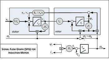
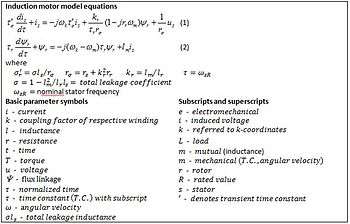
While the analysis of AC drive controls can be technically quite involved ("See also" section), such analysis invariably starts with modeling of the drive-motor circuit involved along the lines of accompanying signal flow graph and equations.[19]
In vector control, an AC induction or synchronous motor is controlled under all operating conditions like a separately excited DC motor.[21] That is, the AC motor behaves like a DC motor in which the field flux linkage and armature flux linkage created by the respective field and armature (or torque component) currents are orthogonally aligned such that, when torque is controlled, the field flux linkage is not affected, hence enabling dynamic torque response.
Vector control accordingly generates a three-phase PWM motor voltage output derived from a complex voltage vector to control a complex current vector derived from motor's three-phase stator current input through projections or rotations back and forth between the three-phase speed and time dependent system and these vectors' rotating reference-frame two-coordinate time invariant system.[22]
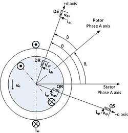
Such complex stator current space vector can be defined in a (d,q) coordinate system with orthogonal components along d (direct) and q (quadrature) axes such that field flux linkage component of current is aligned along the d axis and torque component of current is aligned along the q axis.[21] The induction motor's (d,q) coordinate system can be superimposed to the motor's instantaneous (a,b,c) three-phase sinusoidal system as shown in accompanying image (phases b & c not shown for clarity). Components of the (d,q) system current vector, allow conventional control such as proportional and integral, or PI, control, as with a DC motor.
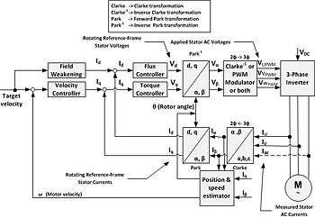
Projections associated with the (d,q) coordinate system typically involve:[19][22][23]
- Forward projection from instantaneous currents to (a,b,c) complex stator current space vector representation of the three-phase sinusoidal system.
- Forward three-to-two phase, (a,b,c)-to-(,) projection using the Clarke transformation. Vector control implementations usually assume ungrounded motor with balanced three-phase currents such that only two motor current phases need to be sensed. Also, backward two-to-three phase, (,)-to-(a,b,c) projection uses space vector PWM modulator or inverse Clarke transformation and one of the other PWM modulators.
- Forward and backward two-to-two phase,(,)-to-(d,q) and (d,q)-to-(,) projections using the Park and inverse Park transformations, respectively.


However, it is not uncommon for sources to use three-to-two, (a,b,c)-to-(d,q) and inverse projections.
While (d,q) coordinate system rotation can arbitrarily be set to any speed, there are three preferred speeds or reference frames:[16]
- Stationary reference frame where (d,q) coordinate system does not rotate;
- Synchronously rotating reference frame where (d,q) coordinate system rotates at synchronous speed;
- Rotor reference frame where (d,q) coordinate system rotates at rotor speed.
Decoupled torque and field currents can thus be derived from raw stator current inputs for control algorithm development.[24]
Whereas magnetic field and torque components in DC motors can be operated relatively simply by separately controlling the respective field and armature currents, economical control of AC motors in variable speed application has required development of microprocessor-based controls[24] with all AC drives now using powerful DSP (digital signal processing) technology.[25]
Inverters can be implemented as either open-loop sensorless or closed-loop FOC, the key limitation of open-loop operation being mimimum speed possible at 100% torque, namely, about 0.8 Hz compared to standstill for closed-loop operation.[9]
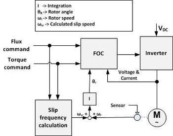
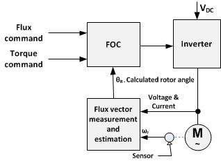
There are two vector control methods, direct or feedback vector control (DFOC) and indirect or feedforward vector control (IFOC), IFOC being more commonly used because in closed-loop mode such drives more easily operate throughout the speed range from zero speed to high-speed field-weakening.[26] In DFOC, flux magnitude and angle feedback signals are directly calculated using so-called voltage or current models. In IFOC, flux space angle feedforward and flux magnitude signals first measure stator currents and rotor speed for then deriving flux space angle proper by summing the rotor angle corresponding to the rotor speed and the calculated reference value of slip angle corresponding to the slip frequency.[27][28]
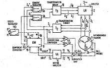
Sensorless control (see Sensorless FOC Block Diagram) of AC drives is attractive for cost and reliability considerations. Sensorless control requires derivation of rotor speed information from measured stator voltage and currents in combination with open-loop estimators or closed-loop observers.[19][20]
Application
1. Stator phase currents are measured, converted to complex space vector in (a,b,c) coordinate system.
2. Current is converted to (, ) coordinate system. Transformed to a coordinate system rotating in rotor reference frame, rotor position being derived by integrating the speed by means of speed measurement sensor.
3. Rotor flux linkage vector is estimated by multiplying the stator current vector with magnetizing inductance Lm and low-pass filtering the result with the rotor no-load time constant Lr/Rr, namely, the rotor inductance to rotor resistance ratio.
4. Current vector is converted to (d,q) coordinate system.
5. d-axis component of the stator current vector is used to control the rotor flux linkage and the imaginary q-axis component is used to control the motor torque. While PI controllers can be used to control these currents, bang-bang type current control provides better dynamic performance.
6. PI controllers provide (d,q) coordinate voltage components. A decoupling term is sometimes added to the controller output to improve control performance to mitigate cross coupling or big and rapid changes in speed, current and flux linkage. PI-controller also sometimes need low-pass filtering at the input or output to prevent the current ripple due to transistor switching from being amplified excessively and destabilizing the control. However, such filtering also limits the dynamic control system performance. High switching frequency (typically more than 10 kHz) is typically required to minimize filtering requirements for high-performance drives such as servo drives.
7. Voltage components are transformed from (d,q) coordinate system to (, ) coordinate system.
8. Voltage components are transformed from (, ) coordinate system to (a,b,c) coordinate system or fed in Pulse Width Modulation (PWM) modulator, or both, for signaling to the power inverter section.
Significant aspects of vector control application:
- Speed or position measurement or some sort of estimation is needed.
- Torque and flux can be changed reasonably fast, in less than 5-10 milliseconds, by changing the references.
- The step response has some overshoot if PI control is used.
- The switching frequency of the transistors is usually constant and set by the modulator.
- The accuracy of the torque depends on the accuracy of the motor parameters used in the control. Thus large errors due to for example rotor temperature changes often are encountered.
- Reasonable processor performance is required; typically the control algorithm has to be calculated at least every millisecond.
Although the vector control algorithm is more complicated than the Direct Torque Control (DTC), the algorithm is not needed to be calculated as frequently as the DTC algorithm. Also the current sensors need not be the best in the market. Thus the cost of the processor and other control hardware is lower making it suitable for applications where the ultimate performance of DTC is not required.
See also
- transform
- Adaptive control
- Control engineering
- Control theory
- Dqo transformation
- Eigenvalues and eigenvectors
- Extended Kalman filter
- Filter (signal processing)
- Frequency response
- Hilbert transform
- Impulse response
- Kalman filter
- Robust control
- Root locus
- Perturbation theory
- Signal-flow graph
- Small signal model
- Sliding mode control
- State observer
- State space representation
- Symmetrical components
- Systems analysis
- Transient response
- Transfer function

References
- ↑ Zambada, Jorge (Nov 8, 2007). "Field-oriented control for motors". MachineDesign.com.
- ↑ Lewin, Chuck (April 10, 2006). "New Developments in Commutation and Motor Control Techniques". DesignNews.com.
- 1 2 568000 DSP Manual (2007). "3-Phase AC Induction Vector Control Drive with Single Shunt Current Sensing" (PDF). Freescale. p. 25, incl. esp. eq. 2–37. Retrieved May 16, 2012.
- ↑ Godbole, Kedar (Sep 23, 2006). "Field oriented control reduces motor size, cost and power consumption in industrial applications". Texas Instruments.
- ↑ Bose, Bimal K. (June 2009). "The Past, Present, and Future of Power Electronics". Industrial Electronics Magazine, IEEE. 3 (2): 11. doi:10.1109/MIE.2009.932709.
- ↑ Murray, Aengus (Sep 27, 2007). "Transforming motion: Field-oriented control of ac motors". EDN. Retrieved 11 May 2012.
- ↑ Yano, Masao; et al. "History of Power Electronics for Motor Drives in Japan" (PDF). p. 6, Fig 13. Retrieved 18 April 2012.
- ↑ Rafiq, Md Abdur (2006). "Fast Speed Response Field-Orientation Control of Induction Motor Drive with Adaptive Neural Integator". Journal of Electrical and Electronics Engineering. University of Istanbul. 6 (2): 229.
- 1 2 3 Drury, Bill (2009). The Control Techniques Drives and Controls Handbook (2nd ed.). Stevenage, Herts, UK: Institution of Engineering and Technology. p. xxx. ISBN 978-1-84919-101-2.
- ↑ Bose, Bimal K. (2006). Power Electronics and Motor Drives : Advances and Trends. Amsterdam: Academic. p. 22. ISBN 978-0-12-088405-6.
- ↑ "The Development of Vector Control Drive".
- ↑ Bose (2006), p. 605
- ↑ Gabriel, R.; Leonhard, W.; Nordby, C.J. (March–April 1980). "Field Oriented Control of Standard AC Motors Using Microprocessors". Trans. on Industry Applications. IA-16 (2): 188. doi:10.1109/tia.1980.4503770.
- ↑ Park, Robert (1929). "Two Reaction Theory of Synchronous Machines". Trans. of the AIEE. 48: 716–730. doi:10.1109/t-aiee.1929.5055275.
- ↑ Heydt,, G. T.; Venkata, S. S.; Balijepalli, N. (Oct 23–24, 2000). "High Impact Papers in Power Engineering, 1900-1999" (PDF). North American Power Symposium (NAPS) 2000: P–1 to P–7. Retrieved May 23, 2012.
- 1 2 Lee, R. J.; Pillay, P.; Harley R. G. (1984). "D,Q Reference Frames for the Simulation of Induction Motors" (PDF). Electric Power Systems Research. EPR. 8: 15–26. doi:10.1016/0378-7796(84)90030-0.
- ↑ Ross, Dave; et al. (2004). "Using the dsPIC30F for Vector Control of an ACIM" (PDF). Microchip. Retrieved May 16, 2012.
- ↑ Popescu, Mircea (2000). Induction Motor Modelling for Vector Control Purposes (PDF). Espoo: Helsinki University of Technology. pp. 13–14. ISBN 951-22-5219-8.
- 1 2 3 4 Holtz, J. (Aug 2002). "Sensorless control of induction motor drives" (PDF). Proceedings of the IEEE. 90 (8): 1359–1394. doi:10.1109/jproc.2002.800726. Retrieved June 3, 2012.
- 1 2 Zambada, Jorge. "The Benefits of FOC Sensorless Motor Control". Appliance Magazine. Retrieved June 3, 2012.
- 1 2 Bose (2006), p. 429
- 1 2 TI (1997). "Field Orientated Control of 3-Phase AC-Motors" (PDF). TI.
- ↑ Didier, Jean-Louis. "Transformation des systèmes triphasés Fortescue, Clarke, Park et Ku". Archived from the original on 7 April 2014. Retrieved June 4, 2012.
- 1 2 Sinha, Naresh Kumar (1986). Microprocessor-based control systems. D. Reidel Publishing. pp. 161 & 175. ISBN 90-277-2287-0.
- ↑ Bose (2006), p. 474
- ↑ Bose (2006), pp. 419, 474
- ↑ Bose (2006), p. 423-425
- ↑ Dong, Gan (Dec 2007). "Sensorless and Efficiency Optimized Induction Machine Control with Associated Converter PWM Modulation Schemes" (PDF). Tennessee Technological University. p. 10. Retrieved May 16, 2012.