Liquid-crystal display
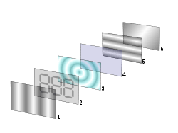
- Polarizing filter film with a vertical axis to polarize light as it enters.
- Glass substrate with ITO electrodes. The shapes of these electrodes will determine the shapes that will appear when the LCD is switched ON. Vertical ridges etched on the surface are
- Twisted nematic liquid crystal.
- Glass substrate with common electrode film (ITO) with horizontal ridges to line up with the horizontal filter.
- Polarizing filter film with a horizontal axis to block/pass light.
- Reflective surface to send light back to viewer. (In a backlit LCD, this layer is replaced with a light source.)
A liquid-crystal display (LCD) is a flat-panel display or other electronic visual display that uses the light-modulating properties of liquid crystals. Liquid crystals do not emit light directly.[1] LCDs are available to display arbitrary images (as in a general-purpose computer display) or fixed images with low information content, which can be displayed or hidden, such as preset words, digits, and 7-segment displays, as in a digital clock. They use the same basic technology, except that arbitrary images are made up of a large number of small pixels, while other displays have larger elements.
LCDs are used in a wide range of applications including computer monitors, televisions, instrument panels, aircraft cockpit displays, and indoor and outdoor signage. Small LCD screens are common in portable consumer devices such as digital cameras, watches, calculators, and mobile telephones, including smartphones. LCD screens are also used on consumer electronics products such as DVD players, video game devices and clocks. LCD screens have replaced heavy, bulky cathode ray tube (CRT) displays in nearly all applications. LCD screens are available in a wider range of screen sizes than CRT and plasma displays, with LCD screens available in sizes ranging from tiny digital watches to huge, big-screen television set.
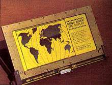
Since LCD screens do not use phosphors, they do not suffer image burn-in when a static image is displayed on a screen for a long time (e.g., the table frame for an aircraft schedule on an indoor sign). LCDs are, however, susceptible to image persistence.[2] The LCD screen is more energy-efficient and can be disposed of more safely than a CRT can. Its low electrical power consumption enables it to be used in battery-powered electronic equipment more efficiently than CRTs can be. It is an electronically modulated optical device made up of any number of segments controlling a layer of liquid crystals and arrayed in front of a light source (backlight) or reflector to produce images in color or monochrome. Liquid crystals were first discovered in 1888.[3] By 2008, annual sales of televisions with LCD screens exceeded sales of CRT units worldwide, and the CRT became obsolete for most purposes.
Overview

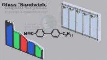
Each pixel of an LCD typically consists of a layer of molecules aligned between two transparent electrodes, and two polarizing filters (parallel and perpendicular), the axes of transmission of which are (in most of the cases) perpendicular to each other. Without the liquid crystal between the polarizing filters, light passing through the first filter would be blocked by the second (crossed) polarizer. Before an electric field is applied, the orientation of the liquid-crystal molecules is determined by the alignment at the surfaces of electrodes. In a twisted nematic (TN) device, the surface alignment directions at the two electrodes are perpendicular to each other, and so the molecules arrange themselves in a helical structure, or twist. This induces the rotation of the polarization of the incident light, and the device appears gray. If the applied voltage is large enough, the liquid crystal molecules in the center of the layer are almost completely untwisted and the polarization of the incident light is not rotated as it passes through the liquid crystal layer. This light will then be mainly polarized perpendicular to the second filter, and thus be blocked and the pixel will appear black. By controlling the voltage applied across the liquid crystal layer in each pixel, light can be allowed to pass through in varying amounts thus constituting different levels of gray.

The optical effect of a TN device in the voltage-on state is far less dependent on variations in the device thickness than that in the voltage-off state. Because of this, TN displays with low information content and no backlighting are usually operated between crossed polarizers such that they appear bright with no voltage (the eye is much more sensitive to variations in the dark state than the bright state). As most of 2010-era LCDs are used in television sets, monitors and smartphones, they have high-resolution matrix arrays of pixels to display arbitrary images using backlighting with a dark background. When no image is displayed, different arrangements are used. For this purpose, TN LCDs are operated between parallel polarizers, whereas IPS LCDs feature crossed polarizers. In many applications IPS LCDs have replaced TN LCDs, in particular in smartphones such as iPhones. Both the liquid crystal material and the alignment layer material contain ionic compounds. If an electric field of one particular polarity is applied for a long period of time, this ionic material is attracted to the surfaces and degrades the device performance. This is avoided either by applying an alternating current or by reversing the polarity of the electric field as the device is addressed (the response of the liquid crystal layer is identical, regardless of the polarity of the applied field).

Displays for a small number of individual digits or fixed symbols (as in digital watches and pocket calculators) can be implemented with independent electrodes for each segment. In contrast, full alphanumeric or variable graphics displays are usually implemented with pixels arranged as a matrix consisting of electrically connected rows on one side of the LC layer and columns on the other side, which makes it possible to address each pixel at the intersections. The general method of matrix addressing consists of sequentially addressing one side of the matrix, for example by selecting the rows one-by-one and applying the picture information on the other side at the columns row-by-row. For details on the various matrix addressing schemes see Passive-matrix and active-matrix addressed LCDs.
History
1880s-1960s
The origins and the complex history of liquid-crystal displays from the perspective of an insider during the early days were described by Joseph A. Castellano in Liquid Gold: The Story of Liquid Crystal Displays and the Creation of an Industry.[4] Another report on the origins and history of LCD from a different perspective until 1991 has been published by Hiroshi Kawamoto, available at the IEEE History Center.[5] A description of Swiss contributions to LCD developments, written by Peter J. Wild, can be looked up as IEEE First-Hand History.[6] In 1888, Friedrich Reinitzer (1858–1927) discovered the liquid crystalline nature of cholesterol extracted from carrots (that is, two melting points and generation of colors) and published his findings at a meeting of the Vienna Chemical Society on May 3, 1888 (F. Reinitzer: Beiträge zur Kenntniss des Cholesterins, Monatshefte für Chemie (Wien) 9, 421–441 (1888)).[7] In 1904, Otto Lehmann published his work "Flüssige Kristalle" (Liquid Crystals). In 1911, Charles Mauguin first experimented with liquid crystals confined between plates in thin layers.
In 1922, Georges Friedel described the structure and properties of liquid crystals and classified them in 3 types (nematics, smectics and cholesterics). In 1927, Vsevolod Frederiks devised the electrically switched light valve, called the Fréedericksz transition, the essential effect of all LCD technology. In 1936, the Marconi Wireless Telegraph company patented the first practical application of the technology, "The Liquid Crystal Light Valve". In 1962, the first major English language publication on the subject "Molecular Structure and Properties of Liquid Crystals", by Dr. George W. Gray.[8] In 1962, Richard Williams of RCA found that liquid crystals had some interesting electro-optic characteristics and he realized an electro-optical effect by generating stripe-patterns in a thin layer of liquid crystal material by the application of a voltage. This effect is based on an electro-hydrodynamic instability forming what are now called "Williams domains" inside the liquid crystal.[9]
In 1964, George H. Heilmeier, then working at the RCA laboratories on the effect discovered by Williams achieved the switching of colors by field-induced realignment of dichroic dyes in a homeotropically oriented liquid crystal. Practical problems with this new electro-optical effect made Heilmeier continue to work on scattering effects in liquid crystals and finally the achievement of the first operational liquid-crystal display based on what he called the dynamic scattering mode (DSM). Application of a voltage to a DSM display switches the initially clear transparent liquid crystal layer into a milky turbid state. DSM displays could be operated in transmissive and in reflective mode but they required a considerable current to flow for their operation.[10][11][12][13] George H. Heilmeier was inducted in the National Inventors Hall of Fame[14] and credited with the invention of LCDs. Heilmeier's work is an IEEE Milestone.[15] In the late 1960s, pioneering work on liquid crystals was undertaken by the UK's Royal Radar Establishment at Malvern, England. The team at RRE supported ongoing work by George William Gray and his team at the University of Hull who ultimately discovered the cyanobiphenyl liquid crystals, which had correct stability and temperature properties for application in LCDs.
1970s-1980s
On December 4, 1970, the twisted nematic field effect in liquid crystals was filed for patent by Hoffmann-LaRoche in Switzerland, (Swiss patent No. 532 261) with Wolfgang Helfrich and Martin Schadt (then working for the Central Research Laboratories) listed as inventors.[10] Hoffmann-La Roche then licensed the invention to the Swiss manufacturer Brown, Boveri & Cie who produced displays for wristwatches during the 1970s and also to Japanese electronics industry, which soon produced the first digital quartz wrist watches with TN-LCDs and numerous other products. James Fergason, while working with Sardari Arora and Alfred Saupe at Kent State University Liquid Crystal Institute, filed an identical patent in the United States on April 22, 1971.[16] In 1971 the company of Fergason ILIXCO (now LXD Incorporated) produced the first LCDs based on the TN-effect, which soon superseded the poor-quality DSM types due to improvements of lower operating voltages and lower power consumption. In 1972, the first active-matrix liquid-crystal display panel was produced in the United States by T Peter Brody's team at Westinghouse, in Pittsburgh, Pennsylvania.[17] In 1983, researchers at Brown, Boveri & Cie (BBC), Switzerland, invented the super-twisted nematic (STN) structure for passive matrix addressed LCDs. H. Amstutz et al. were listed as inventors in the corresponding patent applications filed in Switzerland on July 7, 1983, and October 28, 1983. Patents were granted in Switzerland CH 665491, Europe EP 0131216,[18] U.S. Patent 4,634,229 and many more countries.
1990s-2010s
In 1990, under different titles, inventors conceived electro optical effects as alternatives to twisted nematic field effect LCDs (TN- and STN- LCDs). One approach was to use interdigital electrodes on one glass substrate only to produce an electric field essentially parallel to the glass substrates.[19][20] To take full advantage of the properties of this In Plane Switching (IPS) technology further work was needed. After thorough analysis, details of advantageous embodiments are filed in Germany by Guenter Baur et al. and patented in various countries.[21][22] The Fraunhofer Institute in Freiburg, where the inventors worked, assigns these patents to Merck KGaA, Darmstadt, a supplier of LC substances. In 1992, shortly thereafter, engineers at Hitachi work out various practical details of the IPS technology to interconnect the thin-film transistor array as a matrix and to avoid undesirable stray fields in between pixels.[23][24] Hitachi also improves the viewing angle dependence further by optimizing the shape of the electrodes (Super IPS). NEC and Hitachi become early manufacturers of active-matrix addressed LCDs based on the IPS technology. This is a milestone for implementing large-screen LCDs having acceptable visual performance for flat-panel computer monitors and television screens. In 1996, Samsung developed the optical patterning technique that enables multi-domain LCD. Multi-domain and In Plane Switching subsequently remain the dominant LCD designs through 2006.[25] In the fourth quarter of 2006, LCD televisions surpassed CRTs in worldwide sales for the first time.[26] LCD TVs were projected to account 50% of the 200 million TVs to be shipped globally in 2006, according to Display Bank.[27] In October 2011, Toshiba announced 2560 × 1600 pixels on a 6.1-inch (155 mm) LCD panel, suitable for use in a tablet computer,[28] especially for Chinese character display.
Illumination
Since LCD panels produce no light of their own, they require external light to produce a visible image. In a "transmissive" type of LCD, this light is provided at the back of the glass "stack" and is called the backlight. While passive-matrix displays are usually not backlit (e.g. calculators, wristwatches), active-matrix displays almost always are.[29][30]
The common implementations of LCD backlight technology are:

- CCFL: The LCD panel is lit either by two cold cathode fluorescent lamps placed at opposite edges of the display or an array of parallel CCFLs behind larger displays. A diffuser then spreads the light out evenly across the whole display. For many years, this technology had been used almost exclusively. Unlike white LEDs, most CCFLs have an even-white spectral output resulting in better color gamut for the display. However, CCFLs are less energy efficient than LEDs and require a somewhat costly inverter to convert whatever DC voltage the device uses (usually 5 or 12 V) to ~1000 V needed to light a CCFL.[31] The thickness of the inverter transformers also limit how thin the display can be made.
- EL-WLED: The LCD panel is lit by a row of white LEDs placed at one or more edges of the screen. A light diffuser is then used to spread the light evenly across the whole display. As of 2012, this design is the most popular one in desktop computer monitors. It allows for the thinnest displays. Some LCD monitors using this technology have a feature called "Dynamic Contrast" where the backlight is dimmed to the brightest color that appears on the screen, allowing the 1000:1 contrast ratio of the LCD panel to be scaled to different light intensities, resulting in the "30000:1" contrast ratios seen in the advertising on some of these monitors. Since computer screen images usually have full white somewhere in the image, the backlight will usually be at full intensity, making this "feature" mostly a marketing gimmick.
- WLED array: The LCD panel is lit by a full array of white LEDs placed behind a diffuser behind the panel. LCDs that use this implementation will usually have the ability to dim the LEDs in the dark areas of the image being displayed, effectively increasing the contrast ratio of the display. As of 2012, this design gets most of its use from upscale, larger-screen LCD televisions.
- RGB-LED: Similar to the WLED array, except the panel is lit by a full array of RGB LEDs. While displays lit with white LEDs usually have a poorer color gamut than CCFL lit displays, panels lit with RGB LEDs have very wide color gamuts. This implementation is most popular on professional graphics editing LCDs. As of 2012, LCDs in this category usually cost more than $1000.
Today, most LCD screens are being designed with an LED backlight instead of the traditional CCFL backlight.
Connection to other circuits
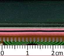
LCD panels typically use thinly-coated metallic conductive pathways on a glass substrate to form the cell circuitry to operate the panel. It is usually not possible to use soldering techniques to directly connect the panel to a separate copper-etched circuit board. Instead, interfacing is accomplished using either adhesive plastic ribbon with conductive traces glued to the edges of the LCD panel, or with an elastomeric connector, which is a strip of rubber or silicone with alternating layers of conductive and insulating pathways, pressed between contact pads on the LCD and mating contact pads on a circuit board.
Passive and active-matrix
Monochrome and later color passive-matrix LCDs were standard in most early laptops (although a few used plasma displays[32][33]) and the original Nintendo Game Boy[34] until the mid-1990s, when color active-matrix became standard on all laptops. The commercially unsuccessful Macintosh Portable (released in 1989) was one of the first to use an active-matrix display (though still monochrome). Passive-matrix LCDs are still used in the 2010s for applications less demanding than laptops and TVs, such as inexpensive calculators. In particular, these are used on portable devices where less information content needs to be displayed, lowest power consumption (no backlight) and low cost are desired or readability in direct sunlight is needed.
Displays having a passive-matrix structure are employing super-twisted nematic STN (invented by Brown Boveri Research Center, Baden, Switzerland, in 1983; scientific details were published[35]) or double-layer STN (DSTN) technology (the latter of which addresses a color-shifting problem with the former), and color-STN (CSTN) in which color is added by using an internal filter. STN LCDs have been optimized for passive-matrix addressing. They exhibit a sharper threshold of the contrast-vs-voltage characteristic than the original TN LCDs. This is important, because pixels are subjected to partial voltages even while not selected. Crosstalk between activated and non-activated pixels has to be handled properly by keeping the RMS voltage of non-activated pixels below the threshold voltage,[36] while activated pixels are subjected to voltages above threshold.[37] STN LCDs have to be continuously refreshed by alternating pulsed voltages of one polarity during one frame and pulses of opposite polarity during the next frame. Individual pixels are addressed by the corresponding row and column circuits. This type of display is called passive-matrix addressed, because the pixel must retain its state between refreshes without the benefit of a steady electrical charge. As the number of pixels (and, correspondingly, columns and rows) increases, this type of display becomes less feasible. Slow response times and poor contrast are typical of passive-matrix addressed LCDs with too many pixels.
In the 2010s, zero-power (bistable) LCDs do not require continuous refreshing. Rewriting is only required for picture information changes. Potentially, passive-matrix addressing can be used with these new devices, if their write/erase characteristics are suitable. High-resolution color displays, such as modern LCD computer monitors and televisions, use an active-matrix structure. A matrix of thin-film transistors (TFTs) is added to the electrodes in contact with the LC layer. Each pixel has its own dedicated transistor, allowing each column line to access one pixel. When a row line is selected, all of the column lines are connected to a row of pixels and voltages corresponding to the picture information are driven onto all of the column lines. The row line is then deactivated and the next row line is selected. All of the row lines are selected in sequence during a refresh operation. Active-matrix addressed displays look brighter and sharper than passive-matrix addressed displays of the same size, and generally have quicker response times, producing much better images.
Active-matrix technologies

Twisted nematic (TN)
Twisted nematic displays contain liquid crystals that twist and untwist at varying degrees to allow light to pass through. When no voltage is applied to a TN liquid crystal cell, polarized light passes through the 90-degrees twisted LC layer. In proportion to the voltage applied, the liquid crystals untwist changing the polarization and blocking the light's path. By properly adjusting the level of the voltage almost any gray level or transmission can be achieved.
In-plane switching (IPS)
In-plane switching is an LCD technology that aligns the liquid crystals in a plane parallel to the glass substrates. In this method, the electrical field is applied through opposite electrodes on the same glass substrate, so that the liquid crystals can be reoriented (switched) essentially in the same plane, although fringe fields inhibit a homogeneous reorientation. This requires two transistors for each pixel instead of the single transistor needed for a standard thin-film transistor (TFT) display. Before LG Enhanced IPS was introduced in 2009, the additional transistors resulted in blocking more transmission area, thus requiring a brighter backlight and consuming more power, making this type of display less desirable for notebook computers. Currently Panasonic is using an enhanced version eIPS for their large size LCD-TV products as well as Hewlett-Packard in its WebOS based TouchPad tablet and their Chromebook 11.
IPS LCD vs AMOLED
LG claimed the smartphone LG Optimus Black (IPS LCD (LCD NOVA)) has the brightness up to 700 nits, while the competitor has only IPS LCD with 518 nits and double an active-matrix OLED (AMOLED) display with 305 nits. LG also claimed the NOVA display to be 50 percent more efficient than regular LCDs and to consume only 50 percent of the power of AMOLED displays when producing white on screen.[38] When it comes to contrast ratio, AMOLED display still performs best due to its underlying technology, where the black levels are displayed as pitch black and not as dark gray. On August 24, 2011, Nokia announced the Nokia 701 and also made the claim of the world's brightest display at 1000 nits. The screen also had Nokia's Clearblack layer, improving the contrast ratio and bringing it closer to that of the AMOLED screens.
Super In-plane switching (S-IPS)
Super-IPS was later introduced after in-plane switching with even better response times and color reproduction.[39]
Advanced fringe field switching (AFFS)
Known as fringe field switching (FFS) until 2003,[40] advanced fringe field switching is similar to IPS or S-IPS offering superior performance and color gamut with high luminosity. AFFS was developed by Hydis Technologies Co., Ltd, Korea (formally Hyundai Electronics, LCD Task Force).[41] AFFS-applied notebook applications minimize color distortion while maintaining a wider viewing angle for a professional display. Color shift and deviation caused by light leakage is corrected by optimizing the white gamut which also enhances white/gray reproduction. In 2004, Hydis Technologies Co., Ltd licensed AFFS to Japan's Hitachi Displays. Hitachi is using AFFS to manufacture high-end panels. In 2006, HYDIS licensed AFFS to Sanyo Epson Imaging Devices Corporation. Shortly thereafter, Hydis introduced a high-transmittance evolution of the AFFS display, called HFFS (FFS+). Hydis introduced AFFS+ with improved outdoor readability in 2007. AFFS panels are mostly utilized in the cockpits of latest commercial aircraft displays. But is no longer produced as of February 2015.[42][43][44]
Vertical alignment (VA)
Vertical-alignment displays are a form of LCDs in which the liquid crystals naturally align vertically to the glass substrates. When no voltage is applied, the liquid crystals remain perpendicular to the substrate, creating a black display between crossed polarizers. When voltage is applied, the liquid crystals shift to a tilted position, allowing light to pass through and create a gray-scale display depending on the amount of tilt generated by the electric field. It has a deeper-black background, a higher contrast ratio, a wider viewing angle, and better image quality at extreme temperatures than traditional twisted-nematic displays.[45]
Blue phase mode
Blue phase mode LCDs have been shown as engineering samples early in 2008, but they are not in mass-production. The physics of blue phase mode LCDs suggest that very short switching times (~1 ms) can be achieved, so time sequential color control can possibly be realized and expensive color filters would be obsolete.
Quality control
Some LCD panels have defective transistors, causing permanently lit or unlit pixels which are commonly referred to as stuck pixels or dead pixels respectively. Unlike integrated circuits (ICs), LCD panels with a few defective transistors are usually still usable. Manufacturers' policies for the acceptable number of defective pixels vary greatly. At one point, Samsung held a zero-tolerance policy for LCD monitors sold in Korea.[46] As of 2005, though, Samsung adheres to the less restrictive ISO 13406-2 standard.[47] Other companies have been known to tolerate as many as 11 dead pixels in their policies.[48]
Dead pixel policies are often hotly debated between manufacturers and customers. To regulate the acceptability of defects and to protect the end user, ISO released the ISO 13406-2 standard.[49] However, not every LCD manufacturer conforms to the ISO standard and the ISO standard is quite often interpreted in different ways. LCD panels are more likely to have defects than most ICs due to their larger size. For example, a 300 mm SVGA LCD has 8 defects and a 150 mm wafer has only 3 defects. However, 134 of the 137 dies on the wafer will be acceptable, whereas rejection of the whole LCD panel would be a 0% yield. In recent years, quality control has been improved. An SVGA LCD panel with 4 defective pixels is usually considered defective and customers can request an exchange for a new one. Some manufacturers, notably in South Korea where some of the largest LCD panel manufacturers, such as LG, are located, now have "zero defective pixel guarantee", which is an extra screening process which can then determine "A" and "B" grade panels. Many manufacturers would replace a product even with one defective pixel. Even where such guarantees do not exist, the location of defective pixels is important. A display with only a few defective pixels may be unacceptable if the defective pixels are near each other. LCD panels also have defects known as clouding (or less commonly mura), which describes the uneven patches of changes in luminance. It is most visible in dark or black areas of displayed scenes.[50]
Zero-power (bistable) displays
The zenithal bistable device (ZBD), developed by QinetiQ (formerly DERA), can retain an image without power. The crystals may exist in one of two stable orientations ("Black" and "White") and power is only required to change the image. ZBD Displays is a spin-off company from QinetiQ who manufactured both grayscale and color ZBD devices. Kent Displays has also developed a "no power" display that uses polymer stabilized cholesteric liquid crystal (ChLCD). In 2009 Kent demonstrated the use of a ChLCD to cover the entire surface of a mobile phone, allowing it to change colors, and keep that color even when power is cut off.[51] In 2004 researchers at the University of Oxford demonstrated two new types of zero-power bistable LCDs based on Zenithal bistable techniques.[52] Several bistable technologies, like the 360° BTN and the bistable cholesteric, depend mainly on the bulk properties of the liquid crystal (LC) and use standard strong anchoring, with alignment films and LC mixtures similar to the traditional monostable materials. Other bistable technologies, e.g. BiNem technology, are based mainly on the surface properties and need specific weak anchoring materials.
Specifications
Important factors to consider when evaluating an LCD display:
- Resolution versus range: Fundamentally resolution is the "granularity" (or number of levels) with which a performance feature of the display is divided. Resolution is often confused with range or the total end-to-end output of the display. Each of the major features of a display has both a resolution and a range that are tied to each other but very different. Frequently the range is an inherent limitation of the display while the resolution is a function of the electronics that make the display work.
- Spatial performance: LCDs come in only one size for a variety of applications and a variety of resolutions within each of those applications. LCD spatial performance is also sometimes described in terms of a "dot pitch". The size (or spatial range) of an LCD is always described in terms of the diagonal distance from one corner to its opposite. This is an historical remnant from the early days of CRT television when CRT screens were manufactured on the bottoms of glass bottles, a direct extension of cathode ray tubes used in oscilloscopes. The diameter of the bottle determined the size of the screen. Later, when television screens became a somewhat rectangular shape, they started to be measured diagonally to compare with the older, round, screens.[53]
The spatial resolution of an LCD is expressed by the number of columns and rows of pixels (e.g., 1024×768). Each pixel is usually composed 3 sub-pixels, a red, a green, and a blue one. This had been one of the few features of LCD performance that was easily understood and not subject to interpretation. However, there are newer schemes that share sub-pixels among pixels and to add additional colors of sub-pixels. So going forward, spatial resolution may now be more subject to interpretation.
One external factor to consider in evaluating display resolution is the resolution of the viewer's eyes. Assuming 20/20 vision, the resolution of the eyes is about one minute of arc. In practical terms that means for an older standard definition TV set the ideal viewing distance was about eight times the height (not diagonal) of the screen away. At that distance the individual rows of pixels merge into a solid. If the viewer were closer to the screen than that, they would be able to see the individual rows of pixels. When observed from farther away, the image of the rows of pixels still merge, but the total image becomes smaller as the distance increases. For an HDTV set with slightly more than twice the number of rows of pixels, the ideal viewing distance is about half what it is for a standard definition set. The higher the resolution, the closer the viewer can sit or the larger the set can usefully be sitting at the same distance as an older standard definition display.
For a computer monitor or some other LCD that is being viewed from a very close distance, resolution is often expressed in terms of dot pitch or pixels per inch (or pixels per cm). This is consistent with the printing industry (another form of a display). Magazines, and other premium printed media are often at 300 dots per inch (118 dpcm). As with the distance discussion above, this provides a very solid looking and detailed image. LCDs, particularly on mobile devices, are frequently much less than this as the higher the dot pitch, the more optically inefficient the display and the more power it burns. Running the LCD is frequently half, or more, of the power consumed by a mobile device. An additional consideration in spatial performance are viewing cone and aspect ratio. The Aspect ratio is the ratio of the width to the height (for example, 4:3, 5:4, 16:9 or 16:10). Older, standard definition TVs were 4:3. Newer High Definition televisions (HDTV) are 16:9, as are most new notebook computers. Movies are often filmed in much different (wider) aspect ratios, which is why there will frequently still be black bars at the top and bottom of an HDTV screen.
The Viewing Angle of an LCD may be important depending on its use or location. The viewing angle is usually measured as the angle where the contrast of the LCD falls below 10:1. At this point, the colors usually start to change and can even invert, red becoming green and so forth. Viewing angles for LCDs used to be very restrictive however, improved optical films have been developed that give almost 180 degree viewing angles from left to right. Top to bottom viewing angles may still be restrictive, by design, as looking at an LCD from an extreme up or down angle is not a common usage model and these photons are wasted. Manufacturers commonly focus the light in a left to right plane to obtain a brighter image here.
- Temporal/timing performance: Contrary to spatial performance, temporal performance is a feature where smaller is better. Specifically, the range is the pixel response time of an LCD, or how quickly a sub-pixel's brightness changes from one level to another. For LCD monitors, this is measured in btb (black to black) or gtg (gray to gray). These different types of measurements make comparison difficult.[54] Further, this number is almost never published in sales advertising.
Refresh rate or the temporal resolution of an LCD is the number of times per second in which the display draws the data it is being given. Since activated LCD pixels do not flash on/off between frames, LCD monitors exhibit no refresh-induced flicker, no matter how low the refresh rate.[55] High-end LCD televisions now feature up to 240 Hz refresh rate, which requires advanced digital processing to insert additional interpolated frames between the real images to smooth the image motion. However, such high refresh rates may not be actually supported by pixel response times and the result can be visual artifacts that distort the image in unpleasant ways.
Temporal performance can be further taxed if it is a 3D display. 3D displays work by showing a different series of images to each eye, alternating from eye to eye. Thus a 3D display must display twice as many images in the same period of time as a conventional display, and consequently the response time of the LCD is more important. 3D LCDs with marginal response times will be perceived as causing "image smearing". These artifacts are most noticeable in a person's black and white vision (rod cells) than in color vision (cone cells). Thus they will be more likely to see flicker or any sort of temporal distortion in a display image by not looking directly at the display, because their eyes' rod cells are mostly grouped at the periphery of their vision.
- Color performance: There are many terms to describe color performance of an LCD. They include color gamut which is the range of colors that can be displayed and color depth which is the color resolution or the resolution or fineness with which the color range is divided. Although color gamut can be expressed as three pairs of numbers, the XY coordinates within color space of the reddest red, greenest green, and bluest blue, it is usually expressed as a ratio of the total area within color space that a display can show relative to some standard such as saying that a display was "120% of NTSC". NTSC is the National Television Standards Committee, the old standard definition TV specification. Color gamut is a relatively straight forward feature. However, with clever optical techniques that are based on the way humans see color, termed color stretch,[56] colors can be shown that are outside of the nominal range of the display. In any case, color range is rarely discussed as a feature of the display as LCDs are designed to match the color ranges of the content that they are intended to show. Having a color range that exceeds the content is a useless feature.[57]
- Color depth or color support is sometimes expressed in bits, either as the number of bits per sub-pixel or the number of bits per pixel. This can be ambiguous as an 8-bit color LCD can be 8 total bits spread between red, green, and blue or 8 bits each for each color in a different display. Further, LCDs sometimes use a technique called dithering which is time averaging colors to get intermediate colors, such as alternating between two different colors to get a color in between. This doubles the number of colors that can be displayed; however this is done at the expense of the temporal performance of the display. Dithering is commonly used on computer displays where the images are mostly static and the temporal performance is unimportant. When color depth is reported as color support, it is usually stated in terms of number of colors the LCD can show. The number of colors is the translation from the base 2-bit numbers into common base-10. For example, 8-bit color is 2 to the 8th power, which is 256 colors. 24-bit color is 2 to the 24th power, or 256 x 256 x 256, a total of 16,777,216 colors. The color resolution of the human eye depends on both the range of colors being sliced and the number of slices; but for most common displays the limit is about 28-bit color. LCD TVs commonly display more than that as the digital processing can introduce color distortions and the additional levels of color are needed to ensure true colors.
There are additional aspects to LCD color and color management, such as white point and gamma correction, which describe what color white is and how the other colors are displayed relative to white. LCD televisions also frequently have facial recognition software, which recognizes that an image on the screen is a face and both adjust the color and the focus differently from the rest of the image. These adjustments can have important effects on the consumer, but are not easily quantifiable; people like what they like and everyone does not like the same thing. There is no substitute for looking at the LCD one is going to buy before buying it. Portrait film, another form of display, has similar adjustments built into it. Many years ago, Kodak had to overcome initial rejection of its portrait film in Japan because of these adjustments. In the U.S., people generally prefer a more colorful facial image than in reality (higher color saturation). In Japan, consumers generally prefer a less saturated image. The film that Kodak initially sent to Japan was biased in the wrong direction for Japanese consumers. Television monitors have their built-in biases as well.
- Brightness and contrast ratio: Contrast ratio is the ratio of the brightness of a full-on pixel to a full-off pixel and, as such, would be directly tied to brightness if not for the invention of the blinking backlight (or burst dimming). The LCD itself is only a light valve and does not generate light; the light comes from a backlight that is either a fluorescent tube or a set of LEDs. The blinking backlight was developed to improve the motion performance of LCDs by turning the backlight off while the liquid crystals were in transition from one image to another. However, a side benefit of the blinking backlight was infinite contrast. The contrast reported on most LCDs is what the LCD is qualified at, not its actual performance. In any case, there are two large caveats to contrast ratio as a measure of LCD performance.
The first caveat is that contrast ratios are measured in a completely dark room. In actual use, the room is never completely dark, as one will always have the light from the LCD itself. Beyond that, there may be sunlight coming in through a window or other room lights that reflect off of the surface of the LCD and degrades the contrast. As a practical matter, the contrast of an LCD, or any display, is governed by the amount of surface reflections, not by the performance of the display. The second caveat is that the human eye can only image a contrast ratio of a maximum of about 200:1. Black print on a white paper is about 15–20:1. That is why viewing angles are specified to the point where they fall below 10:1. A 10:1 image is not great, but is discernible.
Brightness is usually stated as the maximum output of the LCD. In the CRT era, Trinitron CRTs had a brightness advantage over the competition, so brightness was commonly discussed in TV advertising. With current LCD technology, brightness, though important, is usually similar from maker to maker and consequently is not discussed much, except for laptop LCDs and other displays that will be viewed in bright sunlight. In general, brighter is better, but there is always a trade-off between brightness and battery life in a mobile device.
Advantages and disadvantages
Advantages
- Very compact, thin and light, especially in comparison with bulky, heavy CRT displays. This makes LCD-enabled portable devices to be lighter and easy to carry. It also means that purchasers of large screen LCD televisions can move their TVs into their home with just two family members; in contrast, moving a 38" CRT TV (the largest screen size available for home use) would require hiring two movers.
- Low power consumption. Depending on the set display brightness and content being displayed, the older CCFT backlit models typically use 30–50% of the power a CRT monitor of the same size viewing area would use, and the modern LED backlit models typically use 10–25% of the power a CRT monitor would use.[58]
- Very little heat emitted during operation, due to low power consumption.
- No geometric distortion.
- The possible ability to have little or no "flicker" depending on backlight technology.
- Usually no refresh-rate flicker, because the LCD pixels hold their state between refreshes (which are usually done at 200 Hz or faster, regardless of the input refresh rate).
- Is very thin compared to a CRT monitor, which allows the monitor to be placed farther back from the user, reducing close-focusing related eye-strain.
- Razor sharp image with no bleeding/smearing when operated at native resolution.
- Emits much less undesirable electromagnetic radiation than a CRT monitor (in the extremely low frequency range).[59][60]
- Can be made in almost any size or shape.
- No theoretical resolution limit. When multiple LCD panels are used together to create a single canvas, each additional panel increases the total resolution of the display, which is commonly called “stacked” resolution.[61]
- Can be made to large sizes (more than 60 inches (150 cm)) lightly and relatively inexpensively due to established mass production.
- Masking effect: the LCD grid can mask the effects of spatial and grayscale quantization, creating the illusion of higher image quality.[62]
- Unconstrained by geographical (hemispheric) location of device with respect to Earth's magnetic field.
- As an inherently digital device, the LCD can natively display digital data from a DVI or HDMI connection without requiring conversion to analog. Some LCD panels have native fiber optic inputs in addition to DVI and HDMI.[63]
- Many LCD monitors are powered by an external 12 V power supply, which means that (with a proper cable) they can also be run directly on one of the computer's 12 V power supply outputs, removing the overhead and quiescent power consumption of the monitor's own power supply. This can increase the power efficiency, especially if the computer has a high-efficiency PFC power supply. This is also convenient because the monitor will power on when the computer is turned on, and will power off when the computer sleeps or is shutdown.
- Can be made with small frame borders. This enables users to put together multiple LCD screens and use the entire area as "one screen".
Disadvantages
- Limited viewing angle in some (mostly older or cheap) monitors, causing color, saturation, contrast and brightness to vary, even within the intended viewing angle, by variations in posture or viewer positioning.
- Uneven backlighting in some (mostly older) monitors, causing brightness distortion, especially toward the edges.
- Black levels may appear unacceptably bright because individual liquid crystals cannot completely block all of the backlight from passing through.
- Display motion blur on moving objects caused by slow response times (>8 ms) and eye-tracking on a sample-and-hold display, unless a strobing backlight is used. However, this strobing can cause eye-strain, as is noted next:
- As of 2012, most implementations of LCD backlighting use pulse-width modulation (PWM) to dim the display,[64] which makes the screen flicker more acutely (this does not mean visibly) than a CRT monitor at 85 Hz refresh rate would (this is because the entire screen is strobing on and off rather than a CRT's phosphor sustained dot which continually scans across the display, leaving some part of the display always lit), causing severe eye-strain for some people.[65][66] Unfortunately, many of these people don't know that their eye-strain is being caused by the invisible strobe effect of PWM.[67] This problem is worse on many of the new LED backlit monitors, because the LEDs have a faster turn-on/turn-off time than a CCFL lamp.
- Only one native resolution. Displaying any other resolution either requires a video scaler, causing blurriness and jagged edges; or running the display at native resolution using 1:1 pixel mapping, causing the image either not to fill the screen (letterboxed display), or to run off the lower or right edges of the screen.
- Fixed bit depth (also called "color depth"). Many cheaper LCDs are only able to display 262,000 colors. 8-bit S-IPS panels can display 16 million colors and have significantly better black level, but are expensive and have slower response time.
- Low refresh rate. All but a few high-end monitors support no higher than 60 or 75 Hz; while this does not cause visible flicker due to the LCD panel's high internal refresh rate, the low input refresh rate still limits the maximum frame-rate that can be displayed, negatively impacting gaming and 3D graphics.
- Input lag, because the LCD's A/D converter waits for each frame to be completely outputted before "drawing" it to the LCD panel. Many LCD monitors do post-processing before displaying the image in an attempt to compensate for poor color fidelity, which adds an additional lag. Further, a video scaler must be used when displaying non-native resolutions, which adds yet more time lag. Scaling and post processing are usually done in a single chip on modern monitors, but each function that chip performs adds some delay. Some displays have a video gaming mode which disables all or most processing to reduce perceivable input lag.[68]
- Dead or stuck pixels may occur during manufacturing or while a consumer owns a screen. A dead pixel will glow with color even on an all-black screen. Although this may be acceptable for LCD screens in some uses (e.g., surfing the Internet or doing homework on a computer), a dead pixel on a movie or digital photo image may be problematic for viewers.
- Subject to burn-in effect, although the cause differs from CRT and the effect may not be permanent, a static image can cause burn-in in a matter of hours in badly designed displays.
- In a constant-on situation, thermalization may occur in case of bad thermal management, in which part of the screen has overheated and looks discolored compared to the rest of the screen.
- Loss of brightness and much slower response times in low temperature environments. In sub-zero environments, LCD screens may cease to function without the use of supplemental heating. This can make it hard to use LCD screens in Arctic or northern areas.
- Loss of contrast in high temperature environments.
- Not usually designed to allow easy replacement of the backlight.
- Poor display in direct sunlight (unless matte-based instead of glossy-based), often completely unviewable. Transflective LCDs provide a large improvement by reflecting natural light, but are dimmer when relying on the backlight and so they have only been adopted for specific uses such as outdoor vending machines, gasoline pumps, car dashboards and alarm clocks.
- Cannot be used with light guns/pens.
- Hard to read when wearing polarized sunglasses.
Chemicals used
Several different families of liquid crystals are used in liquid crystals. The molecules used have to be anisotropic, and to exhibit mutual attraction. Polarizable rod-shaped molecules (biphenyls, terphenyls, etc.) are common. A common form is a pair of aromatic benzene rings, with a nonpolar moiety (pentyl, heptyl, octyl, or alkyl oxy group) on one end and polar (nitrile, halogen) on the other. Sometimes the benzene rings are separated with an acetylene group, ethylene, CH=N, CH=NO, N=N, N=NO, or ester group. In practice, eutectic mixtures of several chemicals are used, to achieve wider temperature operating range (-10..+60 °C for low-end and -20..+100 °C for high-performance displays). For example, the E7 mixture is composed of three biphenyls and one terphenyl: 39 wt.% of 4'-pentyl[1,1'-biphenyl]-4-carbonitrile (nematic range 24..35 °C), 36 wt.% of 4'-heptyl[1,1'-biphenyl]-4-carbonitrile (nematic range 30..43 °C), 16 wt.% of 4'-octoxy[1,1'-biphenyl]-4-carbonitrile (nematic range 54..80 °C), and 9 wt.% of 4-pentyl[1,1':4',1-terphenyl]-4-carbonitrile (nematic range 131..240 °C).[69]
See also
References
- ↑ http://www.merriam-webster.com/dictionary/lcd
- ↑ "LCD Image Persistence". Fujitsu technical support. Fujitsu. Retrieved December 11, 2011.
- ↑ Jonathan W. Steed & Jerry L. Atwood (2009). Supramolecular Chemistry (2nd ed.). John Wiley and Sons. p. 844. ISBN 978-0-470-51234-0.
- ↑ Liquid Gold: The Story of Liquid Crystal Displays and the Creation of an Industry, Joseph A. Castellano, 2005 World Scientific Publishing Co. Pte. Ltd., ISBN 981-238-956-3.
- ↑ Kawamoto, Hiroshi (2002). "The History of Liquid-Crystal Displays" (PDF). Proceedings of the IEEE. 90 (4): 460–500. doi:10.1109/JPROC.2002.1002521.
- ↑ "First-Hand Histories: Liquid Crystal Display Evolution - Swiss Contributions". IEEE Global History Network. IEEE. Retrieved July 31, 2012.
- ↑ Tim Sluckin: Ueber die Natur der kristallinischen Flüssigkeiten und flüssigen Kristalle (About the Nature of Crystallised Liquids and Liquid Crystals), Bunsen-Magazin, 7.Jahrgang, 5/2005
- ↑ Gray, George W.; Kelly, Stephen M. (1999). "Liquid crystals for twisted nematic display devices". Journal of Materials Chemistry. 9 (9): 2037–2050. doi:10.1039/a902682g.
- ↑ Williams, R. (1963). "Domains in liquid crystals". J. Phys. Chem. 39: 382–388. doi:10.1063/1.1734257.
- 1 2 Castellano, Joseph A. (2006). "Modifying Light". American Scientist. 94 (5): 438–445. doi:10.1511/2006.61.438.
- ↑ Heilmeier, George; Castellano, Joseph; Zanoni, Louis (1969). "Guest-Host Interactions in Nematic Liquid Crystals". Molecular Crystals and Liquid Crystals. 8: 293–304. doi:10.1080/15421406908084910.
- ↑ Heilmeier, G. H.; Zanoni, L. A.; Barton, L. A. (1968). "Dynamic scattering: A new electrooptic effect in certain classes of nematic liquid crystals". Proc. IEEE. 56: 1162–1171. doi:10.1109/proc.1968.6513.
- ↑ Gross, Benjamin (November 2012). "How RCA lost the LCD". IEEE Spectrum. 49 (11): 38–44. doi:10.1109/mspec.2012.6341205.
- ↑ National Inventors Hall of Fame (Retrieved 2014-04-25)
- ↑ "Milestones: Liquid Crystal Display, 1968". IEEE Global History Network. IEEE. Retrieved August 4, 2011.
- ↑ "Modifying Light". American Scientist Online.
- ↑ Brody, T.P., "Birth of the Active Matrix", Information Display, Vol. 13, No. 10, 1997, pp. 28–32.
- ↑ European Patent No. EP 0131216: Amstutz H., Heimgartner D., Kaufmann M., Scheffer T.J., "Flüssigkristallanzeige," Oct. 28, 1987.
- ↑ "Espacenet - Bibliographic data". Worldwide.espacenet.com. 1974-09-10. Retrieved August 15, 2014.
- ↑ U.S. Patent 3,834,794: R. Soref, Liquid crystal electric field sensing measurement and display device, filed June 28, 1973.
- ↑ "Espacenet - Bibliographic data". Worldwide.espacenet.com. 1996-11-19. Retrieved August 15, 2014.
- ↑ U.S. Patent 5,576,867: G. Baur, W. Fehrenbach, B. Staudacher, F. Windscheid, R. Kiefer, Liquid crystal switching elements having a parallel electric field and betao which is not 0 or 90 degrees, filed Jan 9, 1990.
- ↑ "Espacenet - Bibliographic data". Worldwide.espacenet.com. 1997-01-28. Retrieved August 15, 2014.
- ↑ U.S. Patent 5,598,285: K. Kondo, H. Terao, H. Abe, M. Ohta, K. Suzuki, T. Sasaki, G. Kawachi, J. Ohwada, Liquid crystal display device, filed Sep 18, 1992 and Jan 20, 1993.
- ↑ "Optical Patterning" (PDF). Nature. August 22, 1996. Retrieved June 13, 2008.
- ↑ "Worldwide LCD TV shipments surpass CRTs for first time ever". engadgetHD. February 19, 2008. Retrieved June 13, 2008.
- ↑ "Displaybank's Global TV Market Forecasts for 2008 – Global TV market to surpass 200 million units". Displaybank. December 5, 2007. Retrieved June 13, 2008.
- ↑ "Toshiba announces 6.1 inch LCD panel with an insane resolution of 2560 x 1600 pixels". October 24, 2011.
- ↑ Explanation of different LCD monitor technologies, "Monitor buying guide - CNET Reviews", Eric Franklin, Retrieved September 2012.
- ↑ Explanation of different LCD monitor backlight technologies, "Monitor LED Backlighting", TFT Central. Retrieved September 2012.
- ↑ Explanation of CCFL backlighting details, "Design News - Features - How to Backlight an LCD", Randy Frank, Retrieved January 2013.
- ↑ "Compaq Portable III". Retrieved 2015-07-20.
- ↑ Eric Wasatonicundefined (Director). IBM PS/2 P70 Portable Computer - Vintage PLASMA Display.
- ↑ "GameBoy : User Manual, Page 12". Retrieved February 12, 2011.
- ↑ T.J. Scheffer and J. Nehring,"A new highly multiplexable LCD," Appl. Phys. Lett., vol. 48, no. 10, pp. 1021–1023, Nov. 1984.
- ↑ P. J. Wild, Matrix-addressed liquid crystal projection display, Digest of Technical Papers, International Symposium, Society for Information Display, June 1972, pp. 62–63.
- ↑ P. M. Alt, P. Pleshko Scanning limitations of liquid-crystal displays, IEEE Trans. Electron Devices, vol. ED-21, pp. 146–155, Feb. 1974.
- ↑ "LG Optimus Black Nova Display vs Galaxy S Super Amoled". Retrieved September 14, 2011.
- ↑ "LCD Panel Technology Explained". Retrieved January 13, 2012.
- ↑ "AFFS & AFFS+". Technology. Vertex LCD Inc.
- ↑ K. H. Lee; H. Y. Kim; K. H. Park; S. J. Jang; I. C. Park & J. Y. Lee (June 2006). "A Novel Outdoor Readability of Portable TFT-LCD with AFFS Technology". SID Symposium Digest of Technical Papers. AIP. 37 (1): 1079–1082. doi:10.1889/1.2433159.
- ↑ http://www.businesskorea.co.kr/article/8579/cut-and-run-taiwan-controlled-lcd-panel-maker-danger-shutdown-without-further
- ↑ http://www.taipeitimes.com/News/taiwan/archives/2015/02/13/2003611478
- ↑ http://www.ruggedpcreview.com/mt/archives/2015/04/_xplore_technol.html
- ↑ NXP Semiconductors (21 October 2011). "UM10764 Vertical Alignment (VA) displays and NXP LCD drivers" (PDF). Retrieved September 4, 2014.
- ↑ "Samsung to Offer 'Zero-PIXEL-DEFECT' Warranty for LCD Monitors". Forbes. December 30, 2004. Retrieved September 3, 2007.
- ↑ "What is Samsung's Policy on dead pixels?". Samsung. February 5, 2005. Archived from the original on March 4, 2007. Retrieved August 3, 2007.
- ↑ "Display (LCD) replacement for defective pixels – ThinkPad". Lenovo. June 25, 2007. Retrieved July 13, 2007.
- ↑ "What is the ISO 13406-2 standard for LCD screen pixel faults?". Anders Jacobsen's blog. January 4, 2006.
- ↑ "Sony XBR Mura". Hdtvtest.co.uk. 2007-03-31. Retrieved August 15, 2014.
- ↑ Tetsuo Nozawa. "[SID] Entire Surface of Handset becomes LCD Display". Nikkei Tech-On. Retrieved June 10, 2009.
- ↑ Chidi Uche. "Development of bistable displays". University of Oxford. Retrieved July 13, 2007.
- ↑ "The Standard TV" (PDF). pp. 39–42. Retrieved August 15, 2014.
- ↑ LCD Monitor Parameters: Objective and Subjective Analysis Temporal Resolution
- ↑ "Contemporary LCD Monitor Parameters: Objective and Subjective Analysis (page 3)". Xbitlabs.com. 2007-01-23. Retrieved August 15, 2014.
- ↑ "Image Post-processing in an Entertainment LCD". Flatpaneldisplay.blogspot.com. 2010-04-24. Retrieved August 15, 2014.
- ↑ "Measuring Color-Reproduction Quality on TVs and Monitors" (PDF). Rohde-schwarz.com. 2010-08-13. Retrieved August 15, 2014.
- ↑ Tom's Hardware: Power Consumption Benchmark Results for CRT versus TFT LCD "Benchmark Results: Different Brightness Testing"
- ↑ "Rad Meters: Electromagnetic radiation from CRT, LCD, Plasma and LED screens and TVs", Retrieved March 2013
- ↑ "Simple and Effective Protection from Computer Radiation", See the "Computer monitor radiation" section. Retrieved March 2013.
- ↑ "A Comparison of Video Wall Technologies White Paper" (PDF). CineMassive. p. 7. Retrieved 2015-05-14.
- ↑ M. d’Zmura, T. P. Janice Shen, Wei Wu, Homer Chen, and Marius Vassiliou (1998), "Contrast Gain Control for Color Image Quality," IS&T/SPIE Conference on Human Vision and Electronic Imaging III, San Jose, California, January 1998, SPIE Vol. 3299, 194-201.
- ↑ "CineMassive CineView II LCD panel". Retrieved 2015-05-14.
- ↑ Explanation of why pulse width modulated backlighting is used, and its side-effects, "Pulse Width Modulation on LCD monitors", TFT Central. Retrieved June 2012.
- ↑ Discussions of severe eye-strain with the new MacBook Pro, "Eye strain from LED backlighting in MacBook Pro", Apple Support Communities. Retrieved June 2012.
- ↑ A discussion of LCD monitor eye-strain, "Is a LED monitor better for eyes than a LCD?", SuperUser. Retrieved June 2012.
- ↑ An enlightened user requests Dell to improve their LCD backlights, "Request to Dell for higher backlight PWM frequency", Dell Support Community. Retrieved June 2012.
- ↑ "besttvforgaming.net". besttvforgaming.net. Retrieved August 15, 2014.
- ↑ https://books.google.cz/books?id=zwmGAmsiTWoC&pg=PA331&lpg=PA331&dq=liquid+crystal+displays+molecules+biphenyl+fluorinated&source=bl&ots=0-KBvLEPQ6&sig=tG0UrpIw22aSiXs-iXjpeq7h-fw&hl=en&sa=X&redir_esc=y#v=onepage&q=liquid%20crystal%20displays%20molecules%20biphenyl%20fluorinated&f=false
External links
| Wikimedia Commons has media related to Liquid crystal displays. |
- LCD Monitor Teardown – engineerguyvideo on YouTube
- History and Physical Properties of Liquid Crystals by Nobelprize.org
- Definitions of basic terms relating to low-molar-mass and polymer liquid crystals (IUPAC Recommendations 2001)
- An intelligible introduction to liquid crystals from Case Western Reserve University
- Liquid Crystal Physics tutorial from the Liquid Crystals Group, University of Colorado
- Molecular Crystals and Liquid Crystals a journal by Taylor and Francis
- Hot-spot detection techniques for ICs
- PixPerAn, software for testing motion blur (ghosting) on a monitor
General information
- Development of Liquid Crystal Displays: Interview with George Gray, Hull University, 2004 – Video by the Vega Science Trust.
- Timothy J. Sluckin History of Liquid Crystals, a presentation and extracts from the book Crystals that Flow: Classic papers from the history of liquid crystals.
- David Dunmur & Tim Sluckin (2011) Soap, Science, and Flat-screen TVs: a history of liquid crystals, Oxford University Press ISBN 978-0-19-954940-5.
- Oleg Artamonov (January 23, 2007). "Contemporary LCD Monitor Parameters: Objective and Subjective Analysis". X-bit labs. Retrieved May 17, 2008.
- Overview of 3LCD technology, Presentation Technology
- LCD Phase and Clock Adjustment, Techmind offers a free test screen to get a better LCD picture quality than the LCDs "auto-tune" function.
- Interfacing Alphanumeric LCD to Microcontroller
- Animations explaining operation of LCD panels
- Liquid crystals are distributed by Merck Group (DE), and Yancheng Smiling (CN).