Stress (mechanics)

In continuum mechanics, stress is a physical quantity that expresses the internal forces that neighboring particles of a continuous material exert on each other, while strain is the measure of the deformation of the material. For example, when a solid vertical bar is supporting a weight, each particle in the bar pushes on the particles immediately below it. When a liquid is in a closed container under pressure, each particle gets pushed against by all the surrounding particles. The container walls and the pressure-inducing surface (such as a piston) push against them in (Newtonian) reaction. These macroscopic forces are actually the net result of a very large number of intermolecular forces and collisions between the particles in those molecules.
Strain inside a material may arise by various mechanisms, such as stress as applied by external forces to the bulk material (like gravity) or to its surface (like contact forces, external pressure, or friction). Any strain (deformation) of a solid material generates an internal elastic stress, analogous to the reaction force of a spring, that tends to restore the material to its original non-deformed state. In liquids and gases, only deformations that change the volume generate persistent elastic stress. However, if the deformation is gradually changing with time, even in fluids there will usually be some viscous stress, opposing that change. Elastic and viscous stresses are usually combined under the name mechanical stress.
Significant stress may exist even when deformation is negligible or non-existent (a common assumption when modeling the flow of water). Stress may exist in the absence of external forces; such built-in stress is important, for example, in prestressed concrete and tempered glass. Stress may also be imposed on a material without the application of net forces, for example by changes in temperature or chemical composition, or by external electromagnetic fields (as in piezoelectric and magnetostrictive materials).
The relation between mechanical stress, deformation, and the rate of change of deformation can be quite complicated, although a linear approximation may be adequate in practice if the quantities are small enough. Stress that exceeds certain strength limits of the material will result in permanent deformation (such as plastic flow, fracture, cavitation) or even change its crystal structure and chemical composition.
In some branches of engineering, the term stress is occasionally used in a looser sense as a synonym of "internal force". For example, in the analysis of trusses, it may refer to the total traction or compression force acting on a beam, rather than the force divided by the area of its cross-section.
History


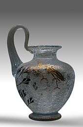
Since ancient times humans have been consciously aware of stress inside materials. Until the 17th century the understanding of stress was largely intuitive and empirical; and yet it resulted in some surprisingly sophisticated technology, like the composite bow and glass blowing.[1]
Over several millennia, architects and builders, in particular, learned how to put together carefully shaped wood beams and stone blocks to withstand, transmit, and distribute stress in the most effective manner, with ingenious devices such as the capitals, arches, cupolas, trusses and the flying buttresses of Gothic cathedrals.
Ancient and medieval architects did develop some geometrical methods and simple formulas to compute the proper sizes of pillars and beams, but the scientific understanding of stress became possible only after the necessary tools were invented in the 17th and 18th centuries: Galileo Galilei's rigorous experimental method, René Descartes's coordinates and analytic geometry, and Newton's laws of motion and equilibrium and calculus of infinitesimals.[2] With those tools, Augustin-Louis Cauchy was able to give the first rigorous and general mathematical model for stress in a homogeneous medium. Cauchy observed that the force across an imaginary surface was a linear function of its normal vector; and, moreover, that it must be a symmetric function (with zero total momentum).
The understanding of stress in liquids started with Newton, who provided a differential formula for friction forces (shear stress) in parallel laminar flow.
Overview
Definition
Stress is defined as the force across a "small" boundary per unit area of that boundary, for all orientations of the boundary.[3] Being derived from a fundamental physical quantity (force) and a purely geometrical quantity (area), stress is also a fundamental quantity, like velocity, torque or energy, that can be quantified and analyzed without explicit consideration of the nature of the material or of its physical causes.
Following the basic premises of continuum mechanics, stress is a macroscopic concept. Namely, the particles considered in its definition and analysis should be just small enough to be treated as homogeneous in composition and state, but still large enough to ignore quantum effects and the detailed motions of molecules. Thus, the force between two particles is actually the average of a very large number of atomic forces between their molecules; and physical quantities like mass, velocity, and forces that act through the bulk of three-dimensional bodies, like gravity, are assumed to be smoothly distributed over them.[4]:p.90–106 Depending on the context, one may also assume that the particles are large enough to allow the averaging out of other microscopic features, like the grains of a metal rod or the fibers of a piece of wood.

Quantitatively, the stress is expressed by the Cauchy traction vector T defined as the traction force F between adjacent parts of the material across an imaginary separating surface S, divided by the area of S.[5]:p.41–50 In a fluid at rest the force is perpendicular to the surface, and is the familiar pressure. In a solid, or in a flow of viscous liquid, the force F may not be perpendicular to S; hence the stress across a surface must be regarded a vector quantity, not a scalar. Moreover, the direction and magnitude generally depend on the orientation of S. Thus the stress state of the material must be described by a tensor, called the (Cauchy) stress tensor; which is a linear function that relates the normal vector n of a surface S to the stress T across S. With respect to any chosen coordinate system, the Cauchy stress tensor can be represented as a symmetric matrix of 3×3 real numbers. Even within a homogeneous body, the stress tensor may vary from place to place, and may change over time; therefore, the stress within a material is, in general, a time-varying tensor field.
Normal and shear stress
In general, the stress T that a particle P applies on another particle Q across a surface S can have any direction relative to S. The vector T may be regarded as the sum of two components: the normal stress (compression or tension) perpendicular to the surface, and the shear stress that is parallel to the surface.
If the normal unit vector n of the surface (pointing from Q towards P) is assumed fixed, the normal component can be expressed by a single number, the dot product T · n. This number will be positive if P is "pulling" on Q (tensile stress), and negative if P is "pushing" against Q (compressive stress) The shear component is then the vector T − (T · n)n.
Units
The dimension of stress is that of pressure, and therefore its coordinates are commonly measured in the same units as pressure: namely, pascals (Pa, that is, newtons per square metre) in the International System, or pounds per square inch (psi) in the Imperial system. Because mechanical stresses easily exceed a million Pascals, MPa, which stands for mega pascal, is a common unit of stress.The dimensional formula for stress is ML^-1T^-2
Causes and effects
Stress in a material body may be due to multiple physical causes, including external influences and internal physical processes. Some of these agents (like gravity, changes in temperature and phase, and electromagnetic fields) act on the bulk of the material, varying continuously with position and time. Other agents (like external loads and friction, ambient pressure, and contact forces) may create stresses and forces that are concentrated on certain surfaces, lines, or points; and possibly also on very short time intervals (as in the impulses due to collisions). In general, the stress distribution in the body is expressed as a piecewise continuous function of space and time.
Conversely, stress is usually correlated with various effects on the material, possibly including changes in physical properties like birefringence, polarization, and permeability. The imposition of stress by an external agent usually creates some strain (deformation) in the material, even if it is too small to be detected. In a solid material, such strain will in turn generate an internal elastic stress, analogous to the reaction force of a stretched spring, tending to restore the material to its original undeformed state. Fluid materials (liquids, gases and plasmas) by definition can only oppose deformations that would change their volume. However, if the deformation is changing with time, even in fluids there will usually be some viscous stress, opposing that change.
The relation between stress and its effects and causes, including deformation and rate of change of deformation, can be quite complicated (although a linear approximation may be adequate in practice if the quantities are small enough). Stress that exceeds certain strength limits of the material will result in permanent deformation (such as plastic flow, fracture, cavitation) or even change its crystal structure and chemical composition.
Simple stress
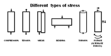
In some situations, the stress within a body may adequately be described by a single number, or by a single vector (a number and a direction). Three such simple stress situations, that are often encountered in engineering design, are the uniaxial normal stress, the simple shear stress, and the isotropic normal stress.[7]
Uniaxial normal stress

A common situation with a simple stress pattern is when a straight rod, with uniform material and cross section, is subjected to tension by opposite forces of magnitude along its axis. If the system is in equilibrium and not changing with time, and the weight of the bar can be neglected, then through each transversal section of the bar the top part must pull on the bottom part with the same force F. Therefore, the stress throughout the bar, across any horizontal surface, can be described by the number = F/A, where A is the area of the cross-section.


On the other hand, if one imagines the bar being cut along its length, parallel to the axis, there will be no force (hence no stress) between the two halves across the cut.
This type of stress may be called (simple) normal stress or uniaxial stress; specifically, (uniaxial, simple, etc.) tensile stress.[7] If the load is compression on the bar, rather than stretching it, the analysis is the same except that the force F and the stress change sign, and the stress is called compressive stress.
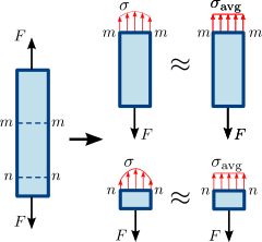

This analysis assumes the stress is evenly distributed over the entire cross-section. In practice, depending on how the bar is attached at the ends and how it was manufactured, this assumption may not be valid. In that case, the value = F/A will be only the average stress, called engineering stress or nominal stress. However, if the bar's length L is many times its diameter D, and it has no gross defects or built-in stress, then the stress can be assumed to be uniformly distributed over any cross-section that is more than a few times D from both ends. (This observation is known as the Saint-Venant's principle).
Normal stress occurs in many other situations besides axial tension and compression. If an elastic bar with uniform and symmetric cross-section is bent in one of its planes of symmetry, the resulting bending stress will still be normal (perpendicular to the cross-section), but will vary over the cross section: the outer part will be under tensile stress, while the inner part will be compressed. Another variant of normal stress is the hoop stress that occurs on the walls of a cylindrical pipe or vessel filled with pressurized fluid.
Simple shear stress
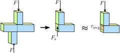
Another simple type of stress occurs when a uniformly thick layer of elastic material like glue or rubber is firmly attached to two stiff bodies that are pulled in opposite directions by forces parallel to the layer; or a section of a soft metal bar that is being cut by the jaws of a scissors-like tool. Let F be the magnitude of those forces, and M be the midplane of that layer. Just as in the normal stress case, the part of the layer on one side of M must pull the other part with the same force F. Assuming that the direction of the forces is known, the stress across M can be expressed by the single number = F/A, where F is the magnitude of those forces and A is the area of the layer.

However, unlike normal stress, this simple shear stress is directed parallel to the cross-section considered, rather than perpendicular to it.[7] For any plane S that is perpendicular to the layer, the net internal force across S, and hence the stress, will be zero.
As in the case of an axially loaded bar, in practice the shear stress may not be uniformly distributed over the layer; so, as before, the ratio F/A will only be an average ("nominal", "engineering") stress. However, that average is often sufficient for practical purposes.[8]:p.292 Shear stress is observed also when a cylindrical bar such as a shaft is subjected to opposite torques at its ends. In that case, the shear stress on each cross-section is parallel to the cross-section, but oriented tangentially relative to the axis, and increases with distance from the axis. Significant shear stress occurs in the middle plate (the "web") of I-beams under bending loads, due to the web constraining the end plates ("flanges").
Isotropic stress


Another simple type of stress occurs when the material body is under equal compression or tension in all directions. This is the case, for example, in a portion of liquid or gas at rest, whether enclosed in some container or as part of a larger mass of fluid; or inside a cube of elastic material that is being pressed or pulled on all six faces by equal perpendicular forces — provided, in both cases, that the material is homogeneous, without built-in stress, and that the effect of gravity and other external forces can be neglected.
In these situations, the stress across any imaginary internal surface turns out to be equal in magnitude and always directed perpendicularly to the surface independently of the surface's orientation. This type of stress may be called isotropic normal or just isotropic; if it is compressive, it is called hydrostatic pressure or just pressure. Gases by definition cannot withstand tensile stresses, but some liquids may withstand surprisingly large amounts of isotropic tensile stress under some circumstances. see Z-tube.
Cylinder stresses
Parts with rotational symmetry, such as wheels, axles, pipes, and pillars, are very common in engineering. Often the stress patterns that occur in such parts have rotational or even cylindrical symmetry. The analysis of such cylinder stresses can take advantage of the symmetry to reduce the dimension of the domain and/or of the stress tensor.
General stress
Often, mechanical bodies experience more than one type of stress at the same time; this is called combined stress. In normal and shear stress, the magnitude of the stress is maximum for surfaces that are perpendicular to a certain direction , and zero across any surfaces that are parallel to . When the shear stress is zero only across surfaces that are perpendicular to one particular direction, the stress is called biaxial, and can be viewed as the sum of two normal or shear stresses. In the most general case, called triaxial stress, the stress is nonzero across every surface element.

The Cauchy stress tensor

Combined stresses cannot be described by a single vector. Even if the material is stressed in the same way throughout the volume of the body, the stress across any imaginary surface will depend on the orientation of that surface, in a non-trivial way.
However, Cauchy observed that the stress vector across a surface will always be a linear function of the surface's normal vector , the unit-length vector that is perpendicular to it. That is, , where the function satisfies


for any vectors and any real numbers . The function , now called the (Cauchy) stress tensor, completely describes the stress state of a uniformly stressed body. (Today, any linear connection between two physical vector quantities is called a tensor, reflecting Cauchy's original use to describe the "tensions" (stresses) in a material.) In tensor calculus, is classified as second-order tensor of type (0,2).


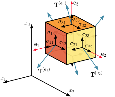
Like any linear map between vectors, the stress tensor can be represented in any chosen Cartesian coordinate system by a 3×3 matrix of real numbers. Depending on whether the coordinates are numbered or named , the matrix may be written as


- or


The stress vector across a surface with normal vector with coordinates is then a matrix product (where T in upper index is transposition) (look on Cauchy stress tensor), that is


The linear relation between and follows from the fundamental laws of conservation of linear momentum and static equilibrium of forces, and is therefore mathematically exact, for any material and any stress situation. The components of the Cauchy stress tensor at every point in a material satisfy the equilibrium equations (Cauchy’s equations of motion for zero acceleration). Moreover, the principle of conservation of angular momentum implies that the stress tensor is symmetric, that is , , and . Therefore, the stress state of the medium at any point and instant can be specified by only six independent parameters, rather than nine. These may be written


where the elements are called the orthogonal normal stresses (relative to the chosen coordinate system), and the orthogonal shear stresses.


Change of coordinates
The Cauchy stress tensor obeys the tensor transformation law under a change in the system of coordinates. A graphical representation of this transformation law is the Mohr's circle of stress distribution.
As a symmetric 3×3 real matrix, the stress tensor has three mutually orthogonal unit-length eigenvectors and three real eigenvalues , such that . Therefore, in a coordinate system with axes , the stress tensor is a diagonal matrix, and has only the three normal components the principal stresses. If the three eigenvalues are equal, the stress is an isotropic compression or tension, always perpendicular to any surface, there is no shear stress, and the tensor is a diagonal matrix in any coordinate frame.


Stress as a tensor field
In general, stress is not uniformly distributed over a material body, and may vary with time. Therefore, the stress tensor must be defined for each point and each moment, by considering an infinitesimal particle of the medium surrounding that point, and taking the average stresses in that particle as being the stresses at the point.
Stress in thin plates
Man-made objects are often made from stock plates of various materials by operations that do not change their essentially two-dimensional character, like cutting, drilling, gentle bending and welding along the edges. The description of stress in such bodies can be simplified by modeling those parts as two-dimensional surfaces rather than three-dimensional bodies.
In that view, one redefines a "particle" as being an infinitesimal patch of the plate's surface, so that the boundary between adjacent particles becomes an infinitesimal line element; both are implicitly extended in the third dimension, normal to (straight through) the plate. "Stress" is then redefined as being a measure of the internal forces between two adjacent "particles" across their common line element, divided by the length of that line. Some components of the stress tensor can be ignored, but since particles are not infinitesimal in the third dimension one can no longer ignore the torque that a particle applies on its neighbors. That torque is modeled as a bending stress that tends to change the curvature of the plate. However, these simplifications may not hold at welds, at sharp bends and creases (where the radius of curvature is comparable to the thickness of the plate).
Stress in thin beams

The analysis of stress can be considerably simplified also for thin bars, beams or wires of uniform (or smoothly varying) composition and cross-section that are subjected to moderate bending and twisting. For those bodies, one may consider only cross-sections that are perpendicular to the bar's axis, and redefine a "particle" as being a piece of wire with infinitesimal length between two such cross sections. The ordinary stress is then reduced to a scalar (tension or compression of the bar), but one must take into account also a bending stress (that tries to change the bar's curvature, in some direction perpendicular to the axis) and a torsional stress (that tries to twist or un-twist it about its axis).
Other descriptions of stress
The Cauchy stress tensor is used for stress analysis of material bodies experiencing small deformations where the differences in stress distribution in most cases can be neglected. For large deformations, also called finite deformations, other measures of stress, such as the first and second Piola–Kirchhoff stress tensors, the Biot stress tensor, and the Kirchhoff stress tensor, are required.
Solids, liquids, and gases have stress fields. Static fluids support normal stress but will flow under shear stress. Moving viscous fluids can support shear stress (dynamic pressure). Solids can support both shear and normal stress, with ductile materials failing under shear and brittle materials failing under normal stress. All materials have temperature dependent variations in stress-related properties, and non-Newtonian materials have rate-dependent variations.
Stress analysis
Stress analysis is a branch of applied physics that covers the determination of the internal distribution of internal forces in solid objects. It is an essential tool in engineering for the study and design of structures such as tunnels, dams, mechanical parts, and structural frames, under prescribed or expected loads. It is also important in many other disciplines; for example, in geology, to study phenomena like plate tectonics, vulcanism and avalanches; and in biology, to understand the anatomy of living beings.
Goals and assumptions
Stress analysis is generally concerned with objects and structures that can be assumed to be in macroscopic static equilibrium. By Newton's laws of motion, any external forces are being applied to such a system must be balanced by internal reaction forces,[9]:p.97 which are almost always surface contact forces between adjacent particles — that is, as stress.[5] Since every particle needs to be in equilibrium, this reaction stress will generally propagate from particle, creating a stress distribution throughout the body.
The typical problem in stress analysis is to determine these internal stresses, given the external forces that are acting on the system. The latter may be body forces (such as gravity or magnetic attraction), that act throughout the volume of a material;[10]:p.42–81 or concentrated loads (such as friction between an axle and a bearing, or the weight of a train wheel on a rail), that are imagined to act over a two-dimensional area, or along a line, or at single point.
In stress analysis one normally disregards the physical causes of the forces or the precise nature of the materials. Instead, one assumes that the stresses are related to deformation (and, in non-static problems, to the rate of deformation) of the material by known constitutive equations.[11]
Methods
Stress analysis may be carried out experimentally, by applying loads to the actual artifact or to scale model, and measuring the resulting stresses, by any of several available methods. This approach is often used for safety certification and monitoring. However, most stress analysis is done by mathematical methods, especially during design.
The basic stress analysis problem can be formulated by Euler's equations of motion for continuous bodies (which are consequences of Newton's laws for conservation of linear momentum and angular momentum) and the Euler-Cauchy stress principle, together with the appropriate constitutive equations. Thus one obtains a system of partial differential equations involving the stress tensor field and the strain tensor field, as unknown functions to be determined. The external body forces appear as the independent ("right-hand side") term in the differential equations, while the concentrated forces appear as boundary conditions. The basic stress analysis problem is therefore a boundary-value problem.
Stress analysis for elastic structures is based on the theory of elasticity and infinitesimal strain theory. When the applied loads cause permanent deformation, one must use more complicated constitutive equations, that can account for the physical processes involved (plastic flow, fracture, phase change, etc.).
However, engineered structures are usually designed so that the maximum expected stresses are well within the range of linear elasticity (the generalization of Hooke’s law for continuous media); that is, the deformations caused by internal stresses are linearly related to them. In this case the differential equations that define the stress tensor are linear, and the problem becomes much easier. For one thing, the stress at any point will be a linear function of the loads, too. For small enough stresses, even non-linear systems can usually be assumed to be linear.
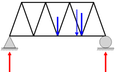
Stress analysis is simplified when the physical dimensions and the distribution of loads allow the structure to be treated as one- or two-dimensional. In the analysis of trusses, for example, the stress field may be assumed to be uniform and uniaxial over each member. Then the differential equations reduce to a finite set of equations (usually linear) with finitely many unknowns. In other contexts one may be able to reduce the three-dimensional problem to a two-dimensional one, and/or replace the general stress and strain tensors by simpler models like uniaxial tension/compression, simple shear, etc.
Still, for two- or three-dimensional cases one must solve a partial differential equation problem. Analytical or closed-form solutions to the differential equations can be obtained when the geometry, constitutive relations, and boundary conditions are simple enough. Otherwise one must generally resort to numerical approximations such as the finite element method, the finite difference method, and the boundary element method.
Alternative measures of stress
Other useful stress measures include the first and second Piola–Kirchhoff stress tensors, the Biot stress tensor, and the Kirchhoff stress tensor.
Piola–Kirchhoff stress tensor
In the case of finite deformations, the Piola–Kirchhoff stress tensors express the stress relative to the reference configuration. This is in contrast to the Cauchy stress tensor which expresses the stress relative to the present configuration. For infinitesimal deformations and rotations, the Cauchy and Piola–Kirchhoff tensors are identical.
Whereas the Cauchy stress tensor relates stresses in the current configuration, the deformation gradient and strain tensors are described by relating the motion to the reference configuration; thus not all tensors describing the state of the material are in either the reference or current configuration. Describing the stress, strain and deformation either in the reference or current configuration would make it easier to define constitutive models (for example, the Cauchy Stress tensor is variant to a pure rotation, while the deformation strain tensor is invariant; thus creating problems in defining a constitutive model that relates a varying tensor, in terms of an invariant one during pure rotation; as by definition constitutive models have to be invariant to pure rotations). The 1st Piola–Kirchhoff stress tensor, is one possible solution to this problem. It defines a family of tensors, which describe the configuration of the body in either the current or the reference state.

The 1st Piola–Kirchhoff stress tensor, relates forces in the present configuration with areas in the reference ("material") configuration.

where is the deformation gradient and is the Jacobian determinant.


In terms of components with respect to an orthonormal basis, the first Piola–Kirchhoff stress is given by

Because it relates different coordinate systems, the 1st Piola–Kirchhoff stress is a two-point tensor. In general, it is not symmetric. The 1st Piola–Kirchhoff stress is the 3D generalization of the 1D concept of engineering stress.
If the material rotates without a change in stress state (rigid rotation), the components of the 1st Piola–Kirchhoff stress tensor will vary with material orientation.
The 1st Piola–Kirchhoff stress is energy conjugate to the deformation gradient.
2nd Piola–Kirchhoff stress tensor
Whereas the 1st Piola–Kirchhoff stress relates forces in the current configuration to areas in the reference configuration, the 2nd Piola–Kirchhoff stress tensor relates forces in the reference configuration to areas in the reference configuration. The force in the reference configuration is obtained via a mapping that preserves the relative relationship between the force direction and the area normal in the reference configuration.


In index notation with respect to an orthonormal basis,

This tensor, a one-point tensor, is symmetric.
If the material rotates without a change in stress state (rigid rotation), the components of the 2nd Piola–Kirchhoff stress tensor remain constant, irrespective of material orientation.
The 2nd Piola–Kirchhoff stress tensor is energy conjugate to the Green–Lagrange finite strain tensor.
See also
| Continuum mechanics | ||||
|---|---|---|---|---|
 | ||||
|
Laws
|
||||
- Bending
- Compressive strength
- Kelvin probe force microscope
- Mohr's circle
- Residual stress
- Shear strength
- Shot peening
- Strain
- Strain tensor
- Strain rate tensor
- Stress–energy tensor
- Stress–strain curve
- Stress concentration
- Transient friction loading
- Tensile strength
- Virial stress
- Yield (engineering)
- Yield stress
- Yield surface
- Virial theorem
Further reading
- Chakrabarty, J. (2006). Theory of plasticity (3 ed.). Butterworth-Heinemann. pp. 17–32. ISBN 0-7506-6638-2.
- Beer, Ferdinand Pierre; Elwood Russell Johnston; John T. DeWolf (1992). Mechanics of Materials. McGraw-Hill Professional. ISBN 0-07-112939-1.
- Brady, B.H.G.; E.T. Brown (1993). Rock Mechanics For Underground Mining (Third ed.). Kluwer Academic Publisher. pp. 17–29. ISBN 0-412-47550-2.
- Chen, Wai-Fah; Baladi, G.Y. (1985). Soil Plasticity, Theory and Implementation. ISBN 0-444-42455-5.
- Chou, Pei Chi; Pagano, N.J. (1992). Elasticity: tensor, dyadic, and engineering approaches. Dover books on engineering. Dover Publications. pp. 1–33. ISBN 0-486-66958-0.
- Davis, R. O.; Selvadurai. A. P. S. (1996). Elasticity and geomechanics. Cambridge University Press. pp. 16–26. ISBN 0-521-49827-9.
- Dieter, G. E. (3 ed.). (1989). Mechanical Metallurgy. New York: McGraw-Hill. ISBN 0-07-100406-8.
- Holtz, Robert D.; Kovacs, William D. (1981). An introduction to geotechnical engineering. Prentice-Hall civil engineering and engineering mechanics series. Prentice-Hall. ISBN 0-13-484394-0.
- Jones, Robert Millard (2008). Deformation Theory of Plasticity. Bull Ridge Corporation. pp. 95–112. ISBN 0-9787223-1-0.
- Jumikis, Alfreds R. (1969). Theoretical soil mechanics: with practical applications to soil mechanics and foundation engineering. Van Nostrand Reinhold Co. ISBN 0-442-04199-3.
- Landau, L.D. and E.M.Lifshitz. (1959). Theory of Elasticity.
- Love, A. E. H. (4 ed.). (1944). Treatise on the Mathematical Theory of Elasticity. New York: Dover Publications. ISBN 0-486-60174-9.
- Marsden, J. E.; Hughes, T. J. R. (1994). Mathematical Foundations of Elasticity. Dover Publications. pp. 132–142. ISBN 0-486-67865-2.
- Parry, Richard Hawley Grey (2004). Mohr circles, stress paths and geotechnics (2 ed.). Taylor & Francis. pp. 1–30. ISBN 0-415-27297-1.
- Rees, David (2006). Basic Engineering Plasticity – An Introduction with Engineering and Manufacturing Applications. Butterworth-Heinemann. pp. 1–32. ISBN 0-7506-8025-3.
- Timoshenko, Stephen P.; James Norman Goodier (1970). Theory of Elasticity (Third ed.). McGraw-Hill International Editions. ISBN 0-07-085805-5.
- Timoshenko, Stephen P. (1983). History of strength of materials: with a brief account of the history of theory of elasticity and theory of structures. Dover Books on Physics. Dover Publications. ISBN 0-486-61187-6.
References
- ↑ Gordon, J.E. (2003). Structures, or, Why things don't fall down (2. Da Capo Press ed.). Cambridge, MA: Da Capo Press. ISBN 0306812835.
- ↑ Jacob Lubliner (2008). "Plasticity Theory" (revised edition). Dover Publications. ISBN 0-486-46290-0
- ↑ Wai-Fah Chen and Da-Jian Han (2007), "Plasticity for Structural Engineers". J. Ross Publishing ISBN 1-932159-75-4
- ↑ Peter Chadwick (1999), "Continuum Mechanics: Concise Theory and Problems". Dover Publications, series "Books on Physics". ISBN 0-486-40180-4. pages
- 1 2 I-Shih Liu (2002), "Continuum Mechanics". Springer ISBN 3-540-43019-9
- ↑ (2009) The art of making glass. Lamberts Glashütte (LambertsGlas) product brochure. Accessed on 2013-02-08.
- 1 2 3 Ronald L. Huston and Harold Josephs (2009), "Practical Stress Analysis in Engineering Design". 3rd edition, CRC Press, 634 pages. ISBN 9781574447132
- ↑ Walter D. Pilkey, Orrin H. Pilkey (1974), "Mechanics of solids" (book)
- ↑ Donald Ray Smith and Clifford Truesdell (1993) "An Introduction to Continuum Mechanics after Truesdell and Noll". Springer. ISBN 0-7923-2454-4
- ↑ Fridtjov Irgens (2008), "Continuum Mechanics". Springer. ISBN 3-540-74297-2
- ↑ Slaughter