Electronic filter
Electronic filters are circuits which perform signal processing functions, specifically to remove unwanted frequency components from the signal, to enhance wanted ones, or both. Electronic filters can be:
- passive or active
- analog or digital
- high-pass, low-pass, band-pass, band-stop (band-rejection; notch), or all-pass.
- discrete-time (sampled) or continuous-time
- linear or non-linear
- infinite impulse response (IIR type) or finite impulse response (FIR type)
The most common types of electronic filters are linear filters, regardless of other aspects of their design. See the article on linear filters for details on their design and analysis.
History
The oldest forms of electronic filters are passive analog linear filters, constructed using only resistors and capacitors or resistors and inductors. These are known as RC and RL single-pole filters respectively. More complex multipole LC filters have also existed for many years, and their operation is well understood.
Hybrid filters are also possible, typically involving a combination of analog amplifiers with mechanical resonators or delay lines. Other devices such as CCD delay lines have also been used as discrete-time filters. With the availability of digital signal processing, active digital filters have become common.
Classification by technology
Passive filters
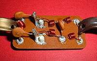
Passive implementations of linear filters are based on combinations of resistors (R), inductors (L) and capacitors (C). These types are collectively known as passive filters, because they do not depend upon an external power supply and/or they do not contain active components such as transistors.
Inductors block high-frequency signals and conduct low-frequency signals, while capacitors do the reverse. A filter in which the signal passes through an inductor, or in which a capacitor provides a path to ground, presents less attenuation to low-frequency signals than high-frequency signals and is therefore a low-pass filter. If the signal passes through a capacitor, or has a path to ground through an inductor, then the filter presents less attenuation to high-frequency signals than low-frequency signals and therefore is a high-pass filter. Resistors on their own have no frequency-selective properties, but are added to inductors and capacitors to determine the time-constants of the circuit, and therefore the frequencies to which it responds.
The inductors and capacitors are the reactive elements of the filter. The number of elements determines the order of the filter. In this context, an LC tuned circuit being used in a band-pass or band-stop filter is considered a single element even though it consists of two components.
At high frequencies (above about 100 megahertz), sometimes the inductors consist of single loops or strips of sheet metal, and the capacitors consist of adjacent strips of metal. These inductive or capacitive pieces of metal are called stubs.
Single element types

The simplest passive filters, RC and RL filters, include only one reactive element, except hybrid LC filter which is characterized by inductance and capacitance integrated in one element.[1]
L filter
An L filter consists of two reactive elements, one in series and one in parallel.
T and π filters


Three-element filters can have a 'T' or 'π' topology and in either geometries, a low-pass, high-pass, band-pass, or band-stop characteristic is possible. The components can be chosen symmetric or not, depending on the required frequency characteristics. The high-pass T filter in the illustration, has a very low impedance at high frequencies, and a very high impedance at low frequencies. That means that it can be inserted in a transmission line, resulting in the high frequencies being passed and low frequencies being reflected. Likewise, for the illustrated low-pass π filter, the circuit can be connected to a transmission line, transmitting low frequencies and reflecting high frequencies. Using m-derived filter sections with correct termination impedances, the input impedance can be reasonably constant in the pass band.[2]
Multiple element types
Multiple element filters are usually constructed as a ladder network. These can be seen as a continuation of the L,T and π designs of filters. More elements are needed when it is desired to improve some parameter of the filter such as stop-band rejection or slope of transition from pass-band to stop-band.
Active filters
Active filters are implemented using a combination of passive and active (amplifying) components, and require an outside power source. Operational amplifiers are frequently used in active filter designs. These can have high Q factor, and can achieve resonance without the use of inductors. However, their upper frequency limit is limited by the bandwidth of the amplifiers.
Other filter technologies
Digital filters
Digital signal processing allows the inexpensive construction of a wide variety of filters. The signal is sampled and an analog-to-digital converter turns the signal into a stream of numbers. A computer program running on a CPU or a specialized DSP (or less often running on a hardware implementation of the algorithm) calculates an output number stream. This output can be converted to a signal by passing it through a digital-to-analog converter. There are problems with noise introduced by the conversions, but these can be controlled and limited for many useful filters. Due to the sampling involved, the input signal must be of limited frequency content or aliasing will occur.
Quartz filters and piezoelectrics
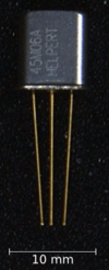
In the late 1930s, engineers realized that small mechanical systems made of rigid materials such as quartz would acoustically resonate at radio frequencies, i.e. from audible frequencies (sound) up to several hundred megahertz. Some early resonators were made of steel, but quartz quickly became favored. The biggest advantage of quartz is that it is piezoelectric. This means that quartz resonators can directly convert their own mechanical motion into electrical signals. Quartz also has a very low coefficient of thermal expansion which means that quartz resonators can produce stable frequencies over a wide temperature range. Quartz crystal filters have much higher quality factors than LCR filters. When higher stabilities are required, the crystals and their driving circuits may be mounted in a "crystal oven" to control the temperature. For very narrow band filters, sometimes several crystals are operated in series.
Engineers realized that a large number of crystals could be collapsed into a single component, by mounting comb-shaped evaporations of metal on a quartz crystal. In this scheme, a "tapped delay line" reinforces the desired frequencies as the sound waves flow across the surface of the quartz crystal. The tapped delay line has become a general scheme of making high-Q filters in many different ways.
SAW filters
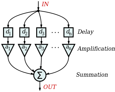
SAW (surface acoustic wave) filters are electromechanical devices commonly used in radio frequency applications. Electrical signals are converted to a mechanical wave in a device constructed of a piezoelectric crystal or ceramic; this wave is delayed as it propagates across the device, before being converted back to an electrical signal by further electrodes. The delayed outputs are recombined to produce a direct analog implementation of a finite impulse response filter. This hybrid filtering technique is also found in an analog sampled filter. SAW filters are limited to frequencies up to 3 GHz. The filters were developed by Professor Ted Paige and others.[3]
BAW filters
BAW (bulk acoustic wave) filters are electromechanical devices. BAW filters can implement ladder or lattice filters. BAW filters typically operate at frequencies from around 2 to around 16 GHz, and may be smaller or thinner than equivalent SAW filters. Two main variants of BAW filters are making their way into devices: thin-film bulk acoustic resonator or FBAR and solid mounted bulk acoustic resonators.
Garnet filters
Another method of filtering, at microwave frequencies from 800 MHz to about 5 GHz, is to use a synthetic single crystal yttrium iron garnet sphere made of a chemical combination of yttrium and iron (YIGF, or yttrium iron garnet filter). The garnet sits on a strip of metal driven by a transistor, and a small loop antenna touches the top of the sphere. An electromagnet changes the frequency that the garnet will pass. The advantage of this method is that the garnet can be tuned over a very wide frequency by varying the strength of the magnetic field.
Atomic filters
For even higher frequencies and greater precision, the vibrations of atoms must be used. Atomic clocks use caesium masers as ultra-high Q filters to stabilize their primary oscillators. Another method, used at high, fixed frequencies with very weak radio signals, is to use a ruby maser tapped delay line.
The transfer function
- see also Filter (signal processing) for further analysis
The transfer function of a filter is the ratio of the output signal to that of the input signal as a function of the complex frequency :


with .

The transfer function of all linear time-invariant filters, when constructed of discrete components, will be the ratio of two polynomials in , i.e. a rational function of . The order of the transfer function will be the highest power of encountered in either the numerator or the denominator.
Classification by topology
Electronic filters can be classified by the technology used to implement them. Filters using passive filter and active filter technology can be further classified by the particular electronic filter topology used to implement them.
Any given filter transfer function may be implemented in any electronic filter topology.
Some common circuit topologies are:
- Cauer topology – passive
- Sallen–Key topology – active
- Multiple Feedback topology – active
- State Variable Topology – active
- Biquadratic topology biquad filter – active
Classification by design methodology
| Linear analog electronic filters |
|---|
|
|
Simple filters |
Historically, linear analog filter design has evolved through three major approaches. The oldest designs are simple circuits where the main design criterion was the Q factor of the circuit. This reflected the radio receiver application of filtering as Q was a measure of the frequency selectivity of a tuning circuit. From the 1920s filters began to be designed from the image point of view, mostly being driven by the requirements of telecommunications. After World War II the dominant methodology was network synthesis. The higher mathematics used originally required extensive tables of polynomial coefficient values to be published but modern computer resources have made that unnecessary.[4]
Direct circuit analysis
Low order filters can be designed by directly applying basic circuit laws such as Kirchhoff's laws to obtain the transfer function. This kind of analysis is usually only carried out for simple filters of 1st or 2nd order.
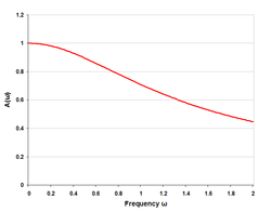
Image impedance analysis
- Main article: Composite image filters
This approach analyses the filter sections from the point of view of the filter being in an infinite chain of identical sections. It has the advantages of simplicity of approach and the ability to easily extend to higher orders. It has the disadvantage that accuracy of predicted responses relies on filter terminations in the image impedance, which is usually not the case.[5]

Network synthesis
- Main article: Network synthesis filters
The network synthesis approach starts with a required transfer function and then expresses that as a polynomial equation of the input impedance of the filter. The actual element values of the filter are obtained by continued-fraction or partial-fraction expansions of this polynomial. Unlike the image method, there is no need for impedance matching networks at the terminations as the effects of the terminating resistors are included in the analysis from the start.[5]
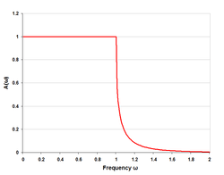
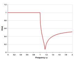
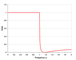
Here is an image comparing Butterworth, Chebyshev, and elliptic filters. The filters in this illustration are all fifth-order low-pass filters. The particular implementation – analog or digital, passive or active – makes no difference; their output would be the same.
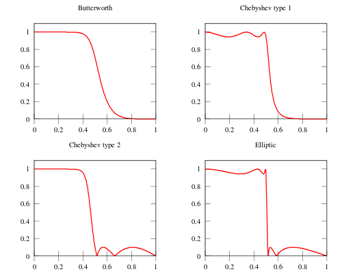
As is clear from the image, elliptic filters are sharper than all the others, but they show ripples on the whole bandwidth.
See also
Notes, references and external links
| Wikimedia Commons has media related to Electronic filters. |
- ↑ Dzhankhotov V., Hybrid LC filter for power electronic drives: Theory and Implementation, 2009
- ↑ The American Radio Relay League, Inc.: "The ARRL Handbook, 1968" page 50
- ↑ Ash, Eric A; E. Peter Raynes (December 2009). "Edward George Sydney Paige. 18 July 1930 — 20 February 2004" (PDF). Biographical Memoirs of Fellows of the Royal Society. 55: 185–200. doi:10.1098/rsbm.2009.0009.
- ↑ Bray, J, Innovation and the Communications Revolution, Institute of Electrical Engineers
- 1 2 Matthaei, Young, Jones Microwave Filters, Impedance-Matching Networks, and Coupling Structures McGraw-Hill 1964
- Zverev, Anatol, I (1969). Handbook of Filter Synthesis. John Wiley & Sons. ISBN 0-471-98680-1. Catalog of passive filter types and component values. The Bible for practical electronic filter design.
- Williams, Arthur B; Taylor, Fred J (1995). Electronic Filter Design Handbook. McGraw-Hill. ISBN 0-07-070441-4.
- National Semiconductor AN-779 (TI SNOA224a) application note describing analog filter theory
- Fundamentals of Electrical Engineering and Electronics – Detailed explanation of all types of filters
- BAW filters (in French; PDF)
- Some Interesting Filter Design Configurations & Transformations
- Analog Filters for Data Conversion