Single-carrier FDMA
| Passband modulation |
|---|
| Analog modulation |
| Digital modulation |
| Spread spectrum |
| See also |
SC-FDMA has drawn great attention as an attractive alternative to OFDMA, especially in the uplink communications where lower peak-to-average power ratio (PAPR) greatly benefits the mobile terminal in terms of transmit power efficiency and reduced cost of the power amplifier. It has been adopted as the uplink multiple access scheme in 3GPP Long Term Evolution (LTE), or Evolved UTRA (E-UTRA).[1][2][3]
The performance of SC-FDMA in relation to OFDMA has been the subject of various studies.[4][5][6] Although the performance gap is small, SC-FDMA's advantage of low PAPR makes it desirable for uplink wireless transmission in mobile communication systems, where transmitter power efficiency is of paramount importance.
Transmitter and Receiver Structure of LP-OFDMA/SC-FDMA
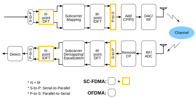
The transmission processing of SC-FDMA is very similar to that of OFDMA. For each user, the sequence of bits transmitted is mapped to a complex constellation of symbols (BPSK, QPSK or M-Quadrature amplitude modulation). Then different transmitters (users) are assigned different Fourier coefficients. This assignment is carried out in the mapping and demapping blocks. The receiver side includes one demapping block, one IDFT block, and one detection block for each user signal to be received. Just like in OFDM, guard intervals (called cyclic prefixes) with cyclic repetition are introduced between blocks of symbols in view to efficiently eliminate inter-symbol interference from time spreading (caused by multi-path propagation) among the blocks.
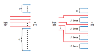
In SC-FDMA, multiple access among users is made possible by assigning different users different sets of non-overlapping Fourier coefficients (sub-carriers). This is achieved at the transmitter by inserting (prior to IDFT) silent Fourier coefficients (at positions assigned to other users), and removing them on the receiver side after the DFT.

The distinguishing feature of SC-FDMA is that it leads to a single-carrier transmit signal, in contrast to OFDMA which is a multi-carrier transmission scheme. Subcarrier mapping can be classified into two types: localized mapping and distributed mapping. In localized mapping, the DFT outputs are mapped to a subset of consecutive subcarriers, thereby confining them to only a fraction of the system bandwidth. In distributed mapping, the DFT outputs of the input data are assigned to subcarriers over the entire bandwidth non-continuously, resulting in zero amplitude for the remaining subcarriers. A special case of distributed SC-FDMA is called interleaved SC-FDMA (IFDMA), where the occupied subcarriers are equally spaced over the entire bandwidth.[7]
Owing to its inherent single carrier structure, a prominent advantage of SC-FDMA over OFDM and OFDMA is that its transmit signal has a lower peak-to-average power ratio (PAPR), resulting in relaxed design parameters in the transmit path of a subscriber unit. Intuitively, the reason lies in the fact that where OFDM transmit symbols directly modulate multiple sub-carriers, SC-FDMA transmit symbols are first processed by an N-point DFT block.[8]
In OFDM, as well as SC-FDMA, equalization is achieved on the receiver side, after the DFT calculation, by multiplying each Fourier coefficient by a complex number. Thus, frequency-selective fading and phase distortion can be easily counteracted. The advantage is that frequency domain equalization using FFTs requires less computation than conventional time-domain equalization.
A related concept is the combination of a single carrier transmission with the single-carrier frequency-domain-equalization (SC-FDE) scheme. [9] The single carrier transmission, unlike SC-FDMA and OFDM, employs no IDFT or DFT at the transmitter, but introduces the cyclic prefix to transform the linear channel convolution into a circular one. After removing the cyclic prefix at the receiver, a DFT is applied to arrive in the frequency domain, where a simple single-carrier frequency-domain-equalization (SC-FDE) scheme can be employed, followed by the IDFT operation.

- DFT: Discrete Fourier Transform
- IDFT: Inverse Discrete Fourier Transform
- CP: Cyclic Prefix
- PS: Pulse Shaping
- DAC: Digital to analog Conversion
- RF: Radio Frequency signal
- ADC: Analog to Digital Conversion
- LP-OFDMA: Linearly precoded OFDMA
Useful properties
- Low PAPR (Crest Factor)
- Low sensitivity to carrier frequency offset
- Less sensitive to non-linear distortion and hence, it allows the use of low-cost power amplifiers
- Greater robustness against spectral nulls
See also
References
- ↑ Hyung G. Myung, Junsung Lim, and David J. Goodman, “Single Carrier FDMA for Uplink Wireless Transmission”, IEEE Vehicular Technology Magazine, vol. 1, no. 3, Sep. 2006, pp. 30–38
- ↑ H. Ekström, A. Furuskär, J. Karlsson, M. Meyer, S. Parkvall, J. Torsner, and M. Wahlqvist, “Technical Solutions for the 3G Long-Term Evolution,” IEEE Commun. Mag., vol. 44, no. 3, March 2006, pp. 38–45
- ↑ 3rd Generation Partnership Project (3GPP); Technical Specification Group Radio Access Network; Physical Layer Aspects for Evolved UTRA, http://www.3gpp.org/ftp/Specs/html-info/25814.htm
- ↑ M. Danish Nisar, Hans Nottensteiner, and Thomas Hindelang, “On Performance Limits of DFT-Spread OFDM Systems”, in Sixteenth IST Mobile Summit, July 2007 in Budapest, Hungary.
- ↑ B.E. Priyanto, H. Codina, S. Rene, T.B. Sorensen, P. Mogensen, “Initial Performance Evaluation of DFT-Spread OFDM Based SC-FDMA for UTRA LTE Uplink”, IEEE Vehicular Technology Conference (VTC) 2007 Spring, Dublin, Ireland, Apr. 2007
- ↑ N. Benvenuto and S. Tomasin, “On the comparison between OFDM and single carrier modulation with a DFE using a frequency domain feedforward filter,” IEEE Trans. on Commun., vol. 50, no. 6, June 2002 pp. 947–955
- ↑ Xixia Leader in Converged IP Testing, "Single Carrier FDMA in LTE", 915-2725-01 Rev A November 2009.
- ↑ H. G. Myung, J. Lim, and D. J. Goodman, "Peak-to-Average Power Ratio of Single Carrier FDMA Signals with Pulse Shaping", The 17th Annual IEEE International Symposium on Personal, Indoor and Mobile Radio Communications (PIMRC ’06), Helsinki, Finland, Sep. 2006
- ↑ D. Falconer, S. L. Ariyavisitakul, A. Benyamin-Seeyar, and B. Eidson, “Frequency Domain Equalization for Single-Carrier Broadband Wireless Systems,” IEEE Commun. Mag., vol. 40, no. 4, April 2002, pp. 58–66