Varicap
 Internal structure of a varicap | |
| Type | Passive |
|---|---|
| Pin configuration | anode and cathode |
| Electronic symbol | |
 | |
In electronics, a varicap diode, varactor diode, variable capacitance diode, variable reactance diode or tuning diode is a type of diode designed to exploit the voltage-dependent capacitance of a reversed-biased p–n junction.
Applications
Varactors are used as voltage-controlled capacitors. They are commonly used in voltage-controlled oscillators, parametric amplifiers, and frequency multipliers. Voltage-controlled oscillators have many applications such as frequency modulation for FM transmitters and phase-locked loops. Phase-locked loops are used for the frequency synthesizers that tune many radios, television sets, and cellular telephones.
The varicap was developed by the Pacific Semiconductor subsidiary of the Ramo Wooldridge Corporation who received a patent for the device in June 1961.[1] The device name was also trademarked as the "Varicap" by TRW Semiconductors, the successor to Pacific Semiconductors, in October 1967. This helps explain the different names for the device as it came into use.
Operation

Varactors are operated in a reverse-biased state, so no DC current flows through the device. The amount of reverse bias controls the thickness of the depletion zone and therefore the varactor's junction capacitance. Generally, the depletion region thickness is proportional to the square root of the applied voltage, and capacitance is inversely proportional to the depletion region thickness. Thus, the capacitance is inversely proportional to the square root of applied voltage.
All diodes exhibit this variable junction capacitance, but varactors are manufactured to exploit the effect and increase the capacitance variation.
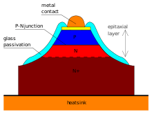
The figure shows an example of a cross section of a varactor with the depletion layer formed of a p–n junction. This depletion layer can also be made of a MOS or a Schottky diode. This is important in CMOS and MMIC technology.
Use in a circuit
Tuning circuits
Generally the use of a varicap diode in a circuit requires connecting it to a tuned circuit, usually in parallel with any existing capacitance or inductance.[2] Because a DC voltage must be applied reverse bias across the varicap to alter its capacitance, this must be blocked from entering the tuned circuit. This is accomplished by placing a DC blocking capacitor with a capacitance about 100 times greater than the maximum capacitance of the varicap diode in series with it and applying the DC from a high impedance source to the node between the varicap cathode and the blocking capacitor as shown in the upper left hand diagram, right.

Since no significant DC current flows in the varicap, the value of the resistor connecting its cathode back to the DC control voltage can be somewhere in the range of 22 kΩ to 150 kΩ and the blocking capacitor somewhere in the range of 5-100 nF. Sometimes, with very high-Q tuned circuits, an inductor is placed in series with the resistor to increase the source impedance of the control voltage so as not to load the tuned circuit and decrease its Q.
A second circuit using two back-to-back (anode-to-anode), series-connected varicap diodes (shown lower-left in the image) is another common configuration. The second varicap effectively replaces the blocking capacitor in the first circuit. This reduces the overall capacitance and the capacitance range by half, but possesses the advantage of reducing the AC component of voltage across each device and symmetrical distortion should the AC component possess enough amplitude to bias the varicaps into forward conduction.
When designing tuning circuits with varicaps it is usually good practice to maintain the AC component of voltage across the varicap at a minimal level, usually less than 100 mV peak to peak, to prevent this changing the capacitance of the diode too much and thus distorting the signal and adding harmonics to it.
One remaining circuit, right, depicts two series connected varicaps being used in a circuit with separate DC and AC signal ground connections. The DC ground being depicted as the traditional ground symbol, and the AC ground being depicted as a triangle. Separation of grounds is often done to prevent high-frequency radiation from the low-frequency ground node or DC currents in the AC ground node upsetting biasing and operating points of active devices such as varicaps and transistors.
These circuit configurations are quite common in television tuners and electronically tuned broadcast AM and FM receivers, as well as other communications equipment and industrial equipment. Early varicap diodes usually required a reverse voltage range of 0–33 v to obtain capacitance range, which was quite small, approximately 1–10 pF. These types were and are still extensively used in television tuners, whose high carrier frequencies require only small changes in capacitance.
In time, varicap diodes were developed which exhibited very large capacitance ranges, 100–500 pF, with relatively small changes in reverse bias: 0–5 or 0–12 v. These newer devices allow electronically tuned AM broadcast receivers to be realized as well as a multitude of other functions requiring large capacitance changes at lower frequencies, generally below 10 MHz. Some of designs of electronic security tag readers used in retail outlets require these high capacitance varicaps in their voltage-controlled oscillators.


The three leaded devices depicted at the top of the page are generally two common cathode connected varicaps in a single package. In the consumer AM/FM tuner depicted at the right, a single dual-package varicap diode adjusts both the passband of the tank circuit (the main station selector), and the local oscillator with a single varicap for each. This is done to keep costs down – two dual packages could have been used, one for the tank and one for the oscillator, four diodes in all, and this was what was depicted in the application data for the LA1851N AM radio chip. Two lower-capacitance dual varactors are used in the FM section which operates at a frequency about one hundred time greater and are highlighted by red arrows. In this case four diodes are used, one dual package each for the tank/bandpass filter and the local oscillator.
Switching
Special types of varicap diode exhibiting an abrupt change in capacitance can often be found in consumer equipment such as television tuners, which are used to switch radio frequency signal paths. When in the high capacitance state, usually with low or no bias, they present a low impedance path to RF, whereas when reverse biased their capacitance abruptly decreases and their RF impedance increases. Although they are still slightly conductive to the RF path, the attenuation they introduce decreases the unwanted signal to an acceptably low level. They are often used in pairs to switch between two different RF sources such as the VHF and UHF bands in a television tuner by supplying them with complementary bias voltages. The fourth device from the left in the picture at the head of this page is one such device.
Harmonic multiplication
In some applications, such as harmonic multiplication, a large signal amplitude alternating voltage is applied across a varicap to deliberately vary the capacitance at signal rate to generate higher harmonics, which are extracted through filtering. If a sine wave current of sufficient amplitude is applied driven through a varicap, the resultant voltage gets "peaked" into a more triangular shape, and odd harmonics are generated.
This was one early method used to generate microwave frequencies of moderate power, 1–2 GHz at 1–5 watts, from about 20 watts at a frequency of 3–400 MHz before adequate transistors had been developed to operate at this higher frequency. This technique is still used to generate much higher frequencies, in the 100 GHz – 1 THz range, where even the fastest GaAs transistors are still inadequate.
Substitutes for varicap diodes
Experimentation with the varicap effect need not remain in the realms of advanced electronics or solid state physics labs. All semiconductor junction devices exhibit the effect, some to a surprising degree. Although many common devices exhibit the effect, they are not designed for that purpose so the effect can vary widely between one batch of a certain device and another.
The Philips BA 102 varicap and a common rectifier diode, the 1N5408, exhibit similar changes in junction capacitance, with the exception that the BA 102 possesses a specified set of characteristics in relation to junction capacitance (whereas the 1N5408 does not) and the "Q" of the 1N5408 is less. However individual 1N5408s can be tested for their suitability for use as varicaps prior to insertion into a circuit. Both the specific devices exhibit a reduction in capacitance from around 110 pF at 0 V bias to 60pF at −5 V bias. The voltage-capacitance relationship of the 1N5408 is quite different from that of the BA 102, and it is quite easy to forward bias the 1N5408, so the amplitude of the applied AC must be maintained below 200 mV peak. Placing multiple devices in parallel will multiply the effect by the number of devices used, so three 1N5408s will vary in total capacitance from around 180 pF at −5 V bias to 330 pF at 0 V bias.
Popular makeshift varicaps include LEDs,[3] 1N400X series rectifier diodes,[4] Schottky rectifiers and various transistors used with their collector-base junctions reverse biased,[5] particularly the 2N2222 and BC547. Reverse biasing the emitter-base junctions of transistors also is quite effective as long as the AC amplitude remains small. Higher-current devices with greater junction area tend to possess higher capacitance.
Before the development of the varicap, motor driven variable capacitors or saturable-core reactors were used as electrically controllable reactances in the VCOs and filters of equipment like World War II German spectrum analyzers.
See also
- Heterostructure barrier varactors are symmetric semiconductor devices with variable capacitance.
- Ferroelectric capacitors have a variable capacitance due to hysteresis effects.
References
- ↑ US 2989671, Barnes, Sanford H. & John E. Mann, "Voltage sensitive semiconductor capacitor", published 23 May 1958, issued 20 June 1961, assigned to Pacific Semiconductors, Inc.
- ↑ Varactor Circuits http://www.radio-electronics.com/info/data/semicond/varactor-varicap-diodes/circuits.php
- ↑ LEDs as Varicaps http://www.hanssummers.com/varicap/varicapled.html
- ↑ Rectifier Diodes As Varicaps http://www.hanssummers.com/varicap/varicapdiode.html
- ↑ John Linsley Hood (1993). The Art of Linear Electronics. Elsevier. p. 210. ISBN 978-1-4831-0516-1.
Further reading
- Mortenson, Kenneth E. (1974). Variable capacitance diodes: the operation and characterization of varactor, charge storage and PIN diodes for RF and microwave applications. Dedham, Mass.: Artech House.
- Penfield, Paul and Rafuse, Robert P. (1962). Varactor applications. Cambridge, M.I.T. Press.
External links
| Wikimedia Commons has media related to Varicaps. |
- Learning by Simulations Calculation of the characteristics of a varactor diode for various doping profiles
- Trimless IF VCO: Part 1: Design Considerations from Maxim.
- Basics of varactor diode with design tips