Worm drive
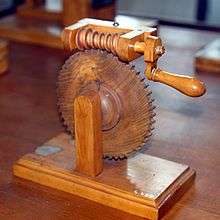
A worm drive is a gear arrangement in which a worm (which is a gear in the form of a screw) meshes with a worm gear (which is similar in appearance to a spur gear). The two elements are also called the worm screw and worm wheel. The terminology is often confused by imprecise use of the term worm gear to refer to the worm, the worm gear, or the worm drive as a unit.
Like other gear arrangements, a worm drive can reduce rotational speed or transmit higher torque. A worm is an example of a screw, one of the six simple machines.
Explanation
A gearbox designed using a worm and worm-wheel is considerably smaller than one made from plain spur gears, and has its drive axes at 90° to each other. With a single start worm, for each 360° turn of the worm, the worm-gear advances only one tooth of the gear. Therefore, regardless of the worm's size (sensible engineering limits notwithstanding), the gear ratio is the "size of the worm gear - to - 1". Given a single start worm, a 20 tooth worm gear reduces the speed by the ratio of 20:1. With spur gears, a gear of 12 teeth must match with a 240 tooth gear to achieve the same 20:1 ratio. Therefore, if the diametrical pitch (DP) of each gear is the same, then, in terms of the physical size of the 240 tooth gear to that of the 20 tooth gear, the worm arrangement is considerably smaller in volume.
Types
There are three different types of gears that can be used in a worm drive.
The first are non-throated worm gears. These don't have a throat, or groove, machined around the circumference of either the worm or worm wheel. The second are single-throated worm gears, in which the worm wheel is throated. The final type are double-throated worm gears, which have both gears throated. This type of gearing can support the highest loading.[1]
An enveloping (hourglass) worm has one or more teeth and increases in diameter from its middle portion toward both ends.[2]
Double-enveloping wormgearing comprises enveloping worms mated with fully enveloping wormgears. It is also known as globoidal wormgearing.[3]
Direction of transmission
Unlike with ordinary gear trains, the direction of transmission (input shaft vs output shaft) is not reversible when using large reduction ratios, due to the greater friction involved between the worm and worm-wheel, when usually a single start (one spiral) worm is used. This can be an advantage when it is desired to eliminate any possibility of the output driving the input. If a multistart worm (multiple spirals) is used then the ratio reduces accordingly and the braking effect of a worm and worm-gear may need to be discounted, as the gear may be able to drive the worm.
Worm gear configurations in which the gear cannot drive the worm are called self-locking. Whether a worm and gear is self-locking depends on the lead angle, the pressure angle, and the coefficient of friction.
Applications

In early 20th century automobiles prior to the introduction of power steering, the effect of a flat or blowout on one of the front wheels tended to pull the steering mechanism toward the side with the flat tire. The use of a worm screw reduced this effect. Further worm drive development led to recirculating ball bearings to reduce frictional forces, which transmitted some steering force to the wheel. This aids vehicle control and reduces wear that could cause difficulties in steering precisely.
Worm drives are a compact means of substantially decreasing speed and increasing torque. Small electric motors are generally high-speed and low-torque; the addition of a worm drive increases the range of applications that it may be suitable for, especially when the worm drive's compactness is considered.
Worm drives are used in presses, rolling mills, conveying engineering, mining industry machines, on rudders, and worm drive saws. In addition, milling heads and rotary tables are positioned using high-precision duplex worm drives with adjustable backlash. Worm gears are used on many lift/elevator and escalator-drive applications due to their compact size and the non-reversibility of the gear.
In the era of sailing ships, the introduction of a worm drive to control the rudder was a significant advance. Prior to its introduction, a rope drum drive controlled the rudder. Rough seas could apply substantial force to the rudder, often requiring several men to steer the vessel—some drives had two large-diameter wheels so up to four crewmen could operate the rudder.
.jpg)
Worm drives have been used in a few automotive rear-axle final drives (though not the differential itself). They took advantage of the location of the gear being at either the very top or very bottom of the differential crown wheel. In the 1910s they were common on trucks; to gain the most clearance on muddy roads the worm gear was placed on top. In the 1920s the Stutz firm used them on its cars; to have a lower floor than its competitors, the gear was located on the bottom. An example from around 1960 was the Peugeot 404. The worm gear carries the differential gearing, which protects the vehicle against rollback. This ability has largely fallen from favour due to the higher-than-necessary reduction ratios.
A more recent exception to this is the Torsen differential, which uses worms and planetary worm gears in place of the bevel gearing of conventional open differentials. Torsen differentials are most prominently featured in the HMMWV and some commercial Hummer vehicles, and as a centre differential in some all wheel drive systems, such as Audi's quattro. Very heavy trucks, such as those used to carry aggregates, often use a worm gear differential for strength. The worm drive is not as efficient as a hypoid gear, and such trucks invariably have a very large differential housing, with a correspondingly large volume of gear oil, to absorb and dissipate the heat created.
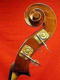
Worm drives are used as the tuning mechanism for many musical instruments, including guitars, double-basses, mandolins, bouzoukis, and many banjos (although most high-end banjos use planetary gears or friction pegs). A worm drive tuning device is called a machine head.
Plastic worm drives are often used on small battery-operated electric motors, to provide an output with a lower angular velocity (fewer revolutions per minute) than that of the motor, which operates best at a fairly high speed. This motor-worm-gear drive system is often used in toys and other small electrical devices.
A worm drive is used on jubilee-type hose clamps or jubilee clamps. The tightening screw's worm thread engages with the slots on the clamp band.
Occasionally a worm gear is designed to run in reverse, resulting in the output shaft turning much faster than the input. Examples of this may be seen in some hand-cranked centrifuges or the wind governor in a musical box.
Left hand and right hand worm
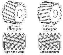
A right hand helical gear or right hand worm is one in which the teeth twist clockwise as they recede from an observer looking along the axis. The designations, right hand and left hand, are the same as in the long established practice for screw threads, both external and internal. Two external helical gears operating on parallel axes must be of opposite hand. An internal helical gear and its pinion must be of the same hand.
A left hand helical gear or left hand worm is one in which the teeth twist anticlockwise as they recede from an observer looking along the axis.[4]
Manufacture
Worm wheels are first gashed to rough out the teeth and then hobbed to the final dimensions.[5]
See also
References
- ↑ "Worm Gears". Retrieved 2009-05-01.
- ↑ Gear Nomenclature, Definition of Terms with Symbols. American Gear Manufacturers Association. p. 3. ISBN 1-55589-846-7. OCLC 65562739. ANSI/AGMA 1012-G05.
- ↑ Gear Nomenclature, Definition of Terms with Symbols. American Gear Manufacturers Association. p. 4. ISBN 1-55589-846-7. OCLC 65562739. ANSI/AGMA 1012-G05.
- ↑ Gear Nomenclature, Definition of Terms with Symbols. American Gear Manufacturers Association. p. 72. ISBN 1-55589-846-7. OCLC 65562739. ANSI/AGMA 1012-G05.
- ↑ Oberg 1920, pp. 213–214.
Bibliography
- Oberg, Erik (1920). "Spiral and worm gearing". The Industrial Press.
External links
| Wikimedia Commons has media related to Worm gears. |
- Kinematic Models for Design Digital Library (KMODDL)
Movies and photos of hundreds of working mechanical-systems models at Cornell University. Also includes an e-book library of classic texts on mechanical design and engineering. - Formulae & Calculations for Worm Drive
- Various Metric Gears downloadable design specifications, 2D-3D models and catalogues
- Various Worm Gearboxes, 3D models
- Machining of Worm Shaft and Worm Gears