XLR connector

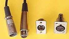
The XLR connector is a style of electrical connector, primarily found on professional audio, video, and stage lighting equipment. The connectors are circular in design and have between 3 and 7 pins. They are most commonly associated with balanced audio interconnection, including AES3 digital audio, but are also used for lighting control, low-voltage power supplies, and other applications. XLR connectors are available from a number of manufacturers and are covered by an international standard for dimensions, IEC 61076-2-103.[1] They are superficially similar to the older and smaller DIN connector range, but are not physically compatible with them.
A smaller version, the Mini XLR Connector, is used on smaller equipment.
History and manufacturers

The XLR connector was invented by James H. Cannon, founder of Cannon Electric in Los Angeles, California (now part of ITT Corporation), and for this reason it was sometimes colloquially known as a Cannon plug or Cannon connector and in Japan as Cannon jack, though this term has since fallen out of common usage in the industry. Originally manufactured as the Cannon X series, by 1950 a locking mechanism was added (Cannon XL)[2] and by 1955[2] a version surrounding the female contacts with a synthetic rubber polychloroprene insulation using the part number prefix XLR.[3][4] There was also an XLP series which used a hard plastic insulation, but was otherwise the same.[2] ITT Cannon originally manufactured XLR connectors in two locations Kanagawa, Japan and Melbourne, Australia. The Australian operation was sold to Alcatel Components in 1992 and then acquired by Amphenol in 1998. ITT Cannon continues to manufacture XLR connectors in Japan.
The Switchcraft corporation later started manufacturing compatible connectors, followed by Neutrik. Neutrik made a number of improvements to the connector and its second-generation design (known as the X-series) had just four parts for the cable connector and eliminated the small screws used by both Cannon and Switchcraft, which were prone to working loose, falling out and becoming lost. These improvements have made Neutrik the most popular brand of XLR connector.
Unbranded XLRs are also made by East Asian manufacturers. Originally these were copies of the Cannon or Switchcraft designs, but in recent years the Neutrik designs have also been copied in large numbers.
Design
XLR connectors are available in male and female versions in both cable and chassis mounting designs, a total of four styles. This is slightly unusual as many other connector designs omit one of the styles (typically a chassis mounting male connector).
The female XLR connectors are designed to first connect pin 1 (the earth pin), before the other pins make contact, when a male XLR connector is inserted. With the ground connection established before the signal lines are connected, the insertion (and removal) of XLR connectors in live equipment is possible without picking up external signals (as usually happens with, for example, RCA connectors).
The number of pins varies. As of 2016, XLR connectors are available with up to 10 pins,[5] and mini XLR connectors with up to eight. XLR connectors from different manufacturers will intermate, with the exception of Switchcraft six-pin models, which use a non-standard arrangement for the pins.
Current patterns and applications
Three-pin (XLR3)
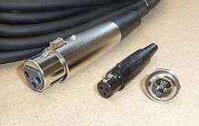
Three-pin XLR connectors are by far the most common style, and are an industry standard for balanced audio signals. The great majority of professional microphones use the XLR connector. In previous years, they were used for loudspeaker connections, for instance by Trace Elliot in its bass enclosures.[6] The XLR could accept 14 AWG (1.6 mm) wire with a current-carrying capacity of 15 amps, suitable for most loudspeakers, but they have been superseded by the Speakon connector for professional loudspeakers. The Speakon connector accepts larger wire and carries more current, and it provides a better shield for the contacts, which may carry dangerous voltages when connected to an amplifier.[7]
Three-pin XLR connectors are used to interconnect powered speakers with line-level signals. This use is commonly seen in PA system applications and seems to be growing more common.
Rechargeable devices exist that use three-pin XLR connectors. These can be found on electric powered mobility wheelchairs and scooters. The connectors carry from 2 to 10 amps at 24 volts.
An obsolete use for three-pin XLR connectors was for MIDI data on some Octave-Plateau synthesizers including the Voyetra-8.
The three-pin XLR connector is commonly used for DMX512, on lighting and related control equipment.,[8] particularly at the budget / DJ end of the market. However, using three-pin XLR connectors for DMX512 is specifically prohibited by section 7.1.2 of the DMX512 standard.[9] Use of the three-pin XLR in this context firstly presents a risk of damage to the lighting equipment should an audio cable carrying 48 volt phantom power be accidentally connected, and secondly encourages the use of cable following analogue audio specifications for DMX, which can lead to signal degradation and unreliable operation of the DMX network.
Four-pin (XLR4)
Four-pin XLR connectors are used in a variety of applications.[10]
They are the standard connector for intercom headsets, such as systems made by ClearCom and Telex. Two pins are used for the mono headphone signal and two pins for the unbalanced microphone signal.
Another common use is for DC power connections for professional film and video cameras and related equipment. Some desk microphones with LEDs use them. The fourth pin is used to power the LED indicating that the microphone is on. [11] Other uses for the four-pin XLR include some scrollers (colour changing devices for stage lighting), AMX analog lighting control (now obsolete) and some pyrotechnic equipment.
Five-pin (XLR5)
Five-pin XLR connectors are the standard for DMX512 digital lighting control.[12]
Other common uses are for dual-element or stereo microphones (two balanced audio signals with a common ground) and stereo intercom headset (3 pins for the stereo headphone signal - left, right, and ground, and 2 pins for the unbalanced microphone signal).
Additionally, Five-Pin XLR is commonly used for DC power in audio equipment.
Six-pin (XLR6)
Six-pin XLR connectors are used for dual channel intercom systems[13] and stage lighting control applications.[14][15][16] Another common use is professional stereo headset with balanced microphone (headphone left-pin 4, headphone right-pin 5, headphone common-pin 3, mic high-pin 1, mic low-pin 2, mic ground-pin 6).
Seven-pin (XLR7)
Seven-pin XLR connectors are used to connect some valve (tube) condenser microphones to their power supplies (carrying signal, polarisation voltage, heater and HT).[17]
Used by several models of Le Maitre and Ultratec fog machines for remote control.
An obsolete use for seven-pin XLR connectors was analogue lighting control signals, as well as for wired intercom in broadcast studios, specifically with Ward-Beck intercoms.
PDN
The loudspeaker Cannon (known as a PDN connector) had blue or white insulation (depending on its gender), was intended for connections between audio power amplifiers and loudspeakers. These are manufactured by Amphenol (formerly by Alcatel Components and ITT Cannon Australia).
Obsolete patterns

Many other types of connectors using the XLR type shell exist, with various pin configurations. Most notable are two now obsolete three-pin patterns manufactured by ITT Cannon.
The power Cannon (also called the XLR-LNE connector) had shrouded pins and red insulation, it was intended as a mains power plug, but has been superseded by the IEC 60320 series of connectors and increasingly, more recently, the PowerCon connector developed by Neutrik.
Two-pin
Two-pin XLR connectors were used in the 12V DC power supply connection of Yamaha CP-series Electric Grand pianos.
Technical usage information
This section contains more technical information relating the most common applications of XLR connectors.
Three-pin in audio use
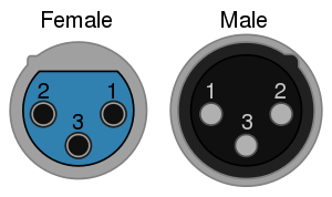
EIA Standard RS-297-A describes the use of the three-pin XLR - known as XLR3 - for balanced audio signal level applications:
 | |
| Pin | Function |
|---|---|
| 1 | Chassis ground (cable shield) |
| 2 | Positive polarity terminal for balanced audio circuits (aka "hot") |
| 3 | Negative polarity terminal for balanced circuits (aka "cold")[18] |
Prior to the introduction of this standard, the wiring of pins 2 and 3 varied. The pin 2 "hot" and pin 3 "cold" convention was typically used by European and Japanese equipment manufacturers, but American companies used pin 3 "hot" and pin 2 "cold". This caused problems when interconnecting equipment with unbalanced connections. The pin 3 "hot" convention is now obsolete but is still found on vintage equipment.[19] Pin 1 has always been ground and/or shield if the cable is shielded, and many connectors connect it internally to the connector shell or case.
Although covered in industry technical standards,[20][21] there is still some disagreement on the best way to handle the use of pin 1 for grounding (earthing). The main controversy is whether the shell of the connector should be connected to pin 1 or the shield, or left floating. AES standards mentioned above recommend that shells of cable-mounted connectors should never be connected to pin 1 or the shield, because inadvertent contact of the shell with another grounded surface while in use can create unwanted current paths for fault current, potentially causing hum and other noise. On the other hand, equipment containing active circuitry should always have pin 1 connected to the conductive enclosure of the equipment as close as possible to the point where the signal enters the enclosure. The argument centers on the radio frequency shielding provided by the shell of the connector, which may be reduced if it is left floating. An alternative solution is to connect the shell to pin 1 and the shield through a small value capacitor, providing RF shielding but allowing very little audio-frequency current to flow. This capability can be built into a fixed jack or a cable terminated with XLR connectors.
The standard signal flow for audio in XLR connectors is that the output is a male connector and the input is female. In other words, the pins on the plug point in the direction of signal flow. This is the opposite of power connector standards which normally use female connectors for outputs, a convention influenced by the need to prevent accidental contact with dangerous voltages. However, the voltages of microphone and line level audio signals are not hazardous. The male XLR is usually incorporated in the body of a microphone.
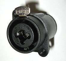
Since equipment often requires an input on a TRS phone jack or an XLR connector, Neutrik and Amphenol offer several models of combination connector that accept both XLR and 0.25 inch TS or TRS phone plugs.
Three-pin - power
The three-pin XLR is used as a low voltage power connector.
| Use | pin 1 | pin 2 | pin 3 | note |
|---|---|---|---|---|
| console light <1990 | chassis shield | 12 Vac black | 0 Vac white | White connected to center tap of extreme low voltage transformer. |
| console light >2000[22] | chassis shield | 12 Vdc red | 0 Vdc black | 0 Vdc shunted to chassis at rectifier. |
| camera Arri | 0 Vdc | 24 Vdc | n.c. | |
| camera Panavision | 24 Vdc | 0 Vdc | n.c. | |
| charger | 28 Vdc red | 0 Vdc black | =2 | Pin 3 signals motor off. Male connector at charger. |
Four-pin - DC power
The most common standard is for pin 1 to be ground and pin 4 to be 12 volts (nominal), with pins 2 and 3 unused. This configuration is used on most professional video cameras and is also common on audio equipment designed for location use.[10] There are other non-standard arrangements, particularly found on older equipment.
Four-pin - intercom headset
Clear-Com, Telex, RTS and many other production intercom systems use four-pin XLR connectors for attaching monaural intercom headsets or handsets. The standard pinout for four-pin XLR headsets is: Pin 1 = Microphone ground (screen/shield); Pin 2 = Microphone signal ("hot") input; Pin 3 = Headphone ground (return); Pin 4 = Headphone signal ("hot") output.[23]
Five-pin - DMX512 and DC Power for Audio Systems
The five-pin XLR is the standard connector for DMX512, the most common protocol for controlling professional lighting and related equipment.[8] Three-pin XLR connectors are increasingly common instead. These are electrically compatible with a simple jumpering 1–1, 2–2, 3–3 between them. However, using three-pin XLR connectiors for DMX512 is specifically prohibited by section 7.1.2 of the DMX512 standard.[9]
Five-Pin XLR is also a common power connector in modular professional audio systems, such as the Automated Processes, Inc.'s (API) Lunchbox format.[24] This format is becoming increasingly popular and Five-Pin XLR for DC power is used by many 3rd party module and chassis developers such as BAE Audio[25] and JLM Audio.[26] It is also used by Slate Digital for the VMS1 microphone preamp.[27] Typically the pin configuration is:
Pin 1: Chassis Ground
Pin 2: Power Ground
Pin 3: Positive Voltage (Typically +15 volts or +16 volts)
Pin 4: Negative Voltage (Typically -15 volts or -16 volts)
Pin 5: Phantom Power Voltage (Typically +48 volts)
Where XLR connectors are used for DC power, the genders are reversed with respect to their standard use for line-level and mic-level audio. Typically, audio signals on XLR connectors "follow the pin," such that a male connector is an output and a female connector is an input. In most power applications (not just XLR connectors) the female connector is the output and the male connector is the input. This makes accidental contact with live parts less likely. In audio devices it also prevents accidental application of DC power to signal inputs.
Additional usage information
At one time three-pin XLR connectors were also used extensively on loudspeaker cables, as when first introduced they represented a new standard of ruggedness, and economic alternatives were not readily available. The convention was that a two-conductor loudspeaker cable had three-pin female connectors on both ends, to distinguish it from a three-conductor shielded signal level cable, which has a female connector at one end and a male at the other. Either pin 2 or 3 was live, depending on the manufacturer, with pin 1 always the 'earthy' return. This usage is now both obsolete and dangerous to equipment but is still sometimes encountered, especially on older equipment. For example, some loudspeakers have a built-in male connector as an input connector for speaker-level signal. This use was superseded in professional audio applications by the Neutrik Speakon connector.
 Male and female XLR4 panel connectors
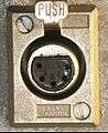 Female XLR5 panel connector
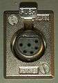 Female XLR6 panel connector
Phantom power
Some microphones such as condenser microphones require power. An alternative to battery power is phantom power, which consists of direct current applied equally through the two signal lines of a balanced audio connector, usually a three-pin XLR connector. The supply voltage is referenced to the ground pin of the connector (pin 1 of an XLR), which normally is connected to the cable shield or a ground wire in the cable or both. Phantom power is usually supplied at a nominal 48 volts DC, although lower voltages are permissible and modern microphones will often operate over a wide range.
It is common for modern mixers to have a built-in switch-operated 48-volt power supply which supplies all mic inputs with phantom power, thus eliminating the need for bulky external supplies on individual mics.
XLD keyed variant
The XLD connector is a proposed keyed variant of the XLR connector. The keys prevent accidental mixing of XLR and XLD connectors. XLD plugs and sockets are used mostly in professional audio and video electronics cabling applications.
The XLD connector is proposed by the Audio Engineering Society AES42 digital microphone interface standard.
The connectors are similar to XLR but with an extra coding key and groove that allows control over the intermating of XLD plugs and XLR sockets. A connector with the coding key installed will not mate with a connector that does not have the matching groove.[28] By suitably keying connectors, analog microphones can be protected from damage by the high current digital phantom power supply provided for digital microphones.
Mini XLR Connector
The Mini XLR Connector, also known as the "TQG" [29] or "TA3"/"TA4" [30] connector (number depending on number of poles), is used on compact items such as UHF wireless microphone beltpacks, some studio and field recording headphones, as well as Audio Technica condenser microphones, but is not in general use on major items such as mixing desks. The Mini XLR Connector was first devised by Switchcraft [31] and is also available from Rean,[32] and various other sources. As yet, the Mini XLR connectors do not appear to be covered by any ISO or national standard.
See also
References
- ↑ "IEC 61076-2-103 ed1.0. Connectors for electronic equipment - Part 2-103: Circular connectors - Detail specification for a range of multipole connectors (type 'XLR')". International Electrotechnical Commission. 3 August 2004. Retrieved 2012-03-23.
- 1 2 3 Rayburn, Ray (16 December 2008). "A brief history of the XLR connector". Sound First. Archived from the original on 22 February 2011.
- ↑ McGuire, Sam; Pritts, Roy (2013). Audio Sampling: A Practical Guide. Taylor & Francis. p. 49. ISBN 1136122621.
- ↑ Rane Professional Audio Reference description
- ↑ http://www.prosoundweb.com/mobile/article/neutrik_debuts_10-pin_xlr_connector/
- ↑ Ashton, Adrian (2006). The Bass Handbook. Hal Leonard Corporation. p. 110. ISBN 0879308729.
- ↑ Duncan, Ben (2002). The Live Sound Manual. Hal Leonard Corporation. p. 138. ISBN 0879306998.
- 1 2 "DMX512 Standard Pinouts". Retrieved 2012-03-12.
- 1 2 "American National Standard E1.11 – 2008" (PDF). PLASA Standards. Professional Lighting and Sound Association. p. 12. Retrieved 26 October 2014.
- 1 2 Professional audio / entertainment devices 4 pin XLR connector pinout diagram @ pinoutsguide.com
- ↑
- ↑ "DMX (DMX512) pinout". Retrieved 2012-03-08.
- ↑ "Clear-Com RS-602 beltpack". Retrieved 2012-03-16.
- ↑ "ETCLink Documentation". Archived from the original on 21 December 2011.
- ↑ "ETC RFU Documentation". Archived from the original on 21 December 2011.
- ↑ "ETC RFU and ETCLink Pinout". Archived from the original on 11 May 2013.
- ↑ "7-pin XLR Cable". Sterling Audio. Retrieved 2012-09-06.
- ↑ Audio Engineering Society. AES14-1992 AES Standard for professional audio equipment—Application of connectors, part 1, XLR-type polarity and gender.
- ↑ "3-Pin XLR Audio Pinout". Clark wire and cable. Retrieved 2012-03-12.
- ↑ AES48-2005
- ↑ AES54-3-xxxx,
- ↑ Yamaha EMX5016cf manual
- ↑
- ↑ http://apiaudio.com/product_specs.php?id=110
- ↑ http://www.baeaudio.com/products/500-series-racks
- ↑ http://www.jlmaudio.com/shop/16v-2a-48v-120ma-65w-smps.html
- ↑ http://download.slatedigital.com/vmr/Virtual%20Microphone%20System%20-%20User%20Guide.pdf
- ↑ Don Davis, Eugene Patronis Sound system engineering Third edition, Focal Press, 2006 ISBN 0-240-80830-4, page 448
- ↑ Switchcraft : Mini XLR Archived 6 February 2016 at the Wayback Machine.
- ↑ https://web.archive.org/web/20160206103225/http://www.shure.com/americas/products/accessories/wireless-systems/wireless-systems-cables-connectors. Archived from the original on 6 February 2016. Retrieved 6 February 2016. Missing or empty
|title=(help) - ↑ Switchcraft : Specification Archived 27 October 2014 at the Wayback Machine.
- ↑ RT3FCT-B - REAN Connectors
External links
| Wikimedia Commons has media related to XLR connectors. |