Adaptive optics


Adaptive optics (AO) is a technology used to improve the performance of optical systems by reducing the effect of wavefront distortions: it aims at correcting the deformations of an incoming wavefront by deforming a mirror in order to compensate for the distortion. It is used in astronomical telescopes[1] and laser communication systems to remove the effects of atmospheric distortion, in microscopy,[2] optical fabrication[3] and in retinal imaging systems[4] to reduce optical aberrations. Adaptive optics works by measuring the distortions in a wavefront and compensating for them with a device that corrects those errors such as a deformable mirror or a liquid crystal array.
Adaptive optics should not be confused with active optics, which works on a longer timescale to correct the primary mirror geometry.
Other methods can achieve resolving power exceeding the limit imposed by atmospheric distortion, such as speckle imaging, aperture synthesis, and lucky imaging, or by moving outside the atmosphere with space telescopes, such as the Hubble Space Telescope.
History
Adaptive optics was first envisioned by Horace W. Babcock in 1953,[6] and was also considered in science fiction, as in Poul Anderson's novel Tau Zero (1970), but it did not come into common usage until advances in computer technology during the 1990s made the technique practical.
Some of the initial development work on adaptive optics was done by the US military during the Cold War and was intended for use in tracking Soviet satellites.[7]
Microelectromechanical systems (MEMS) deformable mirrors are currently the most widely used technology in wavefront shaping applications for adaptive optics given their versatility, maturity of technology and the high resolution wavefront correction that they afford.
Tip–tilt correction
The simplest form of adaptive optics is tip-tilt correction,[8] which corresponds to correction of the tilts of the wavefront in two dimensions (equivalent to correction of the position offsets for the image). This is performed using a rapidly moving tip–tilt mirror that makes small rotations around two of its axes. A significant fraction of the aberration introduced by the atmosphere can be removed in this way.
Tip–tilt mirrors are effectively segmented mirrors having only one segment which can tip and tilt, rather than having an array of multiple segments that can tip and tilt independently. Due to the relative simplicity of such mirrors and having a large stroke, meaning they have large correcting power, most AO systems use these, first, to correct low order aberrations. Higher order aberrations may then be corrected with deformable mirrors.
In astronomy

Atmospheric seeing
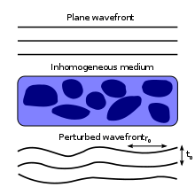

When light from a star or another astronomical object enters the Earth's atmosphere, atmospheric turbulence (introduced, for example, by different temperature layers and different wind speeds interacting) can distort and move the image in various ways[9] (see astronomical seeing for a full discussion). Visual images produced by any telescope larger than approximately 20 centimeters are blurred by these distortions.
Wavefront sensing and correction
An adaptive optics system tries to correct these distortions, using a wavefront sensor which takes some of the astronomical light, a deformable mirror that lies in the optical path, and a computer that receives input from the detector. The wavefront sensor measures the distortions the atmosphere has introduced on the timescale of a few milliseconds; the computer calculates the optimal mirror shape to correct the distortions and the surface of the deformable mirror is reshaped accordingly. For example, an 8–10 m telescope (like the VLT or Keck) can produce AO-corrected images with an angular resolution of 30–60 milliarcsecond (mas) resolution at infrared wavelengths, while the resolution without correction is of the order of 1 arcsecond.
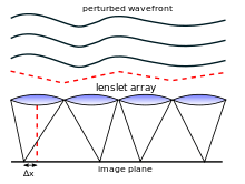
In order to perform adaptive optics correction, the shape of the incoming wavefronts must be measured as a function of position in the telescope aperture plane. Typically the circular telescope aperture is split up into an array of pixels in a wavefront sensor, either using an array of small lenslets (a Shack–Hartmann sensor), or using a curvature or pyramid sensor which operates on images of the telescope aperture. The mean wavefront perturbation in each pixel is calculated. This pixelated map of the wavefronts is fed into the deformable mirror and used to correct the wavefront errors introduced by the atmosphere. It is not necessary for the shape or size of the astronomical object to be known – even Solar System objects which are not point-like can be used in a Shack–Hartmann wavefront sensor, and time-varying structure on the surface of the Sun is commonly used for adaptive optics at solar telescopes. The deformable mirror corrects incoming light so that the images appear sharp.
Using guide stars
Natural guide stars
Because a science target is often too faint to be used as a reference star for measuring the shape of the optical wavefronts, a nearby brighter guide star can be used instead. The light from the science target has passed through approximately the same atmospheric turbulence as the reference star's light and so its image is also corrected, although generally to a lower accuracy.
The necessity of a reference star means that an adaptive optics system cannot work everywhere on the sky, but only where a guide star of sufficient luminosity (for current systems, about magnitude 12–15) can be found very near to the object of the observation. This severely limits the application of the technique for astronomical observations. Another major limitation is the small field of view over which the adaptive optics correction is good. As the angular distance from the guide star increases, the image quality degrades. A technique known as "multiconjugate adaptive optics" uses several deformable mirrors to achieve a greater field of view.
Artificial guide stars
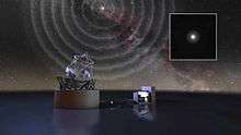
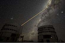
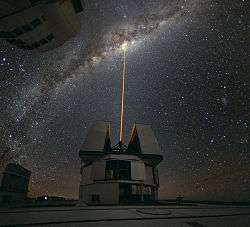
An alternative is the use of a laser beam to generate a reference light source (a laser guide star, LGS) in the atmosphere. LGSs come in two flavors: Rayleigh guide stars and sodium guide stars. Rayleigh guide stars work by propagating a laser, usually at near ultraviolet wavelengths, and detecting the backscatter from air at altitudes between 15–25 km. Sodium guide stars use laser light at 589 nm to excite sodium atoms higher in the mesosphere and thermosphere, which then appear to "glow". The LGS can then be used as a wavefront reference in the same way as a natural guide star – except that (much fainter) natural reference stars are still required for image position (tip/tilt) information. The lasers are often pulsed, with measurement of the atmosphere being limited to a window occurring a few microseconds after the pulse has been launched. This allows the system to ignore most scattered light at ground level; only light which has travelled for several microseconds high up into the atmosphere and back is actually detected.
In retinal imaging

Ocular aberrations are distortions in the wavefront passing through the pupil of the eye. These optical aberrations diminish the quality of the image formed on the retina, sometimes necessitating the wearing of spectacles or contact lenses. In the case of retinal imaging, light passing out of the eye carries similar wavefront distortions, leading to an inability to resolve the microscopic structure (cells and capillaries) of the retina. Spectacles and contact lenses correct "low-order aberrations", such as defocus and astigmatism, which tend to be stable in humans for long periods of time (months or years). While correction of these is sufficient for normal visual functioning, it is generally insufficient to achieve microscopic resolution. Additionally, "high-order aberrations", such as coma, spherical aberration, and trefoil, must also be corrected in order to achieve microscopic resolution. High-order aberrations, unlike low-order, are not stable over time, and may change over time scales of 0.1s to 0.01s. The correction of these aberrations requires continuous, high-frequency measurement and compensation.
Measurement of ocular aberrations
Ocular aberrations are generally measured using a wavefront sensor, and the most commonly used type of wavefront sensor is the Shack-Hartmann. Ocular aberrations are caused by spatial phase nonuniformities in the wavefront exiting the eye. In a Shack-Hartmann wavefront sensor, these are measured by placing a two-dimensional array of small lenses (lenslets) in a pupil plane conjugate to the eye's pupil, and a CCD chip at the back focal plane of the lenslets. The lenslets cause spots to be focused onto the CCD chip, and the positions of these spots are calculated using a centroiding algorithm. The positions of these spots are compared with the positions of reference spots, and the displacements between the two are used to determine the local curvature of the wavefront—an estimate of the phase nonuniformities causing aberration.
Correction of ocular aberrations
Once the local phase errors in the wavefront are known, they can be corrected by placing a phase modulator such as a deformable mirror at yet another plane in the system conjugate to the eye's pupil. The phase errors can be used to reconstruct the wavefront, which can then be used to control the deformable mirror. Alternatively, the local phase errors can be used directly to calculate the deformable mirror instructions.
Open loop vs. closed loop operation
If the wavefront error is measured before it has been corrected by the wavefront corrector, then operation is said to be "open loop". If the wavefront error is measured after it has been corrected by the wavefront corrector, then operation is said to be "closed loop". In the latter case then the wavefront errors measured will be small, and errors in the measurement and correction are more likely to be removed. Closed loop correction is the norm.
Applications
Adaptive optics was first applied to flood-illumination retinal imaging to produce images of single cones in the living human eye. It has also been used in conjunction with scanning laser ophthalmoscopy to produce (also in living human eyes) the first images of retinal microvasculature and associated blood flow and retinal pigment epithelium cells in addition to single cones. Combined with optical coherence tomography, adaptive optics has allowed the first three-dimensional images of living cone photoreceptors to be collected.[11]
Other uses
Besides its use for improving nighttime astronomical imaging and retinal imaging, adaptive optics technology has also been used in other settings. Adaptive optics is used for solar astronomy at observatories such as the Swedish 1-m Solar Telescope. It is also expected to play a military role by allowing ground-based and airborne laser weapons to reach and destroy targets at a distance including satellites in orbit. The Missile Defense Agency Airborne Laser program is the principal example of this.
Adaptive optics has been used to enhance the performance of free space optical communication systems[13] [14] and to control the spatial output of optical fibers.[15]
Medical applications include imaging of the retina, where it has been combined with optical coherence tomography.[16] Development of an Adaptive Scanning Optical Microscope (ASOM) was announced by Thorlabs in April 2007. Adaptive and active optics are also being developed for use in glasses to achieve better than 20/20 vision, initially for military applications.[17]
After propagation of a wavefront, parts of it may overlap leading to interference and preventing adaptive optics from correcting it. Propagation of a curved wavefront always leads to amplitude variation. This needs to be considered if a good beam profile is to be achieved in laser applications.
Adaptive optics, especially wavefront-coding spatial light modulators, are frequently used in optical trapping applications to multiplex and dynamically reconfigure laser foci that are used to micro-manipulate biological specimens.
Beam stabilization
A rather simple example is the stabilization of the position and direction of laser beam between modules in a large free space optical communication system. Fourier optics is used to control both direction and position. The actual beam is measured by photo diodes. This signal is fed into some Analog-to-digital converters and a microcontroller runs a PID controller algorithm. The controller drives some digital-to-analog converters which drive stepper motors attached to mirror mounts.
If the beam is to be centered onto 4-quadrant diodes, no Analog-to-digital converter is needed. Operational amplifiers are sufficient.
See also
- Active optics
- Adjustable-focus eyeglasses
- Angular diameter
- Angular size
- Atmospheric correction (for satellite imaging of the earth)
- Claire Max, adaptive optics pioneer
- Deformable mirror
- Greenwood frequency
- Holography: real-time holography
- Image stabilization
- List of telescope parts and construction
- Nonlinear optics: optical phase conjugation
- Wavefront
- Wavefront sensor
- William Happer, adaptive optics pioneer
References
- ↑ Beckers, J.M. (1993). "Adaptive Optics for Astronomy: Principles, Performance, and Applications". Annual Review of Astronomy and Astrophysics. 31 (1): 13–62. Bibcode:1993ARA&A..31...13B. doi:10.1146/annurev.aa.31.090193.000305.
- ↑ Booth, Martin J (15 December 2007). "Adaptive optics in microscopy" (PDF). Philosophical Transactions of the Royal Society A: Mathematical, Physical and Engineering Sciences. 365 (1861): 2829–2843. Bibcode:2007RSPTA.365.2829B. doi:10.1098/rsta.2007.0013. Retrieved 30 November 2012.
- ↑ Booth, Martin J.; Schwertner, Michael; Wilson, Tony; Nakano, Masaharu; Kawata, Yoshimasa; Nakabayashi, Masahito; Miyata, Sou (1 January 2006). "Predictive aberration correction for multilayer optical data storage" (PDF). Applied Physics Letters. 88 (3): 031109. Bibcode:2006ApPhL..88c1109B. doi:10.1063/1.2166684. Retrieved 30 November 2012.
- ↑ Roorda, A; Williams, DR (2001). "Retinal imaging using adaptive optics". In MacRae, S; Krueger, R; Applegate, RA. Customized Corneal Ablation: The Quest for SuperVision. SLACK, Inc. pp. 11–32. ISBN 1-55642-625-9.
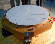
- ↑ "Improved Adaptive Optics Mirror Delivered". ESO Announcement. Retrieved 6 February 2014.
- ↑ "'Adaptive optics' come into focus". BBC. 18 February 2011. Retrieved 24 June 2013.
- ↑ Joe Palca (24 June 2013). "For Sharpest Views, Scope The Sky With Quick-Change Mirrors". NPR. Retrieved 24 June 2013.
- ↑ Watson, Jim. Tip-Tilt Correction for Astronomical Telescopes using Adaptive Control (PDF). Wescon – Integrated Circuit Expo 1997.
- ↑ Max, Claire. Introduction to Adaptive Optics and its History (PDF). American Astronomical Society 197th Meeting.
- ↑ "Austrian Superfast Adaptive Optics Algorithms for the E-ELT". ESO. Retrieved 12 March 2014.
- ↑ "High-speed volumetric imaging of cone photoreceptors with adaptive optics spectral-domain optical coherence tomography". Optics Express. Retrieved 27 Sep 2012.
- ↑ "GRAAL on a Quest to Improve HAWK-I's Vision". ESO Picture of the Week. Retrieved 18 November 2011.
- ↑ "AOptix Technologies Introduces AO-Based FSO Communications Product". adaptiveoptics.org. June 2005. Retrieved 28 June 2010.
- ↑ "Demonstration of free-space optical communication link incorporating a closed-loop tracking system for mobile platforms". SPIE Proceedings. 2004.
- ↑ Kreysing, M.; Ott, D.; Schmidberger, M. J.; Otto, O.; Schürmann, M.; Martín-Badosa, E.; Whyte, G.; Guck, J. (2014). "Dynamic operation of optical fibres beyond the single-mode regime facilitates the orientation of biological cells". Nature Communications. 5: 5481. Bibcode:2014NatCo...5E5481K. doi:10.1038/ncomms6481.
- ↑ "Retinal OCT Imaging System to Incorporate Adaptive Optics". adaptiveoptics.org. 10 April 2006. Retrieved 28 June 2010.
- ↑ "PixelOptics to Develop SuperVision for U.S. Military; $3.5 Million in Funding Provided ASDNews". ASDNews. Retrieved 28 June 2010.
Further reading
- Duffner, Robert W., and Robert Q. Fugate. The Adaptive Optics Revolution: A History (University of New Mexico Press, 2009) 485pp
- Thomas H. Rimmele; Jose Marino (2011). "Solar Adaptive Optics". Living Rev. Sol. Phys. 8 (2). Bibcode:2011LRSP....8....2R. doi:10.12942/lrsp-2011-2. Retrieved 12 June 2011.
- Tyson, Robert (2010). Principles of Adaptive Optics (Third ed.). Taylor & Francis. Bibcode:1991pao..book.....T. ISBN 978-1-4398-0858-0.
- Roddier, François (November 2004). François Roddier, ed. Adaptive Optics in Astronomy. Cambridge, UK: Cambridge University Press. p. 419. Bibcode:2004aoa..book.....R. ISBN 0-521-61214-4.
External links
| Wikimedia Commons has media related to Adaptive optics. |
- 10th International Workshop on Adaptive Optics for Industry and Medicine, Padova (Italy), 15-19 June 2015
- Adaptive Optics Tutorial at CTIO A. Tokovinin
- Research groups and companies with interests in Adaptive Optics
- Space-based vs. Ground-based telescopes with Adaptive Optics
- Ten Years of VLT Adaptive Optics (ESO : ann11078 : 25 November 2011)
- Center for Adaptive Optics