Analog television
Analog television or analogue television is the original television technology that uses analog signals to transmit video and audio.[1] In an analog television broadcast, the brightness, colors and sound are represented by rapid variations of either the amplitude, frequency or phase of the signal.
Analog signals vary over a continuous range of possible values which means that electronic noise and interference becomes reproduced by the receiver. So with analog, a moderately weak signal becomes snowy and subject to interference. In contrast, a moderately weak digital signal and a very strong digital signal transmit equal picture quality. Analog television may be wireless or can be distributed over a cable network using cable converters.
All broadcast television systems preceding digital transmission of digital television (DTV) used analog signals.
Analog television around the world has been in the process of shutting down since the late 2000s.
Development
The earliest systems were mechanical television systems which used spinning disks with patterns of holes punched into the disc to scan an image. A similar disk reconstructed the image at the receiver. Synchronization of the receiver disc rotation was handled through sync pulses broadcast with the image information. However these mechanical systems were slow, the images were dim and flickered severely, and the image resolution very low. Camera systems used similar spinning discs and required intensely bright illumination of the subject for the light detector to work.
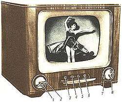
Analog television did not really begin as an industry until the development of the cathode-ray tube (CRT), which uses a focused electron beam to trace lines across a phosphor coated surface. The electron beam could be swept across the screen much faster than any mechanical disc system, allowing for more closely spaced scan lines and much higher image resolution. Also far less maintenance was required of an all-electronic system compared to a spinning disc system. All-electronic systems became popular with households after the Second World War.
Standards
Broadcasters using analog television systems encode their signal using different systems. The official systems of transmission are named : A, B, C, D, E, F, G, H, I, K, K1, L, M and N. These systems determine the Number of lines, Channel width, Vision bandwidth, vision/sound separation, etc.
The colours on those systems are encoded with one of the three colour coding NTSC, PAL or SECAM,[2] and then use RF modulation to modulate this signal onto a Very high frequency (VHF) or Ultra high frequency (UHF) carrier. Each frame of a television image is composed of lines drawn on the screen. The lines are of varying brightness; the whole set of lines is drawn quickly enough that the human eye perceives it as one image. The next sequential frame is displayed, allowing the depiction of motion. The analog television signal contains timing and synchronization information, so that the receiver can reconstruct a two-dimensional moving image from a one-dimensional time-varying signal.
The first commercial television systems were black-and-white; the beginning of color television was in the 1950s.[3]
A practical television system needs to take luminance, chrominance (in a color system), synchronization (horizontal and vertical), and audio signals, and broadcast them over a radio transmission. The transmission system must include a means of television channel selection.
Analog broadcast television systems come in a variety of frame rates and resolutions. Further differences exist in the frequency and modulation of the audio carrier. The monochrome combinations still existing in the 1950s are standardized by the International Telecommunication Union (ITU) as capital letters A through N. When color television was introduced, the hue and saturation information was added to the monochrome signals in a way that black & white televisions ignore. In this way backwards compatibility was achieved. That concept is true for all analog television standards.
There were three standards for the way the additional color information can be encoded and transmitted. The first was the American NTSC (National Television Systems Committee) color television system. The European/Australian PAL (Phase Alternation Line rate) and the French-former Soviet Union SECAM (Séquentiel Couleur Avec Mémoire) standard were developed later and attempt to cure certain defects of the NTSC system. PAL's color encoding is similar to the NTSC systems. SECAM, though, uses a different modulation approach than PAL or NTSC.
In principle, all three color encoding systems can be combined with any scan line/frame rate combination. Therefore, in order to describe a given signal completely, it's necessary to quote the color system and the broadcast standard as a capital letter. For example, United States, Canada, Mexico and South Korea uses NTSC-M (Many of these transitioned or transitioning to digital), Japan uses NTSC-J (Discontinued in 2012, when Japan transitioned to digital (ISDB)), the UK uses PAL-I (Discontinued in 2012, when UK transitioned to digital (DVB-T)), France uses SECAM-L (Discontinued in 2011, when France transitioned to digital (DVB-T)), much of Western Europe and Australia uses PAL-B/G (Many of these transitioned or transitioning to DVB-T as digital television standards), most of Eastern Europe uses SECAM-D/K or PAL-D/K and so on.
However, not all of these possible combinations actually exist. NTSC is currently only used with system M, even though there were experiments with NTSC-A (405 line) in the UK and NTSC-N (625 line) in part of South America. PAL is used with a variety of 625-line standards (B,G,D,K,I,N) but also with the North American 525-line standard, accordingly named PAL-M. Likewise, SECAM is used with a variety of 625-line standards.
For this reason many people refer to any 625/25 type signal as "PAL" and to any 525/30 signal as "NTSC", even when referring to digital signals; for example, on DVD-Video, which does not contain any analog color encoding, and thus no PAL or NTSC signals at all. Even though this usage is common, it is misleading, as that is not the original meaning of the terms PAL/SECAM/NTSC.
Although a number of different broadcast television systems were in use worldwide, the same principles of operation apply.[4]
In many countries, over-the-air broadcast television of analog audio and analog video signals has been discontinued, to allow the re-use of the television broadcast radio spectrum for other services such as datacasting and subchannels.
Displaying an image
A cathode-ray tube (CRT) television displays an image by scanning a beam of electrons across the screen in a pattern of horizontal lines known as a raster. At the end of each line the beam returns to the start of the next line; the end of the last line is a link that returns to the top of the screen. As it passes each point the intensity of the beam is varied, varying the luminance of that point. A color television system is identical except that an additional signal known as chrominance controls the color of the spot.
Raster scanning is shown in a slightly simplified form below.
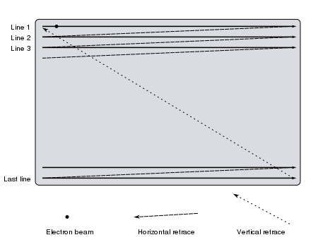
When analog television was developed, no affordable technology for storing any video signals existed; the luminance signal has to be generated and transmitted at the same time at which it is displayed on the CRT. It is therefore essential to keep the raster scanning in the camera (or other device for producing the signal) in exact synchronization with the scanning in the television.
The physics of the CRT require that a finite time interval be allowed for the spot to move back to the start of the next line (horizontal retrace) or the start of the screen (vertical retrace). The timing of the luminance signal must allow for this.

The human eye has a characteristic called Phi phenomenon. Quickly displaying successive scan images will allow the apparent illusion of smooth motion. Flickering of the image can be partially solved using a long persistence phosphor coating on the CRT, so that successive images fade slowly. However, slow phosphor has the negative side-effect of causing image smearing and blurring when there is a large amount of rapid on-screen motion occurring.
The maximum frame rate depends on the bandwidth of the electronics and the transmission system, and the number of horizontal scan lines in the image. A frame rate of 25 or 30 hertz is a satisfactory compromise, while the process of interlacing two video fields of the picture per frame is used to build the image. This process doubles the apparent number of video frames per second and further reduces flicker and other defects in transmission.
Other types of display screens
Plasma screens and LCD screens have been used in analog television sets. These types of display screens use lower voltages than older CRT displays. Many dual system television receivers, equipped to receive both analog transmissions and digital transmissions have analog tuner receiving capability and must use a television antenna.
Receiving signals
The television system for each country will specify a number of television channels within the UHF or VHF frequency ranges. A channel actually consists of two signals: the picture information is transmitted using amplitude modulation on one frequency, and the sound is transmitted with frequency modulation at a frequency at a fixed offset (typically 4.5 to 6 MHz) from the picture signal.
The channel frequencies chosen represent a compromise between allowing enough bandwidth for video (and hence satisfactory picture resolution), and allowing enough channels to be packed into the available frequency band. In practice a technique called vestigial sideband is used to reduce the channel spacing, which would be nearly twice the video bandwidth if pure AM was used.
Signal reception is invariably done via a superheterodyne receiver: the first stage is a tuner which selects a television channel and frequency-shifts it to a fixed intermediate frequency (IF). The signal amplifier performs amplification to the IF stages from the microvolt range to fractions of a volt.
Extracting the sound
At this point the IF signal consists of a video carrier signal at one frequency and the sound carrier at a fixed offset. A demodulator recovers the video signal. Also at the output of the same demodulator is a new frequency modulated sound carrier at the offset frequency. In some sets made before 1948, this was filtered out, and the sound IF of about 22 MHz was sent to an FM demodulator to recover the basic sound signal. In newer sets, this new carrier at the offset frequency was allowed to remain as intercarrier sound, and it was sent to an FM demodulator to recover the basic sound signal. One particular advantage of intercarrier sound is that when the front panel fine tuning knob is adjusted, the sound carrier frequency does not change with the tuning, but stays at the above-mentioned offset frequency. Consequently, it is easier to tune the picture without losing the sound.
So the FM sound carrier is then demodulated, amplified, and used to drive a loudspeaker. Until the advent of the NICAM and MTS systems, television sound transmissions were invariably monophonic.
Structure of a video signal
The video carrier is demodulated to give a composite video signal; this contains luminance, chrominance and synchronization signals;[5] this is identical to the video signal format used by analog video devices such as VCRs or CCTV cameras. Note that the RF signal modulation is inverted compared to the conventional AM: the minimum video signal level corresponds to maximum carrier amplitude, and vice versa. To ensure good linearity (fidelity), consistent with affordable manufacturing costs of transmitters and receivers, the video carrier is never shut off altogether. When intercarrier sound was invented later in 1948, not completely shutting off the carrier had the side effect of allowing intercarrier sound to be economically implemented.
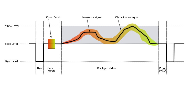
Each line of the displayed image is transmitted using a signal as shown above. The same basic format (with minor differences mainly related to timing and the encoding of color) is used for PAL, NTSC and SECAM television systems. A monochrome signal is identical to a color one, with the exception that the elements shown in color in the diagram (the color burst, and the chrominance signal) are not present.

The front porch is a brief (about 1.5 microsecond) period inserted between the end of each transmitted line of picture and the leading edge of the next line sync pulse. Its purpose was to allow voltage levels to stabilise in older televisions, preventing interference between picture lines. The front porch is the first component of the horizontal blanking interval which also contains the horizontal sync pulse and the back porch.[6][7]
The back porch is the portion of each scan line between the end (rising edge) of the horizontal sync pulse and the start of active video. It is used to restore the black level (300 mV) reference in analog video. In signal processing terms, it compensates for the fall time and settling time following the sync pulse.[6][7]
In color television systems such as PAL and NTSC, this period also includes the colorburst signal. In the SECAM system it contains the reference subcarrier for each consecutive color difference signal in order to set the zero-color reference.
In some professional systems, particularly satellite links between locations, the audio is embedded within the back porch of the video signal, to save the cost of renting a second channel.
Monochrome video signal extraction
The luminance component of a composite video signal varies between 0 V and approximately 0.7 V above the "black" level. In the NTSC system, there is a blanking signal level used during the front porch and back porch, and a black signal level 75 mV above it; in PAL and SECAM these are identical.
In a monochrome receiver the luminance signal is amplified to drive the control grid in the electron gun of the CRT. This changes the intensity of the electron beam and therefore the brightness of the spot being scanned. Brightness and contrast controls determine the DC shift and amplification, respectively.
Color video signal extraction

A color signal conveys picture information for each of the red, green, and blue components of an image (see the article on color space for more information). However, these are not simply transmitted as three separate signals, because: such a signal would not be compatible with monochrome receivers (an important consideration when color broadcasting was first introduced). It would also occupy three times the bandwidth of existing television, requiring a decrease in the number of television channels available. Furthermore, typical problems with signal transmission (such as differing received signal levels between different colors) would produce unpleasant side effects.
Instead, the RGB signals are converted into YUV form, where the Y signal represents the lightness and darkness (luminance) of the colors in the image. Because the rendering of colors in this way is the goal of both black and white (monochrome) film and black and white (monochrome) television systems, the Y signal is ideal for transmission as the luminance signal. This ensures a monochrome receiver will display a correct picture in black and white, where a given color is reproduced by a shade of gray that correctly reflects how light or dark the original color is.
The U and V signals are "color difference" signals. The U signal is the difference between the B signal and the Y signal, also known as B minus Y (B-Y), and the V signal is the difference between the R signal and the Y signal, also known as R minus Y (R-Y). The U signal then represents how "purplish-blue" or its complementary color "yellowish-green" the color is, and the V signal how "purplish-red" or its complementary "greenish-cyan" it is. The advantage of this scheme is that the U and V signals are zero when the picture has no color content. Since the human eye is more sensitive to errors in luminance than in color, the U and V signals can be transmitted in a relatively lossy (specifically: bandwidth-limited) way with acceptable results.
In the receiver, a single demodulator can extract an additive combination of U plus V. An example is the X demodulator used in the X/Z demodulation system. In that same system, a second demodulator, the Z demodulator, also extracts an additive combination of U plus V, but in a different ratio. The X and Z color difference signals are further matrixed into three color difference signals, (R-Y), (B-Y), and (G-Y). The combinations of usually two, but sometimes three demodulators were:
a) (I) / (Q), (as used in the 1954 RCA CTC-2 and the 1985 RCA "Colortrack" series, and the 1954 Arvin, and some professional color monitors in the 1990s),
b) (R-Y) / (Q), as used in the 1955 RCA 21 inch color receiver,
c) (R-Y) / (B-Y), used in the first color receiver on the market (Westinghouse, not RCA),
d) (R-Y) / (G-Y), (as used in the RCA Victor CTC-4 chassis),
e) (R-Y) / (B-Y) / (G-Y),
f) (X) / (Z), as used in many receivers of the late 50's and throughout the 60's.
In the end, further matrixing of the above color-difference signals c through f yielded the three color-difference signals, (R-Y), (B-Y), and (G-Y).
The R,G,B signals in the receiver needed for the display device (CRT, Plasma display or LCD display) are electronically derived by matrixing as follows: R is the additive combination of (R-Y) with Y, G is the additive combination of (G-Y) with Y, and B is the additive combination of (B-Y) with Y. All of this is accomplished electronically. It can be seen that in the combining process, the low resolution portion of the Y signals cancel out, leaving R,G, and B signals able to render a low-resolution image in full color. However, the higher resolution portions of the Y signals do not cancel out, and so are equally present in R, G, and B, producing the higher definition (higher resolution) image detail in monochrome, although it appears to the human eye as a full-color and full resolution picture.

In the NTSC and PAL color systems, U and V are transmitted by using quadrature amplitude modulation of a subcarrier. This kind of modulation applies two independent signals to one subcarrier, with the idea that both signals will be recovered independently at the receive end. Before transmission, the subcarrier itself, is removed from the active (visible) portion of the video, and moved, in the form of a burst, to the horizontal blanking portion, which is not directly visible on screen. (More about the burst below.)
For NTSC, the subcarrier is a 3.58 MHz sine wave. For the PAL system it is a 4.43 MHz sine wave. After the above-mentioned quadrature amplitude modulation of the subcarrier, subcarrier sidebands are produced, and the subcarrier itself is filtered out of the visible portion of the video, since it is the subcarrier sidebands that carry all of the U and V information, and the subcarrier itself carries no information.
The resulting subcarrier sidebands is also known as "chroma" or "chrominance". Physically, this chrominance signal is a 3.58 MHz(NTSC) or 4.43 MHz(PAL) sine wave which, in response to changing U and V values, changes phase as compared to the subcarrier, and also changes amplitude.
As it turns out, the chroma amplitude (when considered together with the Y signal) represents the approximate saturation of a color, and the chroma phase against the subcarrier as reference, approximately represents the hue of the color. For particular test colors found in the test color bar pattern, exact amplitudes and phases are sometimes defined for test and trouble shooting purposes only.
Although, in response to changing U and V values, the chroma sinewave changes phase with respect to the subcarrier, it's not correct to say that the subcarrier is simply "phase modulated". That is because a single sine wave U test signal with QAM produces only one pair of sidebands, whereas real phase modulation under the same test conditions would produce multiple sets of sidebands occupying more frequency spectrum.
In NTSC, the chrominance sine wave has the same average frequency as the subcarrier frequency. But a spectrum analyzer instrument shows that, for transmitted chrominance, the frequency component at the subcarrier frequency is actually zero energy, verifying that the subcarrier was indeed removed before transmission.
These sideband frequencies are within the luminance signal band, which is why they are called "subcarrier" sidebands instead of simply "carrier" sidebands. Their exact frequencies were chosen such that (for NTSC), they are midway between two harmonics of the frame repetition rate, thus ensuring that the majority of the power of the luminance signal does not overlap with the power of the chrominance signal.
In the British PAL (D) system, the actual chrominance center frequency, with equal lower and upper sidebands, is 4.43361875 MHz, a direct multiple of the scan rate frequency. This frequency was chosen to minimize the chrominance beat interference pattern that would be visible in areas of high color saturation in the transmitted picture.
At certain times, the chrominance signal represents only the U signal, and 70 nanoseconds (NTSC) later, the chrominance signal represents only the V signal. (This is the nature of the quadrature amplitude modulation process that created the chrominance signal.) About 70 nanoseconds later still, -U, and another 70 nanoseconds, -V.
So to extract U, a synchronous demodulator is utilized, which uses the subcarrier to briefly gate (sample) the chroma every 280 nanoseconds, so that the output is only a train of discrete pulses, each having an amplitude that is the same as the original U signal at the corresponding time. In effect, these pulses are discrete-time analog samples of the U signal. The pulses are then low-pass filtered so that the original analog continuous-time U signal is recovered. For V, a 90 degree shifted subcarrier briefly gates the chroma signal every 280 nanoseconds, and the rest of the process is identical to that used for the U signal.
Gating at any other time than those times mentioned above will yield an additive mixture of any two of U, V, -U, or -V. One of these "off-axis" (that is, off the U and V axis) gating methods is called I/Q demodulation. Another much more popular "off-axis" scheme was the X/Z demodulation system. Further matrixing recovered the original U and V signals. This scheme was actually the most popular demodulator scheme throughout the 60's.
The above process uses the subcarrier. But as previously mentioned, it was deleted before transmission, and only the chroma is transmitted. Therefore, the receiver must reconstitute the subcarrier. For this purpose, a short burst of subcarrier, known as the color burst, is transmitted during the back porch (re-trace blanking period) of each scan line. A subcarrier oscillator in the receiver locks onto this signal (see phase-locked loop) to achieve a phase reference, resulting in the oscillator producing the reconstituted subcarrier.
(A second use of the burst in more expensive or newer receiver models is a reference to an AGC system to compensate for chroma gain imperfections in reception.)

NTSC uses this process unmodified. Unfortunately, this often results in poor color reproduction due to phase errors in the received signal, caused sometimes by multipath, but mostly by poor implementation at the studio end. With the advent of solid state receivers, cable TV, and digital studio equipment for conversion to an over-the-air analog signal, these NTSC problems have been largely fixed, leaving operator error at the studio end as the sole color rendition weakness of the NTSC system. In any case, the PAL D (delay) system mostly corrects these kind of errors by reversing the phase of the signal on each successive line, and the averaging the results over pairs of lines. This process is achieved by the use of a 1H (where H = horizontal scan frequency) duration delay line. (A typical circuit used with this device converts the low frequency color signal to ultrasound and back again). Phase shift errors between successive lines are therefore cancelled out and the wanted signal amplitude is increased when the two in-phase (coincident) signals are re-combined.
NTSC is more spectrum efficient than PAL, giving more picture detail for a given bandwidth. This is because sophisticated comb filters in receivers are more effective with NTSC's 4 field color phase cadence compared to PAL's 8 field cadence. However, in the end, the larger channel width of most PAL systems in Europe still give their PAL systems the edge in transmitting more picture detail.
In the SECAM television system, U and V are transmitted on alternate lines, using simple frequency modulation of two different color subcarriers.
In some analog color CRT displays, starting in 1956, the brightness control signal (luminance) is fed to the cathode connections of the electron guns, and the color difference signals (chrominance signals) are fed to the control grids connections. This simple CRT matrix mixing technique was replaced in later solid state designs of signal processing with the original matrixing method used in the 1954 and 1955 color TV receivers.
Synchronization
Synchronizing pulses added to the video signal at the end of every scan line and video frame ensure that the sweep oscillators in the receiver remain locked in step with the transmitted signal, so that the image can be reconstructed on the receiver screen.[6][7][8]
A sync separator circuit detects the sync voltage levels and sorts the pulses into horizontal and vertical sync. (see section below – Other technical information, for extra detail.)
Horizontal synchronization
The horizontal synchronization pulse (horizontal sync HSYNC), separates the scan lines. The horizontal sync signal is a single short pulse which indicates the start of every line. The rest of the scan line follows, with the signal ranging from 0.3 V (black) to 1 V (white), until the next horizontal or vertical synchronization pulse.
The format of the horizontal sync pulse varies. In the 525-line NTSC system it is a 4.85 µs-long pulse at 0 V. In the 625-line PAL system the pulse is 4.7 µs synchronization pulse at 0 V . This is lower than the amplitude of any video signal (blacker than black) so it can be detected by the level-sensitive "sync stripper" circuit of the receiver.
Vertical synchronization
Vertical synchronization (Also vertical sync or VSYNC) separates the video fields. In PAL and NTSC, the vertical sync pulse occurs within the vertical blanking interval. The vertical sync pulses are made by prolonging the length of HSYNC pulses through almost the entire length of the scan line.
The vertical sync signal is a series of much longer pulses, indicating the start of a new field. The sync pulses occupy the whole of line interval of a number of lines at the beginning and end of a scan; no picture information is transmitted during vertical retrace. The pulse sequence is designed to allow horizontal sync to continue during vertical retrace; it also indicates whether each field represents even or odd lines in interlaced systems (depending on whether it begins at the start of a horizontal line, or midway through).
The format of such a signal in 525-line NTSC is:
- pre-equalizing pulses (6 to start scanning odd lines, 5 to start scanning even lines)
- long-sync pulses (5 pulses)
- post-equalizing pulses (5 to start scanning odd lines, 4 to start scanning even lines)
Each pre- or post- equalizing pulse consists in half a scan line of black signal: 2 µs at 0 V, followed by 30 µs at 0.3 V.
Each long sync pulse consists in an equalizing pulse with timings inverted: 30 µs at 0 V, followed by 2 µs at 0.3 V.
In video production and computer graphics, changes to the image are often kept in step with the vertical synchronization pulse to avoid visible discontinuity of the image. Since the frame buffer of a computer graphics display imitates the dynamics of a cathode-ray display, if it is updated with a new image while the image is being transmitted to the display, the display shows a mishmash of both frames, producing a page tearing artifact partway down the image.
Vertical synchronization eliminates this by timing frame buffer fills to coincide with the vertical blanking interval, thus ensuring that only whole frames are seen on-screen. Software such as video games and computer aided design (CAD) packages often allow vertical synchronization as an option, because it delays the image update until the vertical blanking interval. This produces a small penalty in latency, because the program has to wait until the video controller has finished transmitting the image to the display before continuing. Triple buffering reduces this latency significantly.
Two timing intervals are defined – the front porch between the end of displayed video and the start of the sync pulse, and the back porch after the sync pulse and before displayed video. These and the sync pulse itself are called the horizontal blanking (or retrace) interval and represent the time that the electron beam in the CRT is returning to the start of the next display line.
Horizontal hold and vertical hold
The lack of precision timing components in early television receivers meant that the timebase circuits occasionally needed manual adjustment. If their free-run frequencies were too far from the actual line and field rates, the circuits would not be able to follow the incoming sync signals. Loss of horizontal synchronization usually resulted in an unwatchable picture; loss of vertical synchronization would produce an image rolling up or down the screen.
The adjustment took the form of horizontal hold and vertical hold controls, usually on the front panel along with other common controls. These adjusted the free-run frequencies of the corresponding timebase oscillators.
By the early 1980s the efficacy of the synchronization circuits, plus the inherent stability of the sets' oscillators, had been improved to the point where these controls were no longer necessary.
Other technical information
Components of a television system
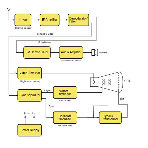
A typical analog monochrome television receiver is based around the block diagram shown below:
Sync separator
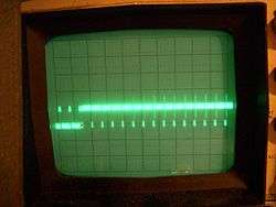
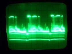
Image synchronization is achieved by transmitting negative-going pulses; in a composite video signal of 1 volt amplitude, these are approximately 0.3 V below the "black level". The horizontal sync signal is a single short pulse which indicates the start of every line. Two timing intervals are defined – the front porch between the end of displayed video and the start of the sync pulse, and the back porch after the sync pulse and before displayed video. These and the sync pulse itself are called the horizontal blanking (or retrace) interval and represent the time that the electron beam in the CRT is returning to the start of the next display line.
The vertical sync signal is a series of much longer pulses, indicating the start of a new field. The sync pulses occupy the whole of line interval of a number of lines at the beginning and end of a scan; no picture information is transmitted during vertical retrace. The pulse sequence is designed to allow horizontal sync to continue during vertical retrace; it also indicates whether each field represents even or odd lines in interlaced systems (depending on whether it begins at the start of a horizontal line, or midway through).
In the television receiver, a sync separator circuit detects the sync voltage levels and sorts the pulses into horizontal and vertical sync.
Loss of horizontal synchronization usually resulted in an unwatchable picture; loss of vertical synchronization would produce an image rolling up or down the screen.
Timebase circuits
In an analog receiver with a CRT display sync pulses are fed to horizontal and vertical timebase circuits (commonly called "sweep circuits" in the United States), each consisting of an oscillator and an amplifier. These generate modified sawtooth and parabola current waveforms to scan the electron beam in a linear way. The waveform shapes are necessary to make up for the distance variations from the electron beam source and the screen surface. The oscillators are designed to free-run at frequencies very close to the field and line rates, but the sync pulses cause them to reset at the beginning of each scan line or field, resulting in the necessary synchronization of the beam sweep with the originating signal. The output waveforms from the timebase amplifiers are fed to the horizontal and vertical deflection coils wrapped around the CRT tube. These coils produce magnetic fields proportional to the changing current, and these deflect the electron beam across the screen.
In the 1950s, the power for these circuits was derived directly from the mains supply. A simple circuit consisted of a series voltage dropper resistance and a rectifier valve (tube) or semiconductor diode. This avoided the cost of a large high voltage mains supply (50 or 60 Hz) transformer. This type of circuit was used for thermionic valve (tube) technology. It was inefficient and produced a lot of heat which led to premature failures in the circuitry.
In the 1960s, semiconductor technology was introduced into timebase circuits. During the late 1960s in the UK, synchronous (with the scan line rate) power generation was introduced into solid state receiver designs.[9] These had very complex circuits in which faults were difficult to trace, but had very efficient use of power.
In the early 1970s AC mains (50 or 60 Hz), and line timebase (15,625 Hz), thyristor based switching circuits were introduced. In the UK use of the simple (50 Hz) types of power circuits were discontinued. The reason for design changes arose from the electricity supply contamination problems arising from EMI,[10] and supply loading issues due to energy being taken from only the positive half cycle of the mains supply waveform.[11]
CRT flyback power supply design and operation principles
Most of the receiver's circuitry (at least in transistor- or IC-based designs) operates from a comparatively low-voltage DC power supply. However, the anode connection for a cathode-ray tube requires a very high voltage (typically 10–30 kV) for correct operation.
This voltage is not directly produced by the main power supply circuitry; instead the receiver makes use of the circuitry used for horizontal scanning. Direct current (DC), is switched though the line output transformer, and alternating current (AC) is induced into the scan coils. At the end of each horizontal scan line the magnetic field, which has built up in both transformer and scan coils by the current, is a source of latent electromagnetic energy. This stored collapsing magnetic field energy can be captured. The reverse flow, short duration, (about 10% of the line scan time) current from both the line output transformer and the horizontal scan coil is discharged again into the primary winding of the flyback transformer by the use of a rectifier which blocks this negative reverse emf. A small value capacitor is connected across the scan switching device. This tunes the circuit inductances to resonate at a much higher frequency. This slows down (lengthens) the flyback time from the extremely rapid decay rate that would result if they were electrically isolated during this short period. One of the secondary windings on the flyback transformer then feeds this brief high voltage pulse to a Cockcroft–Walton generator design voltage multiplier. This produces the required EHT supply. A flyback converter is a power supply circuit operating on similar principles.
A typical modern design incorporates the flyback transformer and rectifier circuitry into a single unit with a captive output lead, (known as a diode split line output transformer or an Integrated High Voltage Transformer (IHVT)),[12] so that all high-voltage parts are enclosed. Earlier designs used a separate line output transformer and a well insulated high voltage multiplier unit. The high frequency (15 kHz or so) of the horizontal scanning allows reasonably small components to be used.
Transition to digital
The first country to make a wholesale switch to digital over-the-air (terrestrial television) broadcasting was Luxembourg in 2006, followed later in 2006 by the Netherlands; in 2007 by Finland, Andorra, Sweden and Switzerland; in 2008 by Belgium (Flanders) and Germany; in 2009 by the United States (high power stations), southern Canada, the Isle of Man, Norway, and Denmark. In 2010, Belgium (Wallonia), Spain, Wales, Latvia, Estonia, the Channel Islands, San Marino and Slovenia; in 2011 Israel, Austria, Monaco, Cyprus, Japan (excluding Miyagi, Iwate, and Fukushima Prefectures), Malta and France; in 2012 Czech Republic, Arab World, Taiwan, Portugal, Japan (including Miyagi, Iwate, and Fukushima Prefectures), Serbia, Italy, Canada, Mauritius, United Kingdom, Republic of Ireland, Lithuania, Slovakia, Gibraltar, South Korea; in 2013, Republic of Macedonia, Poland, Bulgaria, Hungary, Australia, New Zealand, completed the transition. The United Kingdom made the transition to digital television between 2008 and 2012, with the exception of Barrow-in-Furness, which made the switch over in 2007. The first Digital TV only area in the United Kingdom was Ferryside in Carmarthenshire.
In the United States, high-power over-the-air broadcasts are solely in the ATSC digital format since 12 June 2009, the date that the Federal Communications Commission (FCC) set for the end of all high-power analog television transmissions. As a result, almost two million households could no longer watch television because they had not prepared for the transition. The switchover was originally scheduled for 17 February 2009, until the U.S. Congress passed the DTV Delay Act.[13] By special dispensation, some analog television signals ceased on the original date.[14] While the majority of the viewers of over-the-air broadcast television in the U.S. watch full-power stations (which number about 1800), there are three other categories of television stations in the U.S.: low-power broadcasting stations, Class A stations, and television translator stations. There is presently no deadline for these stations, about 7100 in number, to convert to digital broadcasting. In broadcasting, whatever happens in the United States also influences southern Canada and northern Mexico because those areas are covered by television stations in the U.S.
In Japan, the switch to digital occurred on the 24 July 2011, but in Fukushima, Iwate, and Miyagi prefectures, the conversion was delayed to 31 March 2012, due to complications from the 2011 Tōhoku earthquake and tsunami and its related nuclear accidents. In Canada, most of the larger cities turned off analog broadcasts on 31 August 2011.[15] China is scheduled to end analog broadcasting between 2015 and 2018, due to the large size of the country.
Brazil switched to digital television on 2 December 2007 in its major cities. It is now estimated that Brazil will end analog broadcasting in 2023.
In Malaysia, the Malaysian Communications & Multimedia Commission (MCMC) advertised for tender bids to be submitted in the third quarter of 2009 for the 470 through 742 MHz UHF allocation, to enable Malaysia's broadcast system to move into DTV. The new broadcast band allocation would result in Malaysia's having to build an infrastructure for all broadcasters, using a single digital terrestrial transmission/television broadcast (DTTB) channel. Large portions of Malaysia are covered by television broadcasts from Singapore, Thailand, Brunei, and/or Indonesia (from Borneo and Batam)
In the Philippines, the National Telecommunications Commission required all broadcasting companies to end analog broadcasting on December 31, 2015 11:59 p.m. Due to delay of the release of the implementing rules and regulations for digital television broadcast, the target date was moved to 2020. Full digital broadcast is expected in 2021.
See also
External links
- Video signal measurement and generation
- Television synchronisation
- Video broadcast standard frequencies and country listings
- EDN magazine describing design of a 1958 transistorised television receiver
- Designing the color television signal in the early 1950s as described by two engineers working directly with the NTSC
References
- ↑ "Television Technical Performance Code" (PDF). Ofcom – office of Communications. December 2006. Retrieved 24 November 2010.
- ↑ "TV Technology PAL". Publication date unknown. Thinkbox. Archived from the original on 5 December 2010. Retrieved 24 November 2010.
- ↑ "Color Television History". Publication date unknown. About.com. Retrieved 24 November 2010.
- ↑ "Color subcarrier frequency and TV Standards/TV Systems". Publication dates 2002, 2003, 2004, 2005 last updated 2005/12/15. Paradiso Design. Retrieved 24 November 2010.
- ↑ "Pal systems – Television measurements" (PDF). Publication date September 1999. Tektronics Incorporated. Retrieved 25 November 2010.
- 1 2 3 Gupta, R. G. (2006). Television Engineering and Video Systems. Tata McGraw-Hill. p. 62. ISBN 0-07-058596-2.
- 1 2 3 Pemberton, Alan (30 November 2008). "World Analogue Television Standards and Waveforms". Pembers' Ponderings. Sheffield, England. Archived from the original on 20 Feb 2008. Retrieved 25 September 2010.
- ↑ Wharton, W.; Douglas Howorth (1971). Principles of Television Reception (illustrated ed.). Pitman Publishing. ISBN 0-273-36103-1. OCLC 16244216.
- ↑ "TACKLING THE POWER SUPPLY". Publication date – unknown. Old Tellys.co.uk. Retrieved 24 November 2010.
- ↑ "An Investigation Into the EMC Emissions From Switched Mode Power Supplies and Similar Switched Electronic Load Contollers Operating at Various Loading Conditions – Page 2,line 3" (PDF). Publication date – January 2001. York EMC.co.uk. Retrieved 24 November 2010.
- ↑ "Review of Primary Frequency Control Requirements on the GB Power System Against a Background of Increase in Renewable Generation – Impact of railway electrification systems on other electrical systems and civil infrastructures within and outside the railway environment.-section 3.2,page 15" (PDF). October 2006. Bura.Brunel.ac.uk. Retrieved 24 November 2010.
- ↑ "Technical note 77 – Diode Split for E.H.T. generation" (PDF). Publication date – 1976. Mullard. Retrieved 24 November 2010.
- ↑ Stephanie Condon (26 January 2009). "Senate OKs delay of digital television transition". CNET News. Retrieved 14 June 2009.
- ↑ Across Nation, Some TV Stations Go Digital Tonight
- ↑ http://www.crtc.gc.ca/eng/info_sht/bdt14.htm