Jerk (physics)
In physics, jerk, also known as jolt, surge, or lurch, is the rate of change of acceleration; that is, the derivative of acceleration with respect to time, and as such the second derivative of velocity, or the third derivative of position. Jerk is a vector, and there is no generally used term to describe its scalar magnitude (more precisely, its norm, e.g. "speed" as the norm of the velocity vector). According to the result of dimensional analysis of jerk, [length/time3], the SI units are m/s3 (or m·s−3); jerk can also be expressed in standard gravity per second (g/s).
Expressions
Jerk can be formulated in any of the following equivalent ways:

where
- is acceleration,
- is velocity,
- is position,
- is time.


There is no universal agreement on the symbol for jerk, but is commonly used. Newton's notation for the time derivative () is also applied.


The fourth derivative of position, equivalent to the first derivative of jerk, is jounce.
Because of involving third derivatives, in mathematics differential equations of the form

are called jerk equations. It has been shown that a jerk equation, which is equivalent to a system of three first-order ordinary non-linear differential equations, is in a mathematically well defined sense the minimal setting for solutions showing chaotic behaviour. This motivates mathematical interest in jerk systems. Systems involving a fourth or higher derivative are accordingly called hyperjerk systems.
Physiological effects and human perception
The smooth movement and also the rest state of an alert human body is achieved by balancing the forces of several antagonistic muscles which are controlled across neural paths by the brain (for directed movement) or sometimes across reflex arcs. In balancing some given force (holding or pulling up a weight, e.g.) the postcentral gyrus establishes a control loop to achieve this equilibrium by adjusting the muscular tension according to the sensed position of the actuator. If the load changes faster than the current state of this control loop is capable of supplying a suitable, adaptive response, the balance cannot be upheld, because the tensioned muscles cannot relax or build up tension fast enough and overshoot in either direction, until the neural control loop manages to take control again. Of course the time to react is limited from below by physiological bounds and also depends on the attention level of the brain: an expected change will be stabilized faster than a sudden drop or increase of load.
So passengers in transportation, who need this time to adapt to stress changes and to adjust their muscle tension, or else suffer conditions such as whiplash, can be safely subjected both only to a less than maximum acceleration, and to a less than maximum jerk,[1] so to avoid loss of control over their body motion thereby endangering their physical integrity. Even where occupant safety is not an issue, excessive jerk may result in an uncomfortable ride on elevators, trams, and the like, and engineers expend considerable design effort to minimize "jerky motion".
Since forces, changing at a suitable rate in time (that is, suitable jerk) are the cause of vibrations, and vibrations significantly impair the quality of transportation, there is good reason to simply minimize jerk in transportation vehicles.
As an everyday example, driving in a car can show effects of acceleration and jerk. The more experienced drivers accelerate smoothly, but beginners provide a jerky ride.
- Changing gears, especially with a foot-operated clutch, offers well-known examples: although the accelerating force is bounded by the engine power, an inexperienced driver lets you experience severe jerk, because of intermittent force closure over the clutch.
- High-powered sports cars offer the feeling of being pressed into the cushioning, but this is the force of the acceleration. Only in the very first moments, when the torque of the engine grows with the rotational speed, the acceleration grows remarkably and a slight whiplash effect is noticeable in the neck, mostly masked by the jerk of gear switching.
- The beginning of an emergency braking lets the body whip forward faster than the achieved acceleration value alone would accomplish, and a collision does so to an even greater degree, but quantitative testing on living humans (and, for some, on animals) runs afoul of ethical concerns, with the effect that cadavers or crash test dummies must be substituted, which, of course, do not show the physiological reactions to jerk caused by an active control loop described above.
- A highly reproducible experiment to demonstrate jerk is as follows: Brake a car starting at a modest speed in two different ways:
- apply a constant, modest force on the pedal till the car comes to a halt, only then release the pedal;
- apply the same, constant, modest force on the pedal, but just before the halt, reduce the force on the pedal, optimally releasing the pedal fully, exactly when the car stops.
- The reason for the by far bigger jerk in the first way to brake is a discontinuity of the acceleration, which is initially at a constant value, due to the constant force on the pedal, and drops to zero immediately, when the wheels stop rotating. Note that there would be no jerk if the car started to move backwards with the same acceleration. Every experienced driver knows how to start and how to stop braking with low jerk. See also below in the motion profile, segment 7: Deceleration ramp-down.
For some remarks on how the human perception of various motions is organized in the proprioceptors, the vestibular organ and by visual impressions, and how to deceive it, see the article on motion simulators.
Forces and path derivatives
Position itself, zeroth derivative

The most prominent force associated with the position of a particle relates through Hooke's law to the rigid stiffness of a spring:


This is a force opposing the increase in displacement.
Speed , magnitude of the first derivative

A particle moving in a viscous fluid environment experiences a drag force , which, depending on the Reynolds number and its area, ranges from being proportional to up to being proportional to according to the drag equation:


where
- is the density of the fluid,
- is the speed of the object relative to the fluid,
- is the cross-sectional area,
- is the drag coefficient – a dimensionless number.


The drag coefficient depends on the scalable shape of the object and on the Reynolds number, which itself depends on the speed.
Acceleration a, magnitude of the second derivative
The acceleration is according to Newton's second law


bound to a force by the proportionality given by the mass .

Higher derivatives
In classical mechanics of rigid bodies there are no forces associated with the higher derivatives of the path, nevertheless not only the physiological effects of jerk, but also oscillations and deformation propagation along and in non-ideally rigid bodies, require various techniques for controlling motion to avoid the resulting destructive forces. It is often reported that NASA in designing the Hubble Telescope not only limited the jerk in their requirement specification, but also the next higher derivative, the jounce.
For a recoil force on accelerating charged particles emitting radiation, which is proportional to their jerk and the square of their charge, see the Abraham–Lorentz force. A more advanced theory, applicable in a relativistic and quantum environment, accounting for self-energy is provided in Wheeler–Feynman absorber theory.
In an idealized setting
In real world environments, because of deformation, granularity at least at the Planck scale, i.e. quanta-effects, and other reasons, discontinuities in acceleration do not occur. However, frequently used idealized settings (rigid bodies, smooth representations of paths, no friction, and the like) applied to an also idealized point mass moving along a piecewise smooth and as a whole continuous path, suffice for the phenomenon of a jump-discontinuity in acceleration at the points where the path is not smooth, and accordingly for an unbounded jerk in this simplified model of classical mechanics (see two examples below). Extrapolating from the idealized settings, the effect of jerk in real situations can be qualitatively described, explained and predicted.
The jump-discontinuity in acceleration may be modeled by a Dirac delta in the jerk, scaled with the height of this jump. Integrating jerk over time generally gives the according acceleration; doing so across such a Dirac delta reconstructs exactly the jump discontinuity in the acceleration belonging to the Dirac delta in the jerk.
Assume a path along a circular arc with radius , which tangentially connects to a straight line. The whole path is continuous and its pieces are smooth. Now let a point particle move with constant speed along this path, so its tangential acceleration is zero, and consider the acceleration orthogonal to the path: it is zero along the straight part and along the circle (centripetal acceleration). This gives a jump-discontinuity in the magnitude of the acceleration by , and the particle undergoes a jerk measured by a Dirac delta scaled with this value, for purely geometric reasons, when it passes the connection of the pieces. See below for a more concrete application.


If we assume an idealized spring and idealized, kinetic frictional forces, proportional to the normal force and directed oppositely to the velocity, there is another example of discontinuous acceleration. Let a mass, connected to an ideal spring, oscillate on a flat, idealized surface with friction. Each time the velocity changes sign (at the maxima of displacement), the magnitude of the force on the mass, which is the vectorial sum of the spring force and the kinetic frictional force, changes by twice the magnitude of the frictional force, since the spring force is continuous and the frictional force reverses its direction when the velocity does. Therefore the acceleration jumps by this amount divided by the mass. That is, the mass experiences a discontinuous acceleration and the jerk contains a Dirac delta, each time the mass passes through the (decreasing) maximal displacements, until it comes to a halt, because the static friction force adapts to the residual spring force, establishing equilibrium with zero net force and zero velocity.
The car example relies on the way the brakes operate on a rotating drum or on a disc. As long as the disc rotates the brake pads act to decelerate the vehicle via the kinetic frictional forces which create a constant braking torque on the disk. This decreases the rotation linearly to zero with constant angular acceleration, but when the rotation reaches exactly zero, this hitherto constant frictional force suddenly drops to zero, as well as the torque, and the associated acceleration of the car. This, of course, neglects all effects of tire sliding, dipping of suspension, real deflection of all ideally rigid mechanisms, etc. A sudden drop in acceleration indicates a Dirac delta in the physical jerk, which is smoothed down by the real environment, the cumulative effects of which are analogous to damping, to the physiologically perceived jerk.
Another example of significant jerk, analogous to the first setting, is given by cutting the rope twirling a particle around a center. When the rope is cut, the circular path with non-zero centripetal acceleration changes abruptly to a straight path with suddenly no force in the direction to the former center. Imagine a monomolecular fiber, cut by a laser and you arrive at very high rates of jerk, because of the extremely short cutting time.
In rotation


Consider a rotational movement of a rigid body about a fixed axis in an inertial frame. The orientation of the solid can be expressed by an angle , the angular position, from which one can express:

- the angular speed as the time derivative of
- the angular acceleration as the time derivative of .


Differentiating the with respect to time, defines an angular jerk :


- .

The angular acceleration corresponds to the quotient of the torque acting on the body and the moment of inertia of the body with respect to the momentary axis of rotation. An abrupt change of the torque results in an important angular jerk.
The general case of a rigid body movement in space can be modeled by a kinematic screw, which specifies at each instant one (axial) vector, the angular velocity and one (polar) vector, the linear velocity . From this the angular acceleration is defined as


and thus the angular jerk
- .

Consider for example a Geneva drive, a device for creating an intermittent rotation of the driven wheel (blue) from a continuous rotation of the driving wheel (red). On one cycle of the driving wheel there is a variation of the angular position of the driven wheel by one quarter of a cycle, and a constant angular position on the remainder of the cycle.
Because of the necessary finite thickness of the fork making up the slot for the driving pin this device generates a discontinuity in the angular acceleration , and therefore an unbounded angular jerk in the driven wheel.


This does not preclude the mechanism from being used in e.g. movie projectors to stepwise transport the film with high reliability (very long life) and just slight noise, since the load is very low - the system drives just that part of the film which is within the corridor of projection, so a very low mass (a few centimeters thin plastic film), with low friction, at a moderate speed (2.4 m/s, 8.6 km/h) is affected.
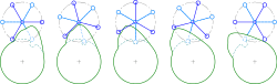
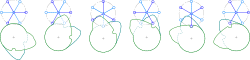
To avoid the jerk inherent in a single cam device, a dual cam device can be used instead, bulkier and more expensive, but also quieter. This operates two cams on one axis in continuous rotation and shifting another axle about a fraction of a full revolution. The pictures show a step drive by one sixth and one third rotation, respectively per full revolution of the driving axle. Note that two of the arms of the stepped wheel are always in contact with the double cam, so there is no radial clearance. To follow the detailed operation of the dual cam devices it is advisable to have a look at the enlarged pictures.
Generally, combined contacts may be used to avoid jerk (and also wear and noise) associated with one single follower, e.g. gliding along a slot and thereby changing its contact point from one side of the slot to the other, by using two followers always sliding along the same, one side each.
In elastically deformable matter
A force/acceleration acting on an elastically deformable mass will affect a deformation which depends on its stiffness and the acceleration applied. If the change of this force is slow, the jerk is small, and the propagation of this deformation through the body may be considered instantaneously compared to the change in acceleration. The distorted body acts as if it were in a quasi-static regime. It is the common thread that only a changing force, i.e. a non-zero jerk, can cause mechanical (or on a charged particle: electromagnetic) waves to be radiated. So for non-zero to high jerk a shock wave and its propagation through the body is to be considered. The left picture shows the propagation of a deformation as a compressional, plane wave through an elastically deformable material. For angular jerk the deformation waves are arranged circularly and cause shear stress as shown in the adjacent picture, which also might cause other modes of vibration. As usual with waves, one has to consider their reflections along all boundaries and the emerging interference patterns, i.e. destructive as well as constructive interference, which may lead to exceeding boundaries of structural integrity. As a rough estimate the deformation waves result in vibrations of the whole device and, generally, vibrations cause noise, wear, and, especially in resonance cases, even disruption.
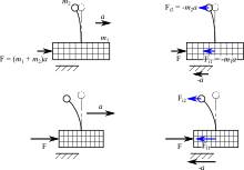
The picture to the left shows a massive top bending the elastic pole, to which it is connected, to the left, when the bottom block is accelerated to the right. When the block stops accelerating, the top on the pole will start a (damped) oscillation under the regime of the stiffness of the pole. This could make plausible, how a bigger (periodic) jerk might excite a bigger amplitude of the oscillations, because any small oscillations are damped before they get reinforced by another amplitude of the shock wave.
One can also argue that a steeper slope of the acceleration, i.e. a bigger jerk, excites bigger wave components in the shockwave with higher frequencies, belonging to higher Fourier coefficients, and so an increased probability of exciting a resonant mode.
As a general rule, to reduce the amplitude of excited stress waves, causing vibrations, any motion of massive parts has to be shaped by limiting the jerk, i.e. making the acceleration continuous and keep its slopes as flat as possible. Since the described effects are almost not amenable to abstract models anymore, the various suggested algorithms for reducing vibrations include still higher derivatives such as the jounce or suggest continuous regimes not only for the acceleration, but also for the jerk. One concept is e.g. shaping the acceleration and deceleration sinusoidal with zero-acceleration in between (see the profile to the right), making the speed look sinusoidal with constant maximal speed, too. The jerk however will remain discontinuous at the points when the acceleration enters and leaves its zero-phases.
In the geometric design of roads and tracks

The principles of geometric design apply to the jerk oriented orthogonally to the path of motion, considering the centripetal acceleration, whereas the velocity along the path is assumed to be constant, and so the tangential jerk is zero. Any change in curvature of the path implies non-zero jerk, arising from purely geometric reasons. To avoid the unbounded (centripetal) jerk when moving from a straight path into a curve or vice versa, track transition curves are constructed, which limit the jerk by gradually increasing the centripetal acceleration, i.e. the curvature, to the value that belongs to the radius of the circle and the speed of travel. The theoretical optimum is achieved by the Euler spiral, which linearly increases the acceleration, i.e. minimal constant jerk. As a design rule a maximum value of 0.5 m/s3 and for convenience purposes a value of 0.35 m/s3 are recommended in railway design. The picture shows a piece of an Euler spiral leading as track transition curve from a straight line to an arc of a circle. In the real scenario the plane of the track is inclined in the course of the curve and so also this vertical acceleration of the necessary lifting of the center of mass of the rail car has to be considered to minimize the wear on the embankment and the tracks by following a slightly different curve. This has been patented as the Wiener Kurve (Viennese Curve).[2][3]
Roller coasters[1] are of course also subject to these design considerations, when rolling into a loop. The acceleration values range up to 4g in this environment and it would not be possible to ride loopings without track transitions, as well as one cannot smoothly drive along a figure eight consisting of circles. Any S-shaped curve must contain some jerk-reducing transition.
In motion control
In motion control the focus is on straight linear motion, where the need is to move a system from one steady position to another (point-to-point motion). So effectively, the jerk resulting from tangential acceleration is under control. Prominent applications are elevators in people transportation, and the support of tools in machining. It is reported[4] that most passengers rate a vertical jerk of 2.0 m/s3 in a lift ride as acceptable, 6.0 m/s3 as intolerable and for a hospital environment 0.7 m/s3 is suggested. In any case, limiting jerk is considered essential for riding convenience.[5] ISO 18 738[6] defines how to measure elevator ride quality with respect to jerk, acceleration, vibrations and noise, but does not venture into defining what are different levels of elevator ride quality.
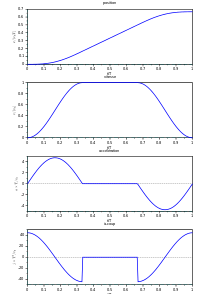
Achieving the shortest possible transition time, thereby not exceeding given limit magnitudes for speed, acceleration, and jerk, will result in a third-order motion profile, with quadratic ramping and de-ramping phases in the velocity, as illustrated below:
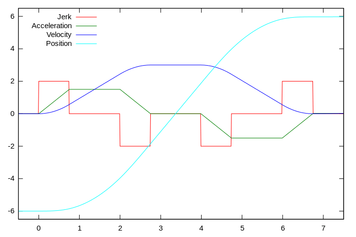
This motion profile consists of up to seven segments defined by the following:
- acceleration build-up: limit jerk implies linear increase of acceleration to the limit acceleration, quadratic increase of speed
- limit acceleration: implies zero jerk and linear increase of speed
- acceleration ramp-down: approaching the desired limit velocity with negative limit jerk, i.e. linear decrease of acceleration, (negative) quadratic increase of speed
- limit speed: implies zero jerk and zero acceleration
- deceleration build-up: limit negative jerk implies linear decrease of acceleration to the negative limit acceleration, (negative) quadratic decrease of speed
- limit deceleration: implies zero jerk and linear decrease of speed
- deceleration ramp-down: limit jerk implies linear increase of acceleration to zero, quadratic decrease of speed, approaching the desired position at zero speed and zero acceleration
The time allotted to segment 4, concerning constant velocity, is to be varied to suit the distance between the two positions. If the initial and final positions are so close together that a complete omission of this 4. segment does not suffice, the segments 2. and 6. with constant acceleration are equally reduced and the limit of speed would not be reached in this variant of the profile. If also this does not reduce the crossed distance sufficiently, in a next step the ramping segments 1., 3., 5., and 7. are to be shortened by an equal amount and the limit of acceleration is not reached, also.
There are also other strategies to design a motion profile, e.g. minimizing the square of the jerk for a given transition time, to be selected according to the varying applications in machines, people movers, chain hoists, automotive industries, robot design, and many more. For a sinusoidal-shaped acceleration profile, with sinusoidal-shaped speed and bounded jerk also, see above.
In manufacturing
Jerk is also important to consider in manufacturing processes. Rapid changes in acceleration of a cutting tool can lead to premature tool wear and result in uneven cuts. This is why modern motion controllers include jerk limitation features. In mechanical engineering, jerk is considered, in addition to velocity and acceleration, in the development of cam profiles because of tribological implications and the ability of the actuated body to follow the cam profile without chatter.[7] Jerk must be often considered when the excitation of vibrations is a concern. A device that measures jerk is called a "jerkmeter".
See also
- Jounce, the derivative of jerk
- Geomagnetic jerk
- Abraham–Lorentz force, a force in electrodynamics whose magnitude is proportional to jerk
- Shock (mechanics)
- Wheeler–Feynman absorber theory
Notes
- 1 2 "How Things Work: Roller Coasters - The Tartan Online". Thetartan.org. 2007-04-16. Retrieved 2013-09-15.
- ↑ https://depatisnet.dpma.de/DepatisNet/depatisnet?window=1&space=menu&content=treffer&action=pdf&docid=AT000000412975B
- ↑ http://www.mplusm.at/ifg/download/Presle-05.pdf
- ↑ Howkins, Roger E. "Elevator Ride Quality - The Human Ride Experience". VFZ-Verlag für Zielgruppeninformationen GmbH & Co. KG. Retrieved 31 December 2014.
- ↑ http://www.schindler.com/content/ie/internet/en/mobility-solutions/products/elevators/schindler-5300/_jcr_content/rightPar/downloadlist/downloadList/3_1340031711862.download.asset.3_1340031711862/05SML9039_Inform_Sheet_EN.pdf
- ↑ ISO 18738-1:2012. "Measurement of ride quality -- Part 1: Lifts (elevators)". International Organization for Standardization. Retrieved 31 December 2014.
- ↑ Blair, G., "Making the Cam", Race Engine Technology 10, September/October 2005
References
- Sprott JC (2003). Chaos and Time-Series Analysis. Oxford University Press. ISBN 0-19-850839-5.
- Sprott JC (1997). "Some simple chaotic jerk functions" (PDF). Am J Phys. 65 (6): 537–43. Bibcode:1997AmJPh..65..537S. doi:10.1119/1.18585. Retrieved 2009-09-28.
- Blair G (2005). "Making the Cam" (PDF). Race Engine Technology (010). Retrieved 2009-09-29.
External links
- What is the term used for the third derivative of position?, description of jerk in the Usenet Physics FAQ
- Mathematics of Motion Control Profiles
- Elevator ride quality
- Elevator manufacturer brochure
- Patent of Wiener Kurve
- (German) Description of Wiener Kurve