Moment of inertia
| Classical mechanics |
|---|
|
Core topics |


The moment of inertia, otherwise known as the angular mass or rotational inertia, of a rigid body is a tensor that determines the torque needed for a desired angular acceleration about a rotational axis. It depends on the body's mass distribution and the axis chosen, with larger moments requiring more torque to change the body's rotation. It is an extensive (additive) property: the moment of inertia of a composite system is the sum of the moments of inertia of its component subsystems (all taken about the same axis). One of its definitions is the second moment of mass with respect to distance from an axis r, , integrating over the entire mass .


For bodies constrained to rotate in a plane, it is sufficient to consider their moment of inertia about an axis perpendicular to the plane. For bodies free to rotate in three dimensions, their moments can be described by a symmetric 3 × 3 matrix; each body has a set of mutually perpendicular principal axes for which this matrix is diagonal and torques around the axes act independently of each other.
Introduction
When a body is rotating, or free to rotate, around an axis, a torque must be applied to change its angular momentum. The amount of torque needed for any given rate of change in angular momentum is proportional to the moment of inertia of the body. Moment of inertia may be expressed in terms of kilogram-square metres (kg·m2) in SI units and pound-square feet (lbm·ft2) in imperial or US units.
Moment of inertia plays the role in rotational kinetics that mass (inertia) plays in linear kinetics - both characterize the resistance of a body to changes in its motion. The moment of inertia depends on how mass is distributed around an axis of rotation, and will vary depending on the chosen axis. For a point-like mass, the moment of inertia about some axis is given by d2m, where d is the distance to the axis, and m is the mass. For an extended body, the moment of inertia is just the sum of all the small pieces of mass multiplied by the square of their distances from the axis in question. For an extended body of a regular shape and uniform density, this summation sometimes produces a simple expression that depends on the dimensions, shape and total mass of the object.
In 1673 Christiaan Huygens introduced this parameter in his study of the oscillation of a body hanging from a pivot, known as a compound pendulum.[1] The term moment of inertia was introduced by Leonhard Euler in his book Theoria motus corporum solidorum seu rigidorum in 1765,[1][2] and it is incorporated into Euler's second law.
The natural frequency of oscillation of a compound pendulum is obtained from the ratio of the torque imposed by gravity on the mass of the pendulum to the resistance to acceleration defined by the moment of inertia. Comparison of this natural frequency to that of a simple pendulum consisting of a single point of mass provides a mathematical formulation for moment of inertia of an extended body.[3][4]
Moment of inertia also appears in momentum, kinetic energy, and in Newton's laws of motion for a rigid body as a physical parameter that combines its shape and mass. There is an interesting difference in the way moment of inertia appears in planar and spatial movement. Planar movement has a single scalar that defines the moment of inertia, while for spatial movement the same calculations yield a 3 × 3 matrix of moments of inertia, called the inertia matrix or inertia tensor.[5][6]
The moment of inertia of a rotating flywheel is used in a machine to resist variations in applied torque to smooth its rotational output. The moment of inertia of an airplane about its longitudinal, horizontal and vertical axis determines how steering forces on the control surfaces of its wings, elevators and tail affect the plane in roll, pitch and yaw.
Definition
.jpg)

Moment of inertia I is defined as the ratio of the angular momentum L of a system to its angular velocity ω around a principal axis, that is[7][8]

If the angular momentum of a system is constant, then as the moment of inertia gets smaller, the angular velocity must increase. This occurs when spinning figure skaters pull in their outstretched arms or divers curl their bodies into a tuck position during a dive, to spin faster.[7][8][9][10][11][12][13]
If the shape of the body does not change, then its moment of inertia appears in Newton's law of motion as the ratio of an applied torque τ on a body to the angular acceleration α around a principal axis, that is

For a simple pendulum, this definition yields a formula for the moment of inertia I in terms of the mass m of the pendulum and its distance r from the pivot point as,

Thus, moment of inertia depends on both the mass m of a body and its geometry, or shape, as defined by the distance r to the axis of rotation.
This simple formula generalizes to define moment of inertia for an arbitrarily shaped body as the sum of all the elemental point masses dm each multiplied by the square of its perpendicular distance r to an axis S .
In general, given an object of mass m, an effective radius k can be defined for an axis through its center of mass, with such a value that its moment of inertia is

where k is known as the radius of gyration.
Simple pendulum
Moment of inertia can be measured using a simple pendulum, because it is the resistance to the rotation caused by gravity. Mathematically, the moment of inertia of the pendulum is the ratio of the torque due to gravity about the pivot of a pendulum to its angular acceleration about that pivot point. For a simple pendulum this is found to be the product of the mass of the particle m with the square of its distance r to the pivot, that is
This can be shown as follows: The force of gravity on the mass of a simple pendulum generates a torque around the axis perpendicular to the plane of the pendulum movement. Here r is the distance vector perpendicular to and from the force to the torque axis. Here F is the tangential component of the net force on the mass. Associated with this torque is an angular acceleration, , of the string and mass around this axis. Since the mass is constrained to a circle the tangential acceleration of the mass is . Since the torque equation becomes:


where e is a unit vector perpendicular to the plane of the pendulum. (The second to the last step occurs because of the BAC-CAB rule using the fact that is always perpendicular to r.) The quantity I = mr2 is the moment of inertia of this single mass around the pivot point.
The quantity I = mr2 also appears in the angular momentum of a simple pendulum, which is calculated from the velocity v = ω×r of the pendulum mass around the pivot, where ω is the angular velocity of the mass about the pivot point. This angular momentum is given by

using math similar to that used to derive the previous equation.
Similarly, the kinetic energy of the pendulum mass is defined by the velocity of the pendulum around the pivot to yield

This shows that the quantity I = mr2 is how mass combines with the shape of a body to define rotational inertia. The moment of inertia of an arbitrarily shaped body is the sum of the values mr2 for all of the elements of mass in the body.
Compound pendulum

A compound pendulum is a body formed from an assembly of particles of continuous shape that rotates rigidly around a pivot. Its moment of inertia is the sum of the moments of inertia of each of the particles that it is composed of.[14][15]:395–396[16]:51–53 The natural frequency () of a compound pendulum depends on its moment of inertia, ,


where is the mass of the object, is local acceleration of gravity, and is the distance from the pivot point to the centre of mass of the object. Measuring this frequency of oscillation over small angular displacements provides an effective way of measuring moment of inertia of a body.[17]:516–517


Thus, to determine the moment of inertia of the body, simply suspend it from a convenient pivot point so that it swings freely in a plane perpendicular to the direction of the desired moment of inertia, then measure its natural frequency or period of oscillation (), to obtain


where is the period (duration) of oscillation (usually averaged over multiple periods).
The moment of inertia of the body about its centre of mass, , is then calculated using the parallel axis theorem to be


where is the mass of the body and is the distance from the pivot point to the centre of mass .

Moment of inertia of a body is often defined in terms of its radius of gyration, which is the radius of a ring of equal mass around the centre of mass of a body that has the same moment of inertia. The radius of gyration is calculated from the body's moment of inertia and mass as the length,[18]:1296–1297


Center of oscillation
A simple pendulum that has the same natural frequency as a compound pendulum defines the length from the pivot to a point called the centre of oscillation of the compound pendulum. This point also corresponds to the centre of percussion. The length is determined from the formula,


or

The seconds pendulum, which provides the "tick" and "tock" of a grandfather clock, takes one second to swing from side-to-side. This is a period of two seconds, or a natural frequency of π radians/second for the pendulum. In this case, the distance to the center of oscillation, , can be computed to be

Notice that the distance to the center of oscillation of the seconds pendulum must be adjusted to accommodate different values for the local acceleration of gravity. Kater's pendulum is a compound pendulum that uses this property to measure the local acceleration of gravity, and is called a gravimeter.
Measuring moment of inertia
The moment of inertia of complex systems such as a vehicle or airplane around its vertical axis can be measured by suspending the system from three points to form a trifilar pendulum. A trifilar pendulum is a platform supported by three wires designed to oscillate in torsion around its vertical centroidal axis.[19] The period of oscillation of the trifilar pendulum yields the moment of inertia of the system.[20]
Calculating moment of inertia about an axis
The moment of inertia about an axis of a body is calculated by summing mr2 for every particle in the body, where r is the perpendicular distance to the specified axis. To see how moment of inertia arises in the study of the movement of an extended body, it is convenient to consider a rigid assembly of point masses. (This equation can be used for axes that are not principal axes provided that it is understood that this does not fully describe the moment of inertia.[21])
Consider the kinetic energy of an assembly of N masses mi that lie at the distances ri from the pivot point P, which is the nearest point on the axis of rotation. It is the sum of the kinetic energy of the individual masses,[17]:516–517[18]:1084–1085 [18]:1296–1300

This shows that the moment of inertia of the body is the sum of each of the mr2 terms, that is

Thus, moment of inertia is a physical property that combines the mass and distribution of the particles around the rotation axis. Notice that rotation about different axes of the same body yield different moments of inertia.
The moment of inertia of a continuous body rotating about a specified axis is calculated in the same way, except with infinitely many point particles. Thus the limits of summation are removed, and the sum is written as follows:

Another expression replaces the summation with an integral,

Here, the function ρ gives the mass density at each point (x, y, z), r is a vector perpendicular to the axis of rotation and extending from a point on the rotation axis to a point (x, y, z) in the solid, and the integration is evaluated over the volume V of the body Q. The moment of inertia of a flat surface is similar with the mass density being replaced by its areal mass density with the integral evaluated over its area.
Note on second moment of area: The moment of inertia of a body moving in a plane and the second moment of area of a beam's cross-section are often confused. The moment of inertia of body with the shape of the cross-section is the second moment of this area about the z-axis perpendicular to the cross-section, weighted by its density. This is also called the polar moment of the area, and is the sum of the second moments about the x and y axes.[22] The stresses in a beam are calculated using the second moment of the cross-sectional area around either the x-axis or y-axis depending on the load.
Example calculation of moment of inertia

The moment of inertia of a compound pendulum constructed from a thin disc mounted at the end of a thin rod that oscillates around a pivot at the other end of the rod, begins with the calculation of the moment of inertia of the thin rod and thin disc about their respective centres of mass.[18]
- The moment of inertia of a thin rod with constant cross-section s and density ρ and with length ℓ about a perpendicular axis through its centre of mass is determined by integration.[18]:1301 Align the x-axis with the rod and locate the origin its centre of mass at the centre of the rod, then

where m = ρsℓ is the mass of the rod.
- The moment of inertia of a thin disc of constant thickness s, radius R, and density ρ about an axis through its centre and perpendicular to its face (parallel to its axis of rotational symmetry) is determined by integration.[18]:1301 Align the z-axis with the axis of the disc and define a volume element as dV = sr drdθ, then

where m = πR2ρs is its mass.
- The moment of inertia of the compound pendulum is now obtained by adding the moment of inertia of the rod and the disc around the pivot point P as,

where L is the length of the pendulum. Notice that the parallel axis theorem is used to shift the moment of inertia from the centre of mass to the pivot point of the pendulum.
A list of moments of inertia formulas for standard body shapes provides a way to obtain the moment of inertia of a complex body as an assembly of simpler shaped bodies. The parallel axis theorem is used to shift the reference point of the individual bodies to the reference point of the assembly.
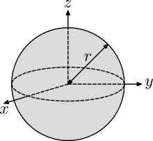
As one more example, consider the moment of inertia of a solid sphere of constant density about an axis through its centre of mass. This is determined by summing the moments of inertia of the thin discs that form the sphere. If the surface of the ball is defined by the equation[18]:1301

then the radius r of the disc at the cross-section z along the z-axis is

Therefore, the moment of inertia of the ball is the sum of the moments of inertia of the discs along the z-axis,

where m = 4/3πR3ρ is the mass of the ball.
Moment of inertia in planar movement of a rigid body
If a mechanical system is constrained to move parallel to a fixed plane, then the rotation of a body in the system occurs around an axis k perpendicular to this plane. In this case, the moment of inertia of the mass in this system is a scalar known as the polar moment of inertia. The definition of the polar moment of inertia can be obtained by considering momentum, kinetic energy and Newton's laws for the planar movement of a rigid system of particles.[14][17][23][24]
If a system of n particles, Pi, i = 1,...,n, are assembled into a rigid body, then the momentum of the system can be written in terms of positions relative to a reference point R, and absolute velocities vi

where ω is the angular velocity of the system and V is the velocity of R.
For planar movement the angular velocity vector is directed along the unit vector k which is perpendicular to the plane of movement. Introduce the unit vectors ei from the reference point R to a point ri , and the unit vector ti = k × ei so

This defines the relative position vector and the velocity vector for the rigid system of the particles moving in a plane.
Note on the cross product: When a body moves parallel to a ground plane, the trajectories of all the points in the body lie in planes parallel to this ground plane. This means that any rotation that the body undergoes must be around an axis perpendicular to this plane. Planar movement is often presented as projected onto this ground plane so that the axis of rotation appears as a point. In this case, the angular velocity and angular acceleration of the body are scalars and the fact that they are vectors along the rotation axis is ignored. This is usually preferred for introductions to the topic. But in the case of moment of inertia, the combination of mass and geometry benefits from the geometric properties of the cross product. For this reason, in this section on planar movement the angular velocity and accelerations of the body are vectors perpendicular to the ground plane, and the cross product operations are the same as used for the study of spatial rigid body movement.
Angular momentum in planar movement
The angular momentum vector for the planar movement of a rigid system of particles is given by[14][17]
![{\begin{aligned}\mathbf {L} &=\sum _{i=1}^{n}\left[m_{i}(\mathbf {r} _{i}-\mathbf {R} )\times \mathbf {v} _{i}\right]\\&=\sum _{i=1}^{n}\left[m_{i}\Delta r_{i}\mathbf {e} _{i}\times (\omega \Delta r_{i}\mathbf {t} _{i}+\mathbf {V} )\right]\\&=\left[\sum _{i=1}^{n}m_{i}\Delta r_{i}^{2}\right]\omega {\vec {k}}+\left[\sum _{i=1}^{n}\left(m_{i}\Delta r_{i}\mathbf {e} _{i}\right)\right]\times \mathbf {V} .\end{aligned}}](../I/m/43081674bdfb858900aec180846d9bca6205c830.svg)
Use the centre of mass C as the reference point so

and define the moment of inertia relative to the centre of mass IC as

then the equation for angular momentum simplifies to[18]:1028

The moment of inertia IC about an axis perpendicular to the movement of the rigid system and through the centre of mass is known as the polar moment of inertia.
For a given amount of angular momentum, a decrease in the moment of inertia results in an increase in the angular velocity. Figure skaters can change their moment of inertia by pulling in their arms. Thus, the angular velocity achieved by a skater with outstretched arms results in a greater angular velocity when the arms are pulled in, because of the reduced moment of inertia. A figure skater is not, however, a rigid body.
Kinetic energy in planar movement

The kinetic energy of a rigid system of particles moving in the plane is given by[14][17]

This equation expands to yield three terms

Let the reference point be the centre of mass C of the system so the second term becomes zero, and introduce the moment of inertia IC so the kinetic energy is given by[18]:1084

The moment of inertia IC is the polar moment of inertia of the body.
Newton's laws for planar movement

Newton's laws for a rigid system of N particles, Pi, i = 1,..., N, can be written in terms of a resultant force and torque at a reference point R, to yield[14][17]

where ri denotes the trajectory of each particle.
The kinematics of a rigid body yields the formula for the acceleration of the particle Pi in terms of the position R and acceleration A of the reference particle as well as the angular velocity vector ω and angular acceleration vector α of the rigid system of particles as,

For systems that are constrained to planar movement, the angular velocity and angular acceleration vectors are directed along k perpendicular to the plane of movement, which simplifies this acceleration equation. In this case, the acceleration vectors can be simplified by introducing the unit vectors ei from the reference point R to a point ri and the unit vectors ti = k × ei , so

This yields the resultant torque on the system as
![{\begin{aligned}{\boldsymbol {\tau }}&=\sum _{i=1}^{N}\left(\left[m_{i}\Delta r_{i}\mathbf {e} _{i}\right]\times \left[\alpha (\Delta r_{i}\mathbf {t} _{i})-\omega ^{2}(\Delta r_{i}\mathbf {e} _{i})+\mathbf {A} \right]\right)\\&=\left(\sum _{i=1}^{N}m_{i}\Delta r_{i}^{2}\right)\alpha {\vec {k}}+\left(\sum _{i=1}^{N}m_{i}\Delta r_{i}\mathbf {e} _{i}\right)\times \mathbf {A} ,\end{aligned}}](../I/m/0eec9b4e4c06f8c025c261e4855cb7426557732c.svg)
where ei × ei = 0, and ei × ti = k is the unit vector perpendicular to the plane for all of the particles Pi .
Use the centre of mass C as the reference point and define the moment of inertia relative to the centre of mass IC , then the equation for the resultant torque simplifies to[18]:1029

The parameter IC is the polar moment of inertia of the moving body.
The inertia matrix for spatial movement of a rigid body
The scalar moments of inertia appear as elements in a matrix when a system of particles is assembled into a rigid body that moves in three-dimensional space. This inertia matrix appears in the calculation of the angular momentum, kinetic energy and resultant torque of the rigid system of particles.[3][4][5][6][25]
An important application of the inertia matrix and Newton's laws of motion is the analysis of a spinning top. This is discussed in the article on gyroscopic precession. A more detailed presentation can be found in the article on Euler's equations of motion.
Let the system of particles Pi, i = 1,..., n be located at the coordinates ri with velocities vi relative to a fixed reference frame. For a (possibly moving) reference point R, the relative positions are

and the (absolute) velocities are

where ω is the angular velocity of the system, and VR is the velocity of R.
Angular momentum
If the reference point R in the assembly, or body, is chosen as the centre of mass C, then its angular momentum takes the form,[3][6]

where the terms containing VR sum to zero by definition of the centre of mass.
To define the inertia matrix, let us first note that a skew-symmetric matrix [B] could be constructed from a vector b that performs the cross product operation, such that
![[B]\mathbf {y} =\mathbf {b} \times \mathbf {y} .](../I/m/c59017f8f8d1d59331b37d816b249816d8b115ab.svg)
This matrix [B] has the components of b = (bx, by,bz) as its elements, in the form
![[B]={\begin{bmatrix}0&-b_{z}&b_{y}\\b_{z}&0&-b_{x}\\-b_{y}&b_{x}&0\end{bmatrix}}.](../I/m/0df93231b14761c4893176e294ed2c50c90409a9.svg)
Now construct the skew-symmetric matrix [Δri]= [ri-C] obtained from the relative position vector Δri=ri - C, and use this skew-symmetric matrix to define,
![\mathbf {L} =\left(-\sum _{i=1}^{n}m_{i}[\Delta r_{i}]^{2}\right){\boldsymbol {\omega }}=[I_{C}]{\boldsymbol {\omega }},](../I/m/b88ccfdb8030fea8fb86890364b33b407ad5b868.svg)
where [IC ] defined by
![[I_{C}]=-\sum _{i=1}^{n}m_{i}[\Delta r_{i}]^{2},](../I/m/04254e56d63fa6feefad13953950186a6c4e3b2c.svg)
is the symmetric inertia matrix of the rigid system of particles measured relative to the centre of mass C.
Kinetic energy
The kinetic energy of a rigid system of particles can be formulated in terms of the centre of mass and a matrix of mass moments of inertia of the system. Let the system of particles Pi, i = 1,...,n be located at the coordinates ri with velocities vi, then the kinetic energy is[3][6]

where Δri= ri-C is the position vector of a particle relative to the centre of mass.
This equation expands to yield three terms

The second term in this equation is zero because C is the centre of mass. Introduce the skew-symmetric matrix [Δri] so the kinetic energy becomes
![E_{\text{K}}={\frac {1}{2}}\sum _{i=1}^{n}\left(m_{i}([\Delta r_{i}]{\boldsymbol {\omega }})\cdot ([\Delta r_{i}]{\boldsymbol {\omega }})\right)+{\frac {1}{2}}\left(\sum _{i=1}^{n}m_{i}\right)\mathbf {V} _{C}\cdot \mathbf {V} _{C}.](../I/m/576ccc8b2392d24920316c2399e7e68aad67be00.svg)
![E_{\text{K}}={\frac {1}{2}}\sum _{i=1}^{n}\left(m_{i}({\boldsymbol {\omega }}^{T}[\Delta r_{i}]^{T}[\Delta r_{i}]{\boldsymbol {\omega }})\right)+{\frac {1}{2}}\left(\sum _{i=1}^{n}m_{i}\right)\mathbf {V} _{C}\cdot \mathbf {V} _{C}.](../I/m/a0403fcdbf42bd74f00ebe671469b4321468ca9d.svg)
![E_{\text{K}}={\frac {1}{2}}{\boldsymbol {\omega }}\cdot \left(-\sum _{i=1}^{n}m_{i}[\Delta r_{i}]^{2}\right){\boldsymbol {\omega }}+{\frac {1}{2}}\left(\sum _{i=1}^{n}m_{i}\right)\mathbf {V} _{C}\cdot \mathbf {V} _{C}.](../I/m/de8f29c5fd30e1fc94d448405e6bbeae4e3cce33.svg)
Thus, the kinetic energy of the rigid system of particles is given by
![E_{\text{K}}={\frac {1}{2}}{\boldsymbol {\omega }}\cdot [I_{C}]{\boldsymbol {\omega }}+{\frac {1}{2}}M\mathbf {V} _{C}^{2}.](../I/m/254e03278bbf86c672ad7a85b3bc6b91a8609f87.svg)
where [IC] is the inertia matrix relative to the centre of mass and M is the total mass.
Resultant torque
The inertia matrix appears in the application of Newton's second law to a rigid assembly of particles. The resultant torque on this system is,[3][6]

where ai is the acceleration of the particle Pi. The kinematics of a rigid body yields the formula for the acceleration of the particle Pi in terms of the position R and acceleration A of the reference point, as well as the angular velocity vector ω and angular acceleration vector α of the rigid system as,

Use the centre of mass C as the reference point, and introduce the skew-symmetric matrix [Δri]=[ri-C] to represent the cross product (ri - C)x, to obtain
![{\boldsymbol {\tau }}=\left(-\sum _{i=1}^{n}m_{i}[\Delta r_{i}]^{2}\right){\boldsymbol {\alpha }}+{\boldsymbol {\omega }}\times \left(-\sum _{i=1}^{n}m_{i}[\Delta r_{i}]^{2}\right){\boldsymbol {\omega }}](../I/m/6bbce6db066e3af141b86900d4ca6bc5459e420a.svg)
The calculation uses the identity

obtained from the Jacobi identity for the triple cross product as shown in the proof below:
Proof Then, the following Jacobi identity is used on the last term:
The result of applying Jacobi identity can then be continued as follows:
The final result can then be substituted to the main proof as follows:
Notice that for any vector , the following holds:
Finally, the result is used to complete the main proof as follows:
![{\begin{aligned}{\boldsymbol {\tau }}&=\sum _{i=1}^{n}(\mathbf {r_{i}} -\mathbf {R} )\times (m_{i}\mathbf {a} _{i})\\&=\sum _{i=1}^{n}{\boldsymbol {\Delta }}\mathbf {r} _{i}\times (m_{i}\mathbf {a} _{i})\\&=\sum _{i=1}^{n}m_{i}[{\boldsymbol {\Delta }}\mathbf {r} _{i}\times \mathbf {a} _{i}]\;\ldots {\text{ cross-product scalar multiplication}}\\&=\sum _{i=1}^{n}m_{i}[{\boldsymbol {\Delta }}\mathbf {r} _{i}\times (\mathbf {a} _{{\text{tangential}},i}+\mathbf {a} _{{\text{centripetal}},i}+\mathbf {A} _{R})]\\&=\sum _{i=1}^{n}m_{i}[{\boldsymbol {\Delta }}\mathbf {r} _{i}\times (\mathbf {a} _{{\text{tangential}},i}+\mathbf {a} _{{\text{centripetal}},i}+0)]\\&\;\;\;\;\;\ldots \;\mathbf {R} {\text{ is either at rest or moving at a constant velocity but not accelerated, or }}\\&\;\;\;\;\;\;\;\;\;\;\;{\text{the origin of the fixed (world) coordinate reference system is placed at the centre of mass }}\mathbf {C} \\&=\sum _{i=1}^{n}m_{i}[{\boldsymbol {\Delta }}\mathbf {r} _{i}\times \mathbf {a} _{{\text{tangential}},i}+{\boldsymbol {\Delta }}\mathbf {r} _{i}\times \mathbf {a} _{{\text{centripetal}},i}]\;\ldots {\text{ cross-product distributivity over addition}}\\&=\sum _{i=1}^{n}m_{i}[{\boldsymbol {\Delta }}\mathbf {r} _{i}\times ({\boldsymbol {\alpha }}\times {\boldsymbol {\Delta }}\mathbf {r} _{i})+{\boldsymbol {\Delta }}\mathbf {r} _{i}\times ({\boldsymbol {\omega }}\times \mathbf {v} _{{\text{tangential}},i})]\\{\boldsymbol {\tau }}&=\sum _{i=1}^{n}m_{i}[{\boldsymbol {\Delta }}\mathbf {r} _{i}\times ({\boldsymbol {\alpha }}\times {\boldsymbol {\Delta }}\mathbf {r} _{i})+{\boldsymbol {\Delta }}\mathbf {r} _{i}\times ({\boldsymbol {\omega }}\times ({\boldsymbol {\omega }}\times {\boldsymbol {\Delta }}\mathbf {r} _{i}))]\\\end{aligned}}](../I/m/1db798e49d96e7cdff12ba64543d29abbd7b73b6.svg)
![{\begin{aligned}{\boldsymbol {\Delta }}\mathbf {r} _{i}\times ({\boldsymbol {\omega }}\times ({\boldsymbol {\omega }}\times {\boldsymbol {\Delta }}\mathbf {r} _{i}))+{\boldsymbol {\omega }}\times (({\boldsymbol {\omega }}\times {\boldsymbol {\Delta }}\mathbf {r} _{i})\times {\boldsymbol {\Delta }}\mathbf {r} _{i})+({\boldsymbol {\omega }}\times {\boldsymbol {\Delta }}\mathbf {r} _{i})\times ({\boldsymbol {\Delta }}\mathbf {r} _{i}\times {\boldsymbol {\omega }})&=0\\{\boldsymbol {\Delta }}\mathbf {r} _{i}\times ({\boldsymbol {\omega }}\times ({\boldsymbol {\omega }}\times {\boldsymbol {\Delta }}\mathbf {r} _{i}))+{\boldsymbol {\omega }}\times (({\boldsymbol {\omega }}\times {\boldsymbol {\Delta }}\mathbf {r} _{i})\times {\boldsymbol {\Delta }}\mathbf {r} _{i})+({\boldsymbol {\omega }}\times {\boldsymbol {\Delta }}\mathbf {r} _{i})\times -({\boldsymbol {\omega }}\times {\boldsymbol {\Delta }}\mathbf {r} _{i})&=0\;\ldots {\text{ cross-product anticommutativity}}\\{\boldsymbol {\Delta }}\mathbf {r} _{i}\times ({\boldsymbol {\omega }}\times ({\boldsymbol {\omega }}\times {\boldsymbol {\Delta }}\mathbf {r} _{i}))+{\boldsymbol {\omega }}\times (({\boldsymbol {\omega }}\times {\boldsymbol {\Delta }}\mathbf {r} _{i})\times {\boldsymbol {\Delta }}\mathbf {r} _{i})+-[({\boldsymbol {\omega }}\times {\boldsymbol {\Delta }}\mathbf {r} _{i})\times ({\boldsymbol {\omega }}\times {\boldsymbol {\Delta }}\mathbf {r} _{i})]&=0\;\ldots {\text{ cross-product scalar multiplication}}\\{\boldsymbol {\Delta }}\mathbf {r} _{i}\times ({\boldsymbol {\omega }}\times ({\boldsymbol {\omega }}\times {\boldsymbol {\Delta }}\mathbf {r} _{i}))+{\boldsymbol {\omega }}\times (({\boldsymbol {\omega }}\times {\boldsymbol {\Delta }}\mathbf {r} _{i})\times {\boldsymbol {\Delta }}\mathbf {r} _{i})+-[0]&=0\;\ldots {\text{ self cross-product}}\\{\boldsymbol {\Delta }}\mathbf {r} _{i}\times ({\boldsymbol {\omega }}\times ({\boldsymbol {\omega }}\times {\boldsymbol {\Delta }}\mathbf {r} _{i}))+{\boldsymbol {\omega }}\times (({\boldsymbol {\omega }}\times {\boldsymbol {\Delta }}\mathbf {r} _{i})\times {\boldsymbol {\Delta }}\mathbf {r} _{i})&=0\end{aligned}}](../I/m/49a3394fb6297a0e7663497f0718dadbce86aa0b.svg)
![{\begin{aligned}{\boldsymbol {\Delta }}\mathbf {r} _{i}\times ({\boldsymbol {\omega }}\times ({\boldsymbol {\omega }}\times {\boldsymbol {\Delta }}\mathbf {r} _{i}))&=-[{\boldsymbol {\omega }}\times (({\boldsymbol {\omega }}\times {\boldsymbol {\Delta }}\mathbf {r} _{i})\times {\boldsymbol {\Delta }}\mathbf {r} _{i})]\\&=-[({\boldsymbol {\omega }}\times {\boldsymbol {\Delta }}\mathbf {r} _{i})({\boldsymbol {\omega }}\cdot {\boldsymbol {\Delta }}\mathbf {r} _{i})-{\boldsymbol {\Delta }}\mathbf {r} _{i}({\boldsymbol {\omega }}\cdot ({\boldsymbol {\omega }}\times {\boldsymbol {\Delta }}\mathbf {r} _{i}))]\;\ldots {\text{ vector triple product}}\\&=-[({\boldsymbol {\omega }}\times {\boldsymbol {\Delta }}\mathbf {r} _{i})({\boldsymbol {\omega }}\cdot {\boldsymbol {\Delta }}\mathbf {r} _{i})-{\boldsymbol {\Delta }}\mathbf {r} _{i}({\boldsymbol {\Delta }}\mathbf {r} _{i}\cdot ({\boldsymbol {\omega }}\times {\boldsymbol {\omega }}))]\;\ldots {\text{ scalar triple product}}\\&=-[({\boldsymbol {\omega }}\times {\boldsymbol {\Delta }}\mathbf {r} _{i})({\boldsymbol {\omega }}\cdot {\boldsymbol {\Delta }}\mathbf {r} _{i})-{\boldsymbol {\Delta }}\mathbf {r} _{i}({\boldsymbol {\Delta }}\mathbf {r} _{i}\cdot (0))]\;\ldots {\text{ self cross-product}}\\&=-[({\boldsymbol {\omega }}\times {\boldsymbol {\Delta }}\mathbf {r} _{i})({\boldsymbol {\omega }}\cdot {\boldsymbol {\Delta }}\mathbf {r} _{i})]\\&=-[{\boldsymbol {\omega }}\times ({\boldsymbol {\Delta }}\mathbf {r} _{i}({\boldsymbol {\omega }}\cdot {\boldsymbol {\Delta }}\mathbf {r} _{i}))]\;\ldots {\text{ cross-product scalar multiplication}}\\&={\boldsymbol {\omega }}\times -({\boldsymbol {\Delta }}\mathbf {r} _{i}({\boldsymbol {\omega }}\cdot {\boldsymbol {\Delta }}\mathbf {r} _{i}))\;\ldots {\text{ cross-product scalar multiplication}}\\{\boldsymbol {\Delta }}\mathbf {r} _{i}\times ({\boldsymbol {\omega }}\times ({\boldsymbol {\omega }}\times {\boldsymbol {\Delta }}\mathbf {r} _{i}))&={\boldsymbol {\omega }}\times -({\boldsymbol {\Delta }}\mathbf {r} _{i}({\boldsymbol {\Delta }}\mathbf {r} _{i}\cdot {\boldsymbol {\omega }}))\;\ldots {\text{ dot-product commutativity}}\\\end{aligned}}](../I/m/bb1ab7d45bf04c0df3101e84282bc6695ddecf68.svg)
![{\begin{aligned}{\boldsymbol {\tau }}&=\sum _{i=1}^{n}m_{i}[{\boldsymbol {\Delta }}\mathbf {r} _{i}\times ({\boldsymbol {\alpha }}\times {\boldsymbol {\Delta }}\mathbf {r} _{i})+{\boldsymbol {\Delta }}\mathbf {r} _{i}\times ({\boldsymbol {\omega }}\times ({\boldsymbol {\omega }}\times {\boldsymbol {\Delta }}\mathbf {r} _{i}))]\\&=\sum _{i=1}^{n}m_{i}[{\boldsymbol {\Delta }}\mathbf {r} _{i}\times ({\boldsymbol {\alpha }}\times {\boldsymbol {\Delta }}\mathbf {r} _{i})+{\boldsymbol {\omega }}\times -({\boldsymbol {\Delta }}\mathbf {r} _{i}({\boldsymbol {\Delta }}\mathbf {r} _{i}\cdot {\boldsymbol {\omega }}))]\\&=\sum _{i=1}^{n}m_{i}[{\boldsymbol {\Delta }}\mathbf {r} _{i}\times ({\boldsymbol {\alpha }}\times {\boldsymbol {\Delta }}\mathbf {r} _{i})+{\boldsymbol {\omega }}\times \{0-{\boldsymbol {\Delta }}\mathbf {r} _{i}({\boldsymbol {\Delta }}\mathbf {r} _{i}\cdot {\boldsymbol {\omega }})\}]\\&=\sum _{i=1}^{n}m_{i}[{\boldsymbol {\Delta }}\mathbf {r} _{i}\times ({\boldsymbol {\alpha }}\times {\boldsymbol {\Delta }}\mathbf {r} _{i})+{\boldsymbol {\omega }}\times \{[{\boldsymbol {\omega }}({\boldsymbol {\Delta }}\mathbf {r} _{i}\cdot {\boldsymbol {\Delta }}\mathbf {r} _{i})-{\boldsymbol {\omega }}({\boldsymbol {\Delta }}\mathbf {r} _{i}\cdot {\boldsymbol {\Delta }}\mathbf {r} _{i})]-{\boldsymbol {\Delta }}\mathbf {r} _{i}({\boldsymbol {\Delta }}\mathbf {r} _{i}\cdot {\boldsymbol {\omega }})\}]\;\ldots \;{\boldsymbol {\omega }}({\boldsymbol {\Delta }}\mathbf {r} _{i}\cdot {\boldsymbol {\Delta }}\mathbf {r} _{i})-{\boldsymbol {\omega }}({\boldsymbol {\Delta }}\mathbf {r} _{i}\cdot {\boldsymbol {\Delta }}\mathbf {r} _{i})=0\\&=\sum _{i=1}^{n}m_{i}[{\boldsymbol {\Delta }}\mathbf {r} _{i}\times ({\boldsymbol {\alpha }}\times {\boldsymbol {\Delta }}\mathbf {r} _{i})+{\boldsymbol {\omega }}\times \{[{\boldsymbol {\omega }}({\boldsymbol {\Delta }}\mathbf {r} _{i}\cdot {\boldsymbol {\Delta }}\mathbf {r} _{i})-{\boldsymbol {\Delta }}\mathbf {r} _{i}({\boldsymbol {\Delta }}\mathbf {r} _{i}\cdot {\boldsymbol {\omega }})]-{\boldsymbol {\omega }}({\boldsymbol {\Delta }}\mathbf {r} _{i}\cdot {\boldsymbol {\Delta }}\mathbf {r} _{i})\}]\;\ldots {\text{ addition associativity}}\\&=\sum _{i=1}^{n}m_{i}[{\boldsymbol {\Delta }}\mathbf {r} _{i}\times ({\boldsymbol {\alpha }}\times {\boldsymbol {\Delta }}\mathbf {r} _{i})+{\boldsymbol {\omega }}\times \{{\boldsymbol {\omega }}({\boldsymbol {\Delta }}\mathbf {r} _{i}\cdot {\boldsymbol {\Delta }}\mathbf {r} _{i})-{\boldsymbol {\Delta }}\mathbf {r} _{i}({\boldsymbol {\Delta }}\mathbf {r} _{i}\cdot {\boldsymbol {\omega }})\}-{\boldsymbol {\omega }}\times {\boldsymbol {\omega }}({\boldsymbol {\Delta }}\mathbf {r} _{i}\cdot {\boldsymbol {\Delta }}\mathbf {r} _{i})]\;\ldots {\text{ cross-product distributivity over addition}}\\&=\sum _{i=1}^{n}m_{i}[{\boldsymbol {\Delta }}\mathbf {r} _{i}\times ({\boldsymbol {\alpha }}\times {\boldsymbol {\Delta }}\mathbf {r} _{i})+{\boldsymbol {\omega }}\times \{{\boldsymbol {\omega }}({\boldsymbol {\Delta }}\mathbf {r} _{i}\cdot {\boldsymbol {\Delta }}\mathbf {r} _{i})-{\boldsymbol {\Delta }}\mathbf {r} _{i}({\boldsymbol {\Delta }}\mathbf {r} _{i}\cdot {\boldsymbol {\omega }})\}-({\boldsymbol {\Delta }}\mathbf {r} _{i}\cdot {\boldsymbol {\Delta }}\mathbf {r} _{i})({\boldsymbol {\omega }}\times {\boldsymbol {\omega }})]\;\ldots {\text{ cross-product scalar multiplication}}\\&=\sum _{i=1}^{n}m_{i}[{\boldsymbol {\Delta }}\mathbf {r} _{i}\times ({\boldsymbol {\alpha }}\times {\boldsymbol {\Delta }}\mathbf {r} _{i})+{\boldsymbol {\omega }}\times \{{\boldsymbol {\omega }}({\boldsymbol {\Delta }}\mathbf {r} _{i}\cdot {\boldsymbol {\Delta }}\mathbf {r} _{i})-{\boldsymbol {\Delta }}\mathbf {r} _{i}({\boldsymbol {\Delta }}\mathbf {r} _{i}\cdot {\boldsymbol {\omega }})\}-({\boldsymbol {\Delta }}\mathbf {r} _{i}\cdot {\boldsymbol {\Delta }}\mathbf {r} _{i})(0)]\;\ldots {\text{ self cross-product}}\\&=\sum _{i=1}^{n}m_{i}[{\boldsymbol {\Delta }}\mathbf {r} _{i}\times ({\boldsymbol {\alpha }}\times {\boldsymbol {\Delta }}\mathbf {r} _{i})+{\boldsymbol {\omega }}\times \{{\boldsymbol {\omega }}({\boldsymbol {\Delta }}\mathbf {r} _{i}\cdot {\boldsymbol {\Delta }}\mathbf {r} _{i})-{\boldsymbol {\Delta }}\mathbf {r} _{i}({\boldsymbol {\Delta }}\mathbf {r} _{i}\cdot {\boldsymbol {\omega }})\}]\\&=\sum _{i=1}^{n}m_{i}[{\boldsymbol {\Delta }}\mathbf {r} _{i}\times ({\boldsymbol {\alpha }}\times {\boldsymbol {\Delta }}\mathbf {r} _{i})+{\boldsymbol {\omega }}\times \{{\boldsymbol {\Delta }}\mathbf {r} _{i}\times ({\boldsymbol {\omega }}\times {\boldsymbol {\Delta }}\mathbf {r} _{i})\}]\;\ldots {\text{ vector triple product}}\\&=\sum _{i=1}^{n}m_{i}[{\boldsymbol {\Delta }}\mathbf {r} _{i}\times -({\boldsymbol {\Delta }}\mathbf {r} _{i}\times {\boldsymbol {\alpha }})+{\boldsymbol {\omega }}\times \{{\boldsymbol {\Delta }}\mathbf {r} _{i}\times -({\boldsymbol {\Delta }}\mathbf {r} _{i}\times {\boldsymbol {\omega }})\}]\;\ldots {\text{ cross-product anticommutativity}}\\&=-\sum _{i=1}^{n}m_{i}[{\boldsymbol {\Delta }}\mathbf {r} _{i}\times ({\boldsymbol {\Delta }}\mathbf {r} _{i}\times {\boldsymbol {\alpha }})+{\boldsymbol {\omega }}\times \{{\boldsymbol {\Delta }}\mathbf {r} _{i}\times ({\boldsymbol {\Delta }}\mathbf {r} _{i}\times {\boldsymbol {\omega }})\}]\;\ldots {\text{ cross-product scalar multiplication}}\\&=-\sum _{i=1}^{n}m_{i}[{\boldsymbol {\Delta }}\mathbf {r} _{i}\times ({\boldsymbol {\Delta }}\mathbf {r} _{i}\times {\boldsymbol {\alpha }})]+-\sum _{i=1}^{n}m_{i}[{\boldsymbol {\omega }}\times \{{\boldsymbol {\Delta }}\mathbf {r} _{i}\times ({\boldsymbol {\Delta }}\mathbf {r} _{i}\times {\boldsymbol {\omega }})\}]\;\ldots {\text{ summation distributivity}}\\{\boldsymbol {\tau }}&=-\sum _{i=1}^{n}m_{i}[{\boldsymbol {\Delta }}\mathbf {r} _{i}\times ({\boldsymbol {\Delta }}\mathbf {r} _{i}\times {\boldsymbol {\alpha }})]+{\boldsymbol {\omega }}\times -\sum _{i=1}^{n}m_{i}[{\boldsymbol {\Delta }}\mathbf {r} _{i}\times ({\boldsymbol {\Delta }}\mathbf {r} _{i}\times {\boldsymbol {\omega }})]\;\ldots \;{\boldsymbol {\omega }}{\text{ is not characteristic of particle P}}_{i}\end{aligned}}](../I/m/db127b2dcf12c4ace2d613a25cf2d48bb51e6472.svg)

![{\begin{aligned}-\sum _{i=1}^{n}m_{i}[{\boldsymbol {\Delta }}\mathbf {r} _{i}\times ({\boldsymbol {\Delta }}\mathbf {r} _{i}\times \mathbf {u} )]&=-\sum _{i=1}^{n}m_{i}\left({\begin{bmatrix}0&-\Delta r_{3,i}&\Delta r_{2,i}\\\Delta r_{3,i}&0&-\Delta r_{1,i}\\-\Delta r_{2,i}&\Delta r_{1,i}&0\end{bmatrix}}\left({\begin{bmatrix}0&-\Delta r_{3,i}&\Delta r_{2,i}\\\Delta r_{3,i}&0&-\Delta r_{1,i}\\-\Delta r_{2,i}&\Delta r_{1,i}&0\end{bmatrix}}{\begin{bmatrix}u_{1}\\u_{2}\\u_{3}\end{bmatrix}}\right)\right)\;\ldots {\text{ cross-product as matrix multiplication}}\\&=-\sum _{i=1}^{n}m_{i}\left({\begin{bmatrix}0&-\Delta r_{3,i}&\Delta r_{2,i}\\\Delta r_{3,i}&0&-\Delta r_{1,i}\\-\Delta r_{2,i}&\Delta r_{1,i}&0\end{bmatrix}}{\begin{bmatrix}-\Delta r_{3,i}\,u_{2}+\Delta r_{2,i}\,u_{3}\\\Delta r_{3,i}\,u_{1}-\Delta r_{1,i}\,u_{3}\\-\Delta r_{2,i}\,u_{1}+\Delta r_{1,i}\,u_{2}\end{bmatrix}}\right)\\&=-\sum _{i=1}^{n}m_{i}{\begin{bmatrix}-\Delta r_{3,i}(\Delta r_{3,i}\,u_{1}-\Delta r_{1,i}\,u_{3})+\Delta r_{2,i}(-\Delta r_{2,i}\,u_{1}+\Delta r_{1,i}\,u_{2})\\\Delta r_{3,i}(-\Delta r_{3,i}\,u_{2}+\Delta r_{2,i}\,u_{3})-\Delta r_{1,i}(-\Delta r_{2,i}\,u_{1}+\Delta r_{1,i}\,u_{2})\\-\Delta r_{2,i}(-\Delta r_{3,i}\,u_{2}+\Delta r_{2,i}\,u_{3})+\Delta r_{1,i}(\Delta r_{3,i}\,u_{1}-\Delta r_{1,i}\,u_{3})\end{bmatrix}}\\&=-\sum _{i=1}^{n}m_{i}{\begin{bmatrix}-\Delta r_{3,i}^{2}\,u_{1}+\Delta r_{1,i}\Delta r_{3,i}\,u_{3}-\Delta r_{2,i}^{2}\,u_{1}+\Delta r_{1,i}\Delta r_{2,i}\,u_{2}\\-\Delta r_{3,i}^{2}\,u_{2}+\Delta r_{2,i}\Delta r_{3,i}\,u_{3}+\Delta r_{2,i}\Delta r_{1,i}\,u_{1}-\Delta r_{1,i}^{2}\,u_{2}\\\Delta r_{3,i}\Delta r_{2,i}\,u_{2}-\Delta r_{2,i}^{2}\,u_{3}+\Delta r_{3,i}\Delta r_{1,i}\,u_{1}-\Delta r_{1,i}^{2}\,u_{3}\end{bmatrix}}\\&=-\sum _{i=1}^{n}m_{i}{\begin{bmatrix}-(\Delta r_{2,i}^{2}+\Delta r_{3,i}^{2})\,u_{1}+\Delta r_{1,i}\Delta r_{2,i}\,u_{2}+\Delta r_{1,i}\Delta r_{3,i}\,u_{3}\\\Delta r_{2,i}\Delta r_{1,i}\,u_{1}-(\Delta r_{1,i}^{2}+\Delta r_{3,i}^{2})\,u_{2}+\Delta r_{2,i}\Delta r_{3,i}\,u_{3}\\\Delta r_{3,i}\Delta r_{1,i}\,u_{1}+\Delta r_{3,i}\Delta r_{2,i}\,u_{2}-(\Delta r_{1,i}^{2}+\Delta r_{2,i}^{2})\,u_{3}\end{bmatrix}}\\&=-\sum _{i=1}^{n}m_{i}{\begin{bmatrix}-(\Delta r_{2,i}^{2}+\Delta r_{3,i}^{2})&\Delta r_{1,i}\Delta r_{2,i}&\Delta r_{1,i}\Delta r_{3,i}\\\Delta r_{2,i}\Delta r_{1,i}&-(\Delta r_{1,i}^{2}+\Delta r_{3,i}^{2})&\Delta r_{2,i}\Delta r_{3,i}\\\Delta r_{3,i}\Delta r_{1,i}&\Delta r_{3,i}\Delta r_{2,i}&-(\Delta r_{1,i}^{2}+\Delta r_{2,i}^{2})\end{bmatrix}}{\begin{bmatrix}u_{1}\\u_{2}\\u_{3}\end{bmatrix}}\\&=-\sum _{i=1}^{n}m_{i}[\Delta r_{i}]^{2}\mathbf {u} \\-\sum _{i=1}^{n}m_{i}[{\boldsymbol {\Delta }}\mathbf {r} _{i}\times ({\boldsymbol {\Delta }}\mathbf {r} _{i}\times \mathbf {u} )]&=\left(-\sum _{i=1}^{n}m_{i}[\Delta r_{i}]^{2}\right)\mathbf {u} \;\ldots \;\mathbf {u} {\text{ is not characteristic of P}}_{i}\end{aligned}}](../I/m/5fa258bb727c4238fb8e6a7d37ab9968eabb8abe.svg)
![{\begin{aligned}{\boldsymbol {\tau }}&=-\sum _{i=1}^{n}m_{i}[{\boldsymbol {\Delta }}\mathbf {r} _{i}\times ({\boldsymbol {\Delta }}\mathbf {r} _{i}\times {\boldsymbol {\alpha }})]+{\boldsymbol {\omega }}\times -\sum _{i=1}^{n}m_{i}[{\boldsymbol {\Delta }}\mathbf {r} _{i}\times ({\boldsymbol {\Delta }}\mathbf {r} _{i}\times {\boldsymbol {\omega }})]\\{\boldsymbol {\tau }}&=\left(-\sum _{i=1}^{n}m_{i}[\Delta r_{i}]^{2}\right){\boldsymbol {\alpha }}+{\boldsymbol {\omega }}\times \left(-\sum _{i=1}^{n}m_{i}[\Delta r_{i}]^{2}\right){\boldsymbol {\omega }}\end{aligned}}](../I/m/5828893f91b98cf429686d751a30fab8cc11ee9a.svg)
Thus, the resultant torque on the rigid system of particles is given by
![{\boldsymbol {\tau }}=[I_{C}]{\boldsymbol {\alpha }}+{\boldsymbol {\omega }}\times [I_{C}]{\boldsymbol {\omega }},](../I/m/4b9315593309d024a6f8cdd752e8975d4d1b8ed1.svg)
where [IC] is the inertia matrix relative to the centre of mass.
Parallel axis theorem
The inertia matrix of a body depends on the choice of the reference point. There is a useful relationship between the inertia matrix relative to the centre of mass C and the inertia matrix relative to another point R. This relationship is called the parallel axis theorem.[3][6]
Consider the inertia matrix [IR] obtained for a rigid system of particles measured relative to a reference point R, given by
![[I_{R}]=-\sum _{i=1}^{n}m_{i}[r_{i}-R]^{2}.](../I/m/dfc5945e19aa55e9eca7b4327b9b591729b7aa37.svg)
Let C be the centre of mass of the rigid system, then

where d is the vector from the centre of mass C to the reference point R. Use this equation to compute the inertia matrix,
![[I_{R}]=-\sum _{i=1}^{n}m_{i}[r_{i}-C-d]^{2}.](../I/m/15f76ceb19f63e9669667fcdee7c1aa37b22657c.svg)
Expand this equation to obtain
![[I_{R}]=\left(-\sum _{i=1}^{n}m_{i}[r_{i}-C]^{2}\right)+\left(\sum _{i=1}^{n}m_{i}[r_{i}-C]\right)[d]+[d]\left(\sum _{i=1}^{n}m_{i}[r_{i}-C]\right)+\left(-\sum _{i=1}^{n}m_{i}\right)[d][d].](../I/m/2dfc345ffaa7cc70c83ed658bb34c76474bb7159.svg)
The first term is the inertia matrix [IC] relative to the centre of mass. The second and third terms are zero by definition of the centre of mass C. And the last term is the total mass of the system multiplied by the square of the skew-symmetric matrix [d] constructed from d.
The result is the parallel axis theorem,
![[I_{R}]=[I_{C}]-M[d]^{2},](../I/m/573aaf510b4839a8d1c94e525a9648ced44ddfbe.svg)
where d is the vector from the centre of mass C to the reference point R.
Note on the minus sign: By using the skew symmetric matrix of position vectors relative to the reference point, the inertia matrix of each particle has the form −m[r]2, which is similar to the mr2 that appears in planar movement. However, to make this to work out correctly a minus sign is needed. This minus sign can be absorbed into the term m[r]T[r], if desired, by using the skew-symmetry property of [r].
The inertia matrix and the scalar moment of inertia around an arbitrary axis
The scalar moment of inertia, IL, of a body about a specified axis whose direction is specified by the unit vector S and passes through the body at a point R is as follows:[6]
![I_{L}=\mathbf {S} \cdot \left[-\sum _{i=1}^{N}m_{i}[\Delta r_{i}]^{2}\right]\mathbf {S} =\mathbf {S} \cdot [I_{R}]\mathbf {S} =\mathbf {S} ^{T}[I_{R}]\mathbf {S} ,](../I/m/38bbb5c30da0d7d0892cd32bfa8a80860011fdb1.svg)
where [IR] is the moment of inertia matrix of the system relative to the reference point R.
This is derived as follows. Let a rigid assembly of N particles, Pi, i = 1,...,N, have coordinates ri. Choose R as a reference point and compute the moment of inertia around an axis L defined by the unit vector S through the reference point R. The moment of inertia of the system around this line L=R+tS is computed by determining the perpendicular vector from this axis to the particle Pi given by
![\Delta \mathbf {r} _{i}^{\perp }=(\mathbf {r} _{i}-\mathbf {R} )-(\mathbf {S} \cdot (\mathbf {r} _{i}-\mathbf {R} ))\mathbf {S} =[[I]-[\mathbf {S} \mathbf {S} ^{T}]](\Delta \mathbf {r} _{i}),](../I/m/824f7c091b58efea2641759a08f79fd587a46792.svg)
where [I] is the identity matrix and [S ST] is the outer product matrix formed from the unit vector S along the line L.
To relate this scalar moment of inertia to the inertia matrix of the body, introduce the skew-symmetric matrix [S] such that [S]y=S x y, then we have the identity
![-[S]^{2}=[I]-[\mathbf {S} \mathbf {S} ^{T}],](../I/m/85ab3915025bf81b05b7e58eb86fd788d26111ea.svg)
which relies on the fact that S is a unit vector.
The magnitude squared of the perpendicular vector is
![|\Delta \mathbf {r} _{i}^{\perp }|^{2}=(-[S]^{2}(\Delta \mathbf {r} _{i}))\cdot (-[S]^{2}(\Delta \mathbf {r} _{i}))=-\mathbf {S} \cdot [\Delta r_{i}][\Delta r_{i}]\mathbf {S} .](../I/m/be2f20c264f42c8aa2211161d96515d541996beb.svg)
The simplification of this equation uses the identity

where the dot and the cross products have been interchanged. Expand the cross products to compute
![-(\Delta \mathbf {r} _{i})\times \mathbf {S} \cdot (\mathbf {S} \times (\Delta \mathbf {r} _{i}))=-\mathbf {S} \cdot [\Delta r_{i}][\Delta r_{i}]\mathbf {S} ,](../I/m/79f83b41335f403cbf697e5efb1254473f4780e6.svg)
where [Δri] is the skew symmetric matrix obtained from the vector Δr=ri-R.
Thus, the moment of inertia around the line L through R in the direction S is obtained from the calculation
![I_{L}=\sum _{i=1}^{N}m_{i}|\Delta \mathbf {r} _{i}^{\perp }|^{2}=-\sum _{i=1}^{N}m_{i}\mathbf {S} \cdot [\Delta r_{i}]^{2}\mathbf {S} ,](../I/m/7d07e465e3eef9ef28528d1d7de56249082df50d.svg)
or
![I_{L}=\mathbf {S} \cdot (-\sum _{i=1}^{N}m_{i}[\Delta r_{i}]^{2})\mathbf {S} =\mathbf {S} \cdot [I_{R}]\mathbf {S} =\mathbf {S} ^{T}[I_{R}]\mathbf {S} ,](../I/m/af8102199c69f2210c5feac68646bc4fa61d7227.svg)
where [IR] is the moment of inertia matrix of the system relative to the reference point R.
This shows that the inertia matrix can be used to calculate the moment of inertia of a body around any specified rotation axis in the body.
The inertia tensor
The inertia matrix is often described as the inertia tensor, which consists of the same moments of inertia and products of inertia about the three coordinate axes.[6][23] The inertia tensor is constructed from the nine component tensors, (the symbol is the tensor product)


where ei, i=1,2,3 are the three orthogonal unit vectors defining the inertial frame in which the body moves. Using this basis the inertia tensor is given by

This tensor is of degree two because the component tensors are each constructed from two basis vectors. In this form the inertia tensor is also called the inertia binor.
For a rigid system of particles Pk, k = 1,...,N each of mass mk with position coordinates rk=(xk, yk, zk), the inertia tensor is given by

where E is the identity tensor

In this case, the components of the inertia tensor are given by


The inertia tensor for a continuous body is given by

where r defines the coordinates of a point in the body and ρ(r) is the mass density at that point. The integral is taken over the volume V of the body. The inertia tensor is symmetric because Iij= Iji.
Alternatively it can also be written in terms of the hat operator as:

The inertia tensor can be used in the same way as the inertia matrix to compute the scalar moment of inertia about an arbitrary axis in the direction n,

where the dot product is taken with the corresponding elements in the component tensors. A product of inertia term such as I12 is obtained by the computation

and can be interpreted as the moment of inertia around the x-axis when the object rotates around the y-axis.
The components of tensors of degree two can be assembled into a matrix. For the inertia tensor this matrix is given by,
![[I]={\begin{bmatrix}I_{11}&I_{12}&I_{13}\\I_{21}&I_{22}&I_{23}\\I_{31}&I_{32}&I_{33}\end{bmatrix}}={\begin{bmatrix}I_{xx}&I_{xy}&I_{xz}\\I_{yx}&I_{yy}&I_{yz}\\I_{zx}&I_{zy}&I_{zz}\end{bmatrix}}.](../I/m/c9cb0afc5f7db386480e3f8b492a7fd1385d0c7a.svg)
It is common in rigid body mechanics to use notation that explicitly identifies the x, y, and z axes, such as Ixx and Ixy, for the components of the inertia tensor.
Identities for a skew-symmetric matrix
To compute moment of inertia of a mass around an axis, the perpendicular vector from the mass to the axis is needed. If the axis L is defined by the unit vector S through the reference point R, then the perpendicular vector from the line L to the point r is given by
where [I] is the identity matrix and [S ST] is the outer product matrix formed from the unit vector S along the line L. Recall that skew-symmetric matrix [S] is constructed so that [S]y=S x y. The matrix [I-SST] in this equation subtracts the component of Δr=r-R that is parallel to S.
The previous sections show that in computing the moment of inertia matrix this operator yields a similar operator using the components of the vector Δr that is
![[I|\Delta \mathbf {r} |^{2}-\Delta \mathbf {r} \Delta \mathbf {r} ^{T}].](../I/m/ef8e286bb667a924e2d1c764765bf969214f620f.svg)
It is helpful to keep the following identities in mind to compare the equations that define the inertia tensor and the inertia matrix.
Let [R] be the skew symmetric matrix associated with the position vector R=(x, y, z), then the product in the inertia matrix becomes
![-[R]^{2}=-{\begin{bmatrix}0&-z&y\\z&0&-x\\-y&x&0\end{bmatrix}}^{2}={\begin{bmatrix}y^{2}+z^{2}&-xy&-xz\\-yx&x^{2}+z^{2}&-yz\\-zx&-zy&x^{2}+y^{2}\end{bmatrix}}.](../I/m/50dc2961b0a2df509bd0a1bafdeba032dc0576b6.svg)
This can be viewed as another way of computing the perpendicular distance from an axis to a point, because the matrix formed by the outer product [R RT] yields the identify
![-[R]^{2}=|\mathbf {R} |^{2}[I]-[\mathbf {R} \mathbf {R} ^{T}]={\begin{bmatrix}x^{2}+y^{2}+z^{2}&0&0\\0&x^{2}+y^{2}+z^{2}&0\\0&0&x^{2}+y^{2}+z^{2}\end{bmatrix}}-{\begin{bmatrix}x^{2}&xy&xz\\yx&y^{2}&yz\\zx&zy&z^{2}\end{bmatrix}},](../I/m/622f1f85800088a2d90dfb11b3822cea918c7080.svg)
where [I] is the 3x3 identity matrix.
Also notice, that
![|\mathbf {R} |^{2}=\mathbf {R} \cdot \mathbf {R} =\operatorname {tr} [\mathbf {R} \mathbf {R} ^{T}],](../I/m/26c9f3eeb231c9f2f250c6a2eb5bf98dbf921d16.svg)
where tr denotes the sum of the diagonal elements of the outer product matrix, known as its trace.
The inertia matrix in different reference frames
The use of the inertia matrix in Newton's second law assumes its components are computed relative to axes parallel to the inertial frame and not relative to a body-fixed reference frame.[6][23] This means that as the body moves the components of the inertia matrix change with time. In contrast, the components of the inertia matrix measured in a body-fixed frame are constant.
Body frame inertia matrix
Let the body frame inertia matrix relative to the centre of mass be denoted [ICB], and define the orientation of the body frame relative to the inertial frame by the rotation matrix [A], such that,
![\mathbf {x} =[A]\mathbf {y} ,](../I/m/6acd231652acd786881371fe3423b7e8dc69a931.svg)
where vectors y in the body fixed coordinate frame have coordinates x in the inertial frame. Then, the inertia matrix of the body measured in the inertial frame is given by
![[I_{C}]=[A][I_{C}^{B}][A^{T}].](../I/m/77f917123d647d8081c37b2899866139e5703191.svg)
Notice that [A] changes as the body moves, while [ICB] remains constant.
Principal axes
Measured in the body frame the inertia matrix is a constant real symmetric matrix. A real symmetric matrix has the eigendecomposition into the product of a rotation matrix [Q] and a diagonal matrix [Λ], given by
![[I_{C}^{B}]=[Q][\Lambda ][Q^{T}],](../I/m/4afbfedeb6d43880af9ab76d9e74b76ee9b43379.svg)
where
![[\Lambda ]={\begin{bmatrix}I_{1}&0&0\\0&I_{2}&0\\0&0&I_{3}\end{bmatrix}}.](../I/m/45e0c7241ad1f2d1b80e3cb071335cbabf1e8013.svg)
The columns of the rotation matrix [Q] define the directions of the principal axes of the body, and the constants I1, I2 and I3 are called the principal moments of inertia. This result was first shown by J. J. Sylvester (1852), and is a form of Sylvester's law of inertia.[26][27]
For bodies with constant density an axis of rotational symmetry is a principal axis.
Inertia of an ellipsoid
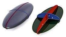
The moment of inertia matrix in body-frame coordinates is a quadratic form that defines a surface in the body called Poinsot's ellipsoid.[28] Let [Λ] be the inertia matrix relative to the centre of mass aligned with the principal axes, then the surface
![\mathbf {x} ^{T}[\Lambda ]\mathbf {x} =1,](../I/m/8e9232e5025da46414de65b1a7e034a1d9e0e7f7.svg)
or

defines an ellipsoid in the body frame. Write this equation in the form,

to see that the semi-principal diameters of this ellipsoid are given by

Let a point x on this ellipsoid be defined in terms of its magnitude and direction, x=|x|n, where n is a unit vector. Then the relationship presented above, between the inertia matrix and the scalar moment of inertia In around an axis in the direction n, yields
![\mathbf {x} ^{T}[\Lambda ]\mathbf {x} =|\mathbf {x} |^{2}\mathbf {n} ^{T}[\Lambda ]\mathbf {n} =|\mathbf {x} |^{2}I_{n}=1.](../I/m/83673548d96e78fea4fd89c7c6e11946e3c077e7.svg)
Thus, the magnitude of a point x in the direction n on the inertia ellipsoid is

See also
- Central moment
- Instant centre of rotation
- List of moments of inertia
- Rotational energy
- Stretch rule
- Tire balance
References
- 1 2 Mach, Ernst (1919). The Science of Mechanics. pp. 173–187. Retrieved November 21, 2014.
- ↑ Euler, Leonhard (1765). Theoria motus corporum solidorum seu rigidorum: Ex primis nostrae cognitionis principiis stabilita et ad omnes motus, qui in huiusmodi corpora cadere possunt, accommodata [The theory of motion of solid or rigid bodies: established from first principles of our knowledge and appropriate for all motions which can occur in such bodies] (in Latin). Rostock and Greifswald (Germany): A. F. Röse. p. 166. ISBN 978-1-4297-4281-8. From page 166: "Definitio 7. 422. Momentum inertiae corporis respectu eujuspiam axis est summa omnium productorum, quae oriuntur, si singula corporis elementa per quadrata distantiarum suarum ab axe multiplicentur." (Definition 7. 422. A body's moment of inertia with respect to any axis is the sum of all of the products, which arise, if the individual elements of the body are multiplied by the square of their distances from the axis.)
- 1 2 3 4 5 6 Marion, JB; Thornton, ST (1995). Classical dynamics of particles & systems (4th ed.). Thomson. ISBN 0-03-097302-3.
- 1 2 Symon, KR (1971). Mechanics (3rd ed.). Addison-Wesley. ISBN 0-201-07392-7.
- 1 2 Tenenbaum, RA (2004). Fundamentals of Applied Dynamics. Springer. ISBN 0-387-00887-X.
- 1 2 3 4 5 6 7 8 9 Kane, T. R.; Levinson, D. A. (1985). Dynamics, Theory and Applications. New York: McGraw-Hill.
- 1 2 Winn, Will (2010). Introduction to Understandable Physics: Volume I - Mechanics. AuthorHouse. p. 10.10. ISBN 1449063330.
- 1 2 Fullerton, Dan (2011). Honors Physics Essentials. Silly Beagle Productions. pp. 142–143. ISBN 0983563330.
- ↑ Wolfram, Stephen (2014). "Spinning Ice Skater". Wolfram Demonstrations Project. Mathematica, Inc. Retrieved September 30, 2014.
- ↑ Hokin, Samuel (2014). "Figure Skating Spins". The Physics of Everyday Stuff. Retrieved September 30, 2014.
- ↑ Breithaupt, Jim (2000). New Understanding Physics for Advanced Level. Nelson Thomas. p. 64. ISBN 0748743146.
- ↑ Crowell, Benjamin (2003). Conservation Laws. Light and Matter. p. 107. ISBN 0970467028.
- ↑ Tipler, Paul A. (1999). Physics for Scientists and Engineers, Vol. 1: Mechanics, Oscillations and Waves, Thermodynamics. Macmillan. p. 304. ISBN 1572594918.
- 1 2 3 4 5 Paul, Burton (June 1979). Kinematics and Dynamics of Planar Machinery. Prentice Hall. ISBN 978-0135160626.
- ↑ Walker, David Halliday, Robert Resnick, Jearl (2005). Fundamentals of physics (7th ed.). Hoboken, NJ: Wiley. ISBN 9780471216438.
- ↑ French, A.P. (1971). Vibrations and waves. Boca Raton, FL: CRC Press. ISBN 9780748744473.
- 1 2 3 4 5 6 Uicker, John J.; Pennock, Gordon R.; Shigley, Joseph E. (2010). Theory of Machines and Mechanisms (4th ed.). Oxford University Press. ISBN 978-0195371239.
- 1 2 3 4 5 6 7 8 9 10 Ferdinand P. Beer; E. Russell Johnston; Jr., Phillip J. Cornwell (2010). Vector mechanics for engineers: Dynamics (9th ed.). Boston: McGraw-Hill. ISBN 978-0077295493.
- ↑ H. Williams, Measuring the inertia tensor, presented at the IMA Mathematics 2007 Conference.
- ↑ Gracey, William, The experimental determination of the moments of inertia of airplanes by a simplified compound-pendulum method, NACA Technical Note No. 1629, 1948
- ↑ In that situation this moment of inertia only describes how a torque applied along that axis causes a rotation about that axis. But, torques not aligned along a principal axis will also cause rotations about other axes.
- ↑ Walter D. Pilkey, Analysis and Design of Elastic Beams: Computational Methods, John Wiley, 2002.
- 1 2 3 Goldstein, H. (1980). Classical Mechanics (2nd ed.). Addison-Wesley. ISBN 0-201-02918-9.
- ↑ L. D. Landau and E. M. Lifshitz, Mechanics, Vol 1. 2nd Ed., Pergamon Press, 1969.
- ↑ L. W. Tsai, Robot Analysis: The mechanics of serial and parallel manipulators, John-Wiley, NY, 1999.
- ↑ Sylvester, J J (1852). "A demonstration of the theorem that every homogeneous quadratic polynomial is reducible by real orthogonal substitutions to the form of a sum of positive and negative squares" (PDF). Philosophical Magazine (Ser. 4). 4 (23): 138–142. doi:10.1080/14786445208647087. Retrieved June 27, 2008.
- ↑ Norman, C.W. (1986). Undergraduate algebra. Oxford University Press. pp. 360–361. ISBN 0-19-853248-2.
- ↑ Mason, Matthew T. (2001). Mechanics of Robotics Manipulation. MIT Press. ISBN 978-0-262-13396-8. Retrieved November 21, 2014.
External links
| Wikimedia Commons has media related to Moments of inertia. |
- Angular momentum and rigid-body rotation in two and three dimensions
- Lecture notes on rigid-body rotation and moments of inertia
- The moment of inertia tensor
- An introductory lesson on moment of inertia: keeping a vertical pole not falling down (Java simulation)
- Tutorial on finding moments of inertia, with problems and solutions on various basic shapes
- Notes on mechanics of manipulation: the angular inertia tensor