Electrical wiring
| Part of a series on |
| Electrical wiring |
|---|
| Regulation of electrical installations |
| Wiring methods |
| Circuit breakers and devices |
| Power engineering |
| Wiring by region or country |

Building wiring is the electrical wiring and associated devices such as switches, meters and light fittings used in buildings or other structures. Electrical wiring uses insulated conductors.
Wires and cables are rated by the circuit voltage, temperature and environmental conditions (moisture, sunlight, oil, chemicals) in which they can be used, and their maximum current. Wiring safety codes vary by country, and the International Electrotechnical Commission (IEC) is attempting to standardise wiring amongst member countries. Colour codes are used to distinguish line, neutral and earth (ground) wires.
Wiring safety codes
Wiring safety codes are intended to protect people and property from electrical shock and fire hazards. Regulations may be established by city, county, provincial/state or national legislation, usually by adopting a model code (with or without local amendments) produced by a technical standards-setting organisation, or by a national standard electrical code.
First Electrical codes arose in the 1880s with the commercial introduction of electrical power. Many conflicting standards existed for the selection of wire sizes and other design rules for electrical installations.
The first electrical codes in the United States originated in New York in 1881 to regulate installations of electric lighting. Since 1897 the US National Fire Protection Association, a private non-profit association formed by insurance companies, has published the National Electrical Code (NEC). States, counties or cities often include the NEC in their local building codes by reference along with local differences. The NEC is modified every three years. It is a consensus code considering suggestions from interested parties. The proposals are studied by committees of engineers, tradesmen, manufacturer representatives, fire fighters and other invitees.
Since 1927, the Canadian Standards Association (CSA) has produced the Canadian Safety Standard for Electrical Installations, which is the basis for provincial electrical codes. The CSA also produces the Canadian Electrical Code, the 2006 edition of which references IEC 60364 (Electrical Installations for Buildings) and states that the code addresses the fundamental principles of electrical protection in Section 131. The Canadian code reprints Chapter 13 of IEC 60364, but there are no numerical criteria listed in that chapter to assess the adequacy of any electrical installation.
Although the US and Canadian national standards deal with the same physical phenomena and broadly similar objectives, they differ occasionally in technical detail. As part of the North American Free Trade Agreement (NAFTA) program, US and Canadian standards are slowly converging toward each other, in a process known as harmonisation.
In Germany, DKE (the German Commission for Electrical, Electronic and Information Technologies of DIN and VDE) is the organisation responsible for the promulgation of electrical standards and safety specifications. DIN VDE 0100 is the German wiring regulations document harmonised with IEC 60364.
In the United Kingdom, wiring installations are regulated by the Institution of Engineering and Technology Requirements for Electrical Installations: IEE Wiring Regulations, BS 7671: 2008, which are harmonised with IEC 60364. The 17th edition (issued in January 2008) includes new sections for microgeneration and solar photovoltaic systems. The first edition was published in 1882.
In Australia and New Zealand, the AS/NZS 3000 standard, commonly known as the "wiring rules", specifies requirements for the selection and installation of electrical equipment, and the design and testing of such installations. The standard is mandatory in both New Zealand and Australia; therefore, all electrical work covered by the standard must comply.
In European countries, an attempt has been made to harmonise national wiring standards in an IEC standard, IEC 60364 Electrical Installations for Buildings. Hence national standards follow an identical system of sections and chapters. However, this standard is not written in such language that it can readily be adopted as a national wiring code. Neither is it designed for field use by electrical tradesmen and inspectors for testing compliance with national wiring standards. By contrast, national codes, such as the NEC or CSA C22.1, generally exemplify the common objectives of IEC 60364, but provide specific rules in a form that allows for guidance of those installing and inspecting electrical systems.
The international standard wire sizes are given in the IEC 60228 standard of the International Electrotechnical Commission. In North America, the American Wire Gauge standard for wire sizes is used.
Colour code
To enable wires to be easily and safely identified, all common wiring safety codes mandate a colour scheme for the insulation on power conductors. In a typical electrical code, some colour-coding is mandatory, while some may be optional. Many local rules and exceptions exist per country, state or region.[1] Older installations vary in colour codes, and colours may fade with insulation exposure to heat, light and ageing.
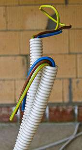
As of March 2011, the European Committee for Electrotechnical Standardization (CENELEC) requires the use of green/yellow colour cables as protective conductors, blue as neutral conductors and brown as single-phase conductors.[2] The United States National Electrical Code requires a green or green/yellow protective conductor, a white or grey neutral, and a black single phase.[3]
The United Kingdom requires the use of wire covered with green insulation, to be marked with a prominent yellow stripe, for safe earthing (grounding) connections.[4] This growing international standard was adopted for its distinctive appearance, to reduce the likelihood of dangerous confusion of safety earthing (grounding) wires with other electrical functions, especially by persons affected by red-green colour blindness.
In the UK, phases could be identified as being live by using coloured indicator lights: red, yellow and blue. The new cable colours of brown, black and grey do not lend themselves to coloured indicators. For this reason, three-phase control panels will often use indicator lights of the old colours.[5]
| Flexible cable (e.g., extension, power, and lamp cords) | |||
|---|---|---|---|
| Region or country | Phases | Neutral | Protective earth/ground |
| Argentina, Australia, European Union, South Africa (IEC 60446) | | | |
| Australia, New Zealand (AS/NZS 3000:2007 3.8.3) | | | |
| Brazil | | | |
| United States, Canada | metallic brass | metallic silver | , green/yellow striped |
| Fixed cable (e.g., in-, on-, or behind-the-wall cables) | |||
| Region or country | Phases | Neutral | Protective earth/ground |
| Argentina; China; European Union (IEC 60446) from April 2004; the United Kingdom from 31 March 2004 (BS 7671); Hong Kong from July 2007; Singapore from March 2009; Russia since 2009 (GOST R 50462); Ukraine, Belarus, Kazakhstan | | | |
| India, Pakistan; United Kingdom, prior to 31 March 2004 (BS 7671); Hong Kong, prior to 2009; Malaysia and Singapore, prior to February 2011 | | |
|
| Australia, New Zealand (AS/NZS 3000:2007 3.8.1, table 3.4) |
|
| |
| Brazil | | | |
| South Africa |
|
| |
| United States[lower-alpha 5] | metallic brass | metallic silver | |
| Canada[6][lower-alpha 5] | |
|
|
| |
| ||
Boxes (e.g., translucent purple) denote markings on wiring terminals.
| |||
Wiring methods
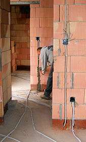
Materials for wiring interior electrical systems in buildings vary depending on:
- Intended use and amount of power demand on the circuit
- Type of occupancy and size of the building
- National and local regulations
- Environment in which the wiring must operate.
Wiring systems in a single family home or duplex, for example, are simple, with relatively low power requirements, infrequent changes to the building structure and layout, usually with dry, moderate temperature and non-corrosive environmental conditions. In a light commercial environment, more frequent wiring changes can be expected, large apparatus may be installed and special conditions of heat or moisture may apply. Heavy industries have more demanding wiring requirements, such as very large currents and higher voltages, frequent changes of equipment layout, corrosive, or wet or explosive atmospheres. In facilities that handle flammable gases or liquids, special rules may govern the installation and wiring of electrical equipment in hazardous areas.
Wires and cables are rated by the circuit voltage, temperature rating and environmental conditions (moisture, sunlight, oil, chemicals) in which they can be used. A wire or cable has a voltage (to neutral) rating and a maximum conductor surface temperature rating. The amount of current a cable or wire can safely carry depends on the installation conditions.
Early wiring methods
The first interior power wiring systems used conductors that were bare or covered with cloth, which were secured by staples to the framing of the building or on running boards. Where conductors went through walls, they were protected with cloth tape. Splices were done similarly to telegraph connections, and soldered for security. Underground conductors were insulated with wrappings of cloth tape soaked in pitch, and laid in wooden troughs which were then buried. Such wiring systems were unsatisfactory because of the danger of electrocution and fire, plus the high labour cost for such installations.
Knob and tube
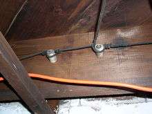
The earliest standardised method of wiring in buildings, in common use in North America from about 1880 to the 1930s, was knob and tube (K&T) wiring: single conductors were run through cavities between the structural members in walls and ceilings, with ceramic tubes forming protective channels through joists and ceramic knobs attached to the structural members to provide air between the wire and the lumber and to support the wires. Since air was free to circulate over the wires, smaller conductors could be used than required in cables. By arranging wires on opposite sides of building structural members, some protection was afforded against short-circuits that can be caused by driving a nail into both conductors simultaneously.
By the 1940s, the labour cost of installing two conductors rather than one cable resulted in a decline in new knob-and-tube installations. However, the US code still allows new K&T wiring installations in special situations (some rural and industrial applications).
Metal-sheathed wires
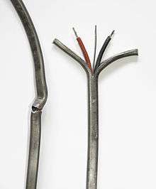
In the United Kingdom, an early form of insulated cable,[7] introduced in 1896, consisted of two impregnated-paper-insulated conductors in an overall lead sheath. Joints were soldered, and special fittings were used for lamp holders and switches. These cables were similar to underground telegraph and telephone cables of the time. Paper-insulated cables proved unsuitable for interior wiring installations because very careful workmanship was required on the lead sheaths to ensure moisture did not affect the insulation.
A system later invented in the UK in 1908 employed vulcanised-rubber insulated wire enclosed in a strip metal sheath. The metal sheath was bonded to each metal wiring device to ensure earthing continuity.
A system developed in Germany called "Kuhlo wire" used one, two, or three rubber-insulated wires in a brass or lead-coated iron sheet tube, with a crimped seam. The enclosure could also be used as a return conductor. Kuhlo wire could be run exposed on surfaces and painted, or embedded in plaster. Special outlet and junction boxes were made for lamps and switches, made either of porcelain or sheet steel. The crimped seam was not considered as watertight as the Stannos wire used in England, which had a soldered sheath.[8]
A somewhat similar system called "concentric wiring" was introduced in the United States around 1905. In this system, an insulated electrical wire was wrapped with copper tape which was then soldered, forming the grounded (return) conductor of the wiring system. The bare metal sheath, at earth potential, was considered safe to touch. While companies such as General Electric manufactured fittings for the system and a few buildings were wired with it, it was never adopted into the US National Electrical Code. Drawbacks of the system were that special fittings were required, and that any defect in the connection of the sheath would result in the sheath becoming energised.[9]
Other historical wiring methods
Other methods of securing wiring that are now obsolete include:
- Re-use of existing gas pipes when converting gas light installations to electric lighting. Insulated conductors were pulled through the pipes that had formerly supplied the gas lamps. Although used occasionally, this method risked insulation damage from sharp edges inside the pipe at each joint.
- Wood mouldings with grooves cut for single conductor wires, covered by a wooden cap strip. These were prohibited in North American electrical codes by 1928. Wooden moulding was also used to some degree in England, but was never permitted by German and Austrian rules.[10]
- A system of flexible twin cords supported by glass or porcelain buttons was used near the turn of the 20th century in Europe, but was soon replaced by other methods.[11]
- During the first years of the 20th century, various patented forms of wiring system such as Bergman and Peschel tubing were used to protect wiring; these used very thin fiber tubes, or metal tubes which were also used as return conductors.[12]
- In Austria, wires were concealed by embedding a rubber tube in a groove in the wall, plastering over it, then removing the tube and pulling wires through the cavity.[13]
Metal moulding systems, with a flattened oval section consisting of a base strip and a snap-on cap channel, were more costly than open wiring or wooden moulding, but could be easily run on wall surfaces. Similar surface mounted raceway wiring systems are still available today.
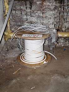
Cables
Armoured cables with two rubber-insulated conductors in a flexible metal sheath were used as early as 1906, and were considered at the time a better method than open knob-and-tube wiring, although much more expensive.
The first rubber-insulated cables for building wiring were introduced in 1922 with US patent 1458803, Burley, Harry & Rooney, Henry, "Insulated electric wire", issued 1923-06-12, assigned to Boston Insulated Wire And Cable. These were two or more solid copper electrical wires with rubber insulation, plus woven cotton cloth over each conductor for protection of the insulation, with an overall woven jacket, usually impregnated with tar as a protection from moisture. Waxed paper was used as a filler and separator.
Over time, rubber-insulated cables become brittle because of exposure to atmospheric oxygen, so they must be handled with care and are usually replaced during renovations. When switches, socket outlets or light fixtures are replaced, the mere act of tightening connections may cause hardened insulation to flake off the conductors. Rubber insulation further inside the cable often is in better condition than the insulation exposed at connections, due to reduced exposure to oxygen.
The sulphur in vulcanised rubber insulation attacked bare copper wire so the conductors were tinned to prevent this. The conductors reverted to being bare when rubber ceased to be used.

About 1950, PVC insulation and jackets were introduced, especially for residential wiring. About the same time, single conductors with a thinner PVC insulation and a thin nylon jacket (e.g. US Type THN, THHN, etc.) became common.
The simplest form of cable has two insulated conductors twisted together to form a unit. Such un-jacketed cables with two (or more) conductors are used only for extra low voltage signal and control applications such as doorbell wiring.
In North American practice, an overhead cable from a transformer on a power pole to a residential electrical service usually consists of three twisted (triplexed) conductors, with one being a bare protective neutral/earth/ground conductor (which may be made of copper), with the other two being the insulated conductors for both of the two 180 degree out of phase 120 V line voltages normally supplied.[14] However, the earthed/grounded conductor is often a catenary cable (made of steel wire), which is used to support the insulated Line conductors. For additional safety, the ground conductor may be formed into a stranded co-axial layer completely surrounding the phase/line conductors, so that the outermost conductor is grounded.
Copper conductors
Electrical devices often contain copper conductors because of their multiple beneficial properties, including their high electrical conductivity, tensile strength, ductility, creep resistance, corrosion resistance, thermal conductivity, coefficient of thermal expansion, solderability, resistance to electrical overloads, compatibility with electrical insulators and ease of installation.
Despite competition from other materials, copper remains the preferred electrical conductor in nearly all categories of electrical wiring.[15][16] For example, copper is used to conduct electricity in high, medium and low voltage power networks, including power generation, power transmission, power distribution, telecommunications, electronics circuitry, data processing, instrumentation, appliances, entertainment systems, motors, transformers, heavy industrial machinery and countless other types of electrical equipment.[17]
Aluminium conductors
Aluminium wire was common in North American residential wiring from the late 1960s to mid-1970s due to the rising cost of copper. Because of its greater resistivity, aluminium wiring requires larger conductors than copper. For instance, instead of 14 AWG (American wire gauge) copper wire, aluminium wiring would need to be 12 AWG on a typical 15 ampere lighting circuit, though local building codes vary.
Solid aluminum conductors were originally made in the 1960's from a utility grade aluminum alloy that had undesirable properties for a building wire, and were indiscriminately used with wiring devices intended for copper conductors and often poorly installed.[18][19] These practices were found to cause defective connections and potential fire hazards. In the early-1970's new aluminum wire made from one of several special alloys was introduced, and all devices — breakers, switches, receptacles, splice connectors, wire nuts, etc. — were specially designed for the purpose. These newer aluminum wires and special designs address problems with junctions between dissimilar metals, oxidation on metal surfaces and mechanical effects that occur as different metals expand at different rates with increases in temperature.
Unlike copper, aluminium has a tendency to creep or cold-flow under pressure, so older plain steel screw clamped connections could become loose over time. This was be mitigated by using proper installation practices with newer electrical devices (e.g. proper torque on special termination screws), special spring-loaded connectors that apply constant pressure, applying high pressure cold joints in splices and termination fittings, or using a bolted mechanical type clamp wire connector and tightening it to a specified torque.
Also unlike copper, aluminium forms an insulating oxide layer on the surface. This is sometimes addressed by coating aluminium conductors with an antioxidant paste (containing zinc dust in a low-residue polybutene base[20]) at joints, or by applying a mechanical termination designed to break through the oxide layer during installation.
Because of improper design and installation, some junctions to wiring devices would overheat under heavy current load, and cause fires. Revised standards for wire materials and wiring devices (such as the CO/ALR "copper-aluminium-revised" designation) were developed to reduce these problems. While larger sizes are still used to feed power to electrical panels and large devices, aluminium wiring for residential use has acquired a poor reputation and has fallen out of favour.
Aluminium conductors are still used for bulk power distribution and large feeder circuits, because they cost less than copper wiring, and weigh less, especially in the large sizes needed for heavy current loads. Aluminium conductors must be installed with compatible connectors and special care must be taken to ensure the contact surface does not oxidise.
Modern wiring materials
Modern non-metallic sheathed cables, such as (US and Canadian) Types NMB and NMC, consist of two to four wires covered with thermoplastic insulation, plus a bare wire for grounding (bonding), surrounded by a flexible plastic jacket. Some versions wrap the individual conductors in paper before the plastic jacket is applied.
Special versions of non-metallic sheathed cables, such as US Type UF, are designed for direct underground burial (often with separate mechanical protection) or exterior use where exposure to ultraviolet radiation (UV) is a possibility. These cables differ in having a moisture-resistant construction, lacking paper or other absorbent fillers, and being formulated for UV resistance.
Rubber-like synthetic polymer insulation is used in industrial cables and power cables installed underground because of its superior moisture resistance.
Insulated cables are rated by their allowable operating voltage and their maximum operating temperature at the conductor surface. A cable may carry multiple usage ratings for applications, for example, one rating for dry installations and another when exposed to moisture or oil.
Generally, single conductor building wire in small sizes is solid wire, since the wiring is not required to be very flexible. Building wire conductors larger than 10 AWG (or about 6 mm²) are stranded for flexibility during installation, but are not sufficiently pliable to use as appliance cord.
Cables for industrial, commercial and apartment buildings may contain many insulated conductors in an overall jacket, with helical tape steel or aluminium armour, or steel wire armour, and perhaps as well an overall PVC or lead jacket for protection from moisture and physical damage. Cables intended for very flexible service or in marine applications may be protected by woven bronze wires. Power or communications cables (e.g., computer networking) that are routed in or through air-handling spaces (plenums) of office buildings are required under the model building code to be either encased in metal conduit, or rated for low flame and smoke production.

For some industrial uses in steel mills and similar hot environments, no organic material gives satisfactory service. Cables insulated with compressed mica flakes are sometimes used. Another form of high-temperature cable is a mineral insulated cable, with individual conductors placed within a copper tube and the space filled with magnesium oxide powder. The whole assembly is drawn down to smaller sizes, thereby compressing the powder. Such cables have a certified fire resistance rating and are more costly than non-fire rated cable. They have little flexibility and behave more like rigid conduit rather than flexible cables.
There are different factors that determine how much current a cable is permitted to carry. Because multiple conductors bundled in a cable cannot dissipate heat as easily as single insulated conductors, those circuits are always rated at a lower "ampacity". Tables in electrical safety codes give the maximum allowable current based on size of conductor, voltage potential, insulation type and thickness, and the temperature rating of the cable itself. The allowable current will also be different for wet or dry locations, for hot (attic) or cool (underground) locations. In a run of cable through several areas, the part with the lowest rating becomes the rating of the overall run.
Cables usually are secured with special fittings where they enter electrical apparatus; this may be a simple screw clamp for jacketed cables in a dry location, or a polymer-gasketed cable connector that mechanically engages the armour of an armoured cable and provides a water-resistant connection. Special cable fittings may be applied to prevent explosive gases from flowing in the interior of jacketed cables, where the cable passes through areas where flammable gases are present. To prevent loosening of the connections of individual conductors of a cable, cables must be supported near their entrance to devices and at regular intervals along their runs. In tall buildings, special designs are required to support the conductors of vertical runs of cable. Generally, only one cable per fitting is permitted, unless the fitting is rated or listed for multiple cables.
Special cable constructions and termination techniques are required for cables installed in ocean-going vessels. Such assemblies are subjected to environmental and mechanical extremes. Therefore, in addition to electrical and fire safety concerns, such cables may also be required to be pressure-resistant where they penetrate a vessel's bulkheads. They must also resist corrosion caused by salt water or salt spray, which is accomplished through the use of thicker, specially constructed jackets, and by tinning the individual wire stands.
Raceways
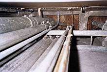
Insulated wires may be run in one of several forms of a raceway between electrical devices. This may be a specialised bendable pipe, called a conduit, or one of several varieties of metal (rigid steel or aluminium) or non-metallic (PVC or HDPE) tubing. Rectangular cross-section metal or PVC wire troughs (North America) or trunking (UK) may be used if many circuits are required. Wires run underground may be run in plastic tubing encased in concrete, but metal elbows may be used in severe pulls. Wiring in exposed areas, for example factory floors, may be run in cable trays or rectangular raceways having lids.
Where wiring, or raceways that hold the wiring, must traverse fire-resistance rated walls and floors, the openings are required by local building codes to be firestopped. In cases where safety-critical wiring must be kept operational during an accidental fire, fireproofing must be applied to maintain circuit integrity in a manner to comply with a product's certification listing. The nature and thickness of any passive fire protection materials used in conjunction with wiring and raceways has a quantifiable impact upon the ampacity derating, because the thermal insulation properties needed for fire resistance also inhibit air cooling of power conductors.

Cable trays are used in industrial areas where many insulated cables are run together. Individual cables can exit the tray at any point, simplifying the wiring installation and reducing the labour cost for installing new cables. Power cables may have fittings in the tray to maintain clearance between the conductors, but small control wiring is often installed without any intentional spacing between cables.
Note that cable trays are very common in two-way radio sites where they are used for antenna cables, some of which can be 3 1/8 inches (8 cm) or even larger. Local codes may preclude mixing power cables with antenna cables in the same tray.
Since wires run in conduits or underground cannot dissipate heat as easily as in open air, and since adjacent circuits contribute induced currents, wiring regulations give rules to establish the current capacity (ampacity).
Special sealed fittings are used for wiring routed through potentially explosive atmospheres.
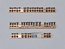
Bus bars, bus duct, cable bus

For very high currents in electrical apparatus, and for high currents distributed through a building, bus bars can be used. (The term "bus" is a contraction of the Latin omnibus – meaning "for all".) Each live conductor of such a system is a rigid piece of copper or aluminium, usually in flat bars (but sometimes as tubing or other shapes). Open bus bars are never used in publicly accessible areas, although they are used in manufacturing plants and power company switch yards to gain the benefit of air cooling. A variation is to use heavy cables, especially where it is desirable to transpose or "roll" phases.
In industrial applications, conductor bars are often pre-assembled with insulators in grounded enclosures. This assembly, known as bus duct or busway, can be used for connections to large switchgear or for bringing the main power feed into a building. A form of bus duct known as "plug-in bus" is used to distribute power down the length of a building; it is constructed to allow tap-off switches or motor controllers to be installed at designated places along the bus. The big advantage of this scheme is the ability to remove or add a branch circuit without removing voltage from the whole duct.
Bus ducts may have all phase conductors in the same enclosure (non-isolated bus), or may have each conductor separated by a grounded barrier from the adjacent phases (segregated bus). For conducting large currents between devices, a cable bus is used.
For very large currents in generating stations or substations, where it is difficult to provide circuit protection, an isolated-phase bus is used. Each phase of the circuit is run in a separate grounded metal enclosure. The only fault possible is a phase-to-ground fault, since the enclosures are separated. This type of bus can be rated up to 50,000 amperes and up to hundreds of kilovolts (during normal service, not just for faults), but is not used for building wiring in the conventional sense.
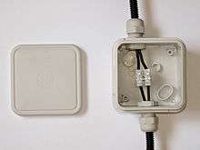
Electrical panels

Electrical panels are easily accessible junction boxes used to reroute and switch electrical services. The term is often used to refer to circuit breaker panels or fuseboxes. Local codes can specify physical clearance around the panels.
Degradation by pests
Rasberry crazy ants have been known to consume the insides of electrical wiring installations, preferring DC over AC currents. This behaviour is not well understood by scientists.[21]
Squirrels, rats and other rodents may gnaw on unprotected wiring, causing fire and shock hazards.[22][23] This is especially true of PVC-insulated telephone and computer network cables. Several techniques have been developed to deter these pests, including insulation loaded with pepper dust.
See also
- 10603 – a frequently used MIL-SPEC compliant wire
- Cable
- Bus Ducts
- Cable Entry System
- Cable gland
- Cable management
- Cable tray
- Domestic AC power plugs and sockets
- Electrical conduit
- Electrical room
- Electrical wiring in North America
- Electrical wiring in the United Kingdom
- Electricity distribution
- Grounding
- Home wiring
- Industrial and multiphase power plugs and sockets
- MIL-DTL-13486 – MIL-SPEC compliant wire
- Neutral wire
- OFHC
- Portable cord
- Restriction of Hazardous Substances Directive (RoHS)
- Single-phase electric power
- Structured cabling
- Three-phase electric power
References
- ↑ "National Electrical Code". National Electrical Manufacturers Association. Retrieved 4 January 2016.
- ↑ "New Cable Colour Code for Electrical Installations". Energy Market Authority. Retrieved 4 January 2016.
- ↑ "Color Coding Chart". Conwire. Retrieved 4 January 2016.
- ↑ Noel Williams, Jeffrey S. Sargen. "NEC Q and A: Questions and Answers on the National Electrical Code". p. 117. Retrieved 4 January 2016.
- ↑ "Wiring Color Codes Infographic". All About Circuits. Retrieved 4 January 2016.
- ↑ C22.1-15—Canadian Electrical Code, Part I: Safety Standard for Electrical Installations (23rd ed.). Canadian Standards Association. 2015. Rules 4-038, 24-208(c). ISBN 978-1-77139-718-6.
- ↑ Robert M. Black, The History of Electric Wires and Cable, Peter Pergrinus Ltd. London, 1983 ISBN 0-86341-001-4, pp. 155–158
- ↑ Croft
- ↑ Schneider, Norman H., Wiring houses for the electric light; together with special references to low voltage battery systems, Spon and Chamberlain, New York 1916, pp. 93–98
- ↑ Croft, p. 142
- ↑ Croft, p. 143
- ↑ Croft, p. 136
- ↑ Croft, p. 137
- ↑ "Generating Power to Your House - How Power Grids Work - HowStuffWorks". HowStuffWorks. Retrieved 21 February 2016.
- ↑ Pops, Horace (June 2008). "Processing of wire from antiquity to the future". Wire Journal International: 58–66.
- ↑ The Metallurgy of Copper Wire. litz-wire.com
- ↑ Joseph, Günter, 1999, Copper: Its Trade, Manufacture, Use, and Environmental Status, Kundig, Konrad J.A. (ed.), ASM International, ISBN 0871706563, pp. 141–192, 331–375
- ↑ "The Evolution of Aluminum Conductors Used for Building Wire and Cable" (PDF). NEMA. 2012.
- ↑ "Aluminum Building Wire Installation & Terminations" (PDF). IAEI News (January/February 2006).
- ↑ "Ideal Noalox Antioxidant Material Safety Data Sheet" (PDF).
- ↑ Andrew R Hickey (15 May 2008). "'Crazy' Ant Invasion Frying Computer Equipment".
- ↑ "Guide to Safe Removal". Squirrels in the Attic. Retrieved 19 April 2012.
- ↑ University of Illinois Extension. "Tree Squirrels > Damage Prevention and Control Measures". Living with Wildlife in Illinois. University of Illinois Board of Trustees. Retrieved 12 March 2013.
Bibliography
- Croft, Terrel (1915) Wiring of Finished Buildings, McGraw Hill, New York.
Further reading
- National Electrical Code — Basis of most US electrical codes. Choose NFPA 70 (general purpose) or NFPA 70A (one and two family dwellings). Free registration required.
- National Electrical Code 2011 (2011 ed.), Quincy MA: National Fire Protection Association, 2010. — periodically re-issued every 3 years
- NEMA comparison of IEC 60364 with the US NEC
- Cauldwell, Rex (2002). Wiring a House (For Pros By Pros). Newtown, CT, USA: Taunton Press. ISBN 1-56158-527-0.
- Hirst, E. Electric Utilities and Energy
- Litchfield, Michael; Michael McAlister (2008). Taunton's wiring complete : expert advice from start to finish (Revised ed.). Newtown, CT: Taunton Press. ISBN 978-1-60085-256-5.
External links
| Wikimedia Commons has media related to Electrical wiring. |
- Electrical wiring FAQ — oriented to US/Canadian practice