Integrated Truss Structure
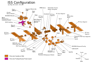
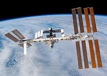
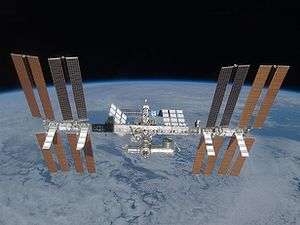
The Integrated Truss Structure (ITS) of the International Space Station (ISS) consists of a linearly arranged sequence of connected trusses on which various unpressurized components are mounted, such as logistics carriers, radiators, solar arrays, and other equipment. It supplies the ISS with a bus architecture.
Truss components
All truss components were named after their planned end-positions: Z for zenith, S for starboard and P for port, with the number indicating the sequential position. The S0 truss might be considered a misnomer, as it is mounted centrally on the zenith position of Destiny and is neither starboard nor port side.
Z1 truss
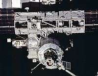
The first truss piece, the Z1 truss, launched aboard STS-92 in October 2000. It contains the control moment gyroscope (CMG) assemblies, electrical wiring, communications equipment, and two plasma contactors designed to neutralize the static electrical charge of the space station.
Another objective of the Z1 truss was to serve as a temporary mounting position for the "P6 truss and solar array" until its relocation to the end of the P5 truss during STS-120. Though not a part of the main truss, the Z1 truss was the first permanent lattice-work structure for the ISS, very much like a girder, setting the stage for the future addition of the station's major trusses or backbones.

While the bulk of the Z1 truss is unpressurized, it features a Common Berthing Mechanism (CBM) port that connects its nadir to the zenith port of Unity and contains a small pressurized dome that allowed astronauts to connect electrical ground straps between Unity and the truss without an EVA.[1][2] In addition, the dome inside the CBM of Z1 can be used as storage space.[3]
The Z1 truss also features a forward-facing Manual Berthing Mechanism (MBM) ring.[4] This MBM is not a port and is not pressurized or electrically powered, but it can be operated with a handheld tool to berth any passive CBM to it.[5] The Z1 truss's MBM was used only once, to temporarily hold PMA-2, while the Destiny lab was being berthed onto the Unity node during STS-98. Since the installation of the nearby S0 truss in April 2002, access to the MBM has been blocked.
In October 2007, the P6 was moved to its permanent position next to P5—the Z1 truss is now solely used to house the CMGs, communications equipment and the plasma contactors; Z1 no longer connects other space station elements to Unity (Node 1).
In December 2008, the Ad Astra Rocket Company announced an agreement with NASA to place a flight test version of its VASIMR rocket on the station to take over reboost duties. In 2013, Ad Astra announced specific plans to place the thruster module, named Aurora, on top of the Z1 truss in 2015.[6]
S0 truss
The S0 truss, (also called the Center Integrated Truss Assembly Starboard 0 Truss) forms the center backbone of the Space Station. It was attached on the top of the Destiny Laboratory Module during STS-110 in April 2002. S0 is used to route power to the pressurized station modules and conduct heat away from the modules to the S1 and P1 Trusses. The S0 truss is not docked to the ISS, but is connected with four Module to Truss Structure (MTS) struts.
P1, S1 trusses
The P1 and S1 trusses (also called the Port and Starboard Side Thermal Radiator Trusses) are attached to the S0 truss, and contain carts to transport the Canadarm2 and astronauts to worksites along the space station. They each flow 290 kg (637 lb) of anhydrous ammonia through three heat rejection radiators. The S1 truss was launched on STS-112 in October 2002 and the P1 truss was launched on STS-113 in November 2002. Detailed design, test and construction of the S1 and P1 structures was conducted by McDonnell Douglas (now Boeing) in Huntington Beach, CA. First parts were cut for the structure in 1996, and delivery of the first truss occurred in 1999.
P2, S2 trusses
The P2 and S2 trusses were planned as locations for rocket thrusters in the original design for Space Station Freedom. Since the Russian parts of the ISS also provided that capability, the reboost capability of the Space Station Freedom design was no longer needed at that location. So P2 and S2 were canceled.[7]
P3/P4, S3/S4 truss assemblies
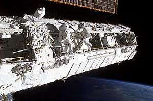
The P3/P4 truss assembly was installed by the Space Shuttle Atlantis STS-115 mission, launched September 9, 2006, and attached to the P1 segment. The P3 and P4 segments together contain a pair of solar arrays, a radiator and a rotary joint that will aim the solar arrays, and connects P3 to P4. Upon its installation, no power was flowing across the rotary joint, so the electricity generated by the P4 solar array wings was only being used on the P4 segment, and not the rest of the station. Then in December 2006 a major electrical rewiring of the station by STS-116 routed this power to the entire grid. The S3/S4 truss assembly—a mirror-image of P3/P4—was installed on June 11, 2007 also by Space Shuttle Atlantis during flight STS-117, mission 13A and mounted to the S1 truss segment.
Major P3 and S3 subsystems include the Segment-to-Segment Attach System (SSAS), Solar Alpha Rotary Joint (SARJ), and Unpressurized Cargo Carrier Attach System (UCCAS). The primary functions of the P3 truss segment are to provide mechanical, power and data interfaces to payloads attached to the two UCCAS platforms; axial indexing for solar tracking, or rotating of the arrays to follow the sun, via the SARJ; movement and work site accommodations for the Mobile Transporter. The P3/S3 primary structure is made of a hexagonal shaped aluminum structure and includes four bulkheads and six longerons.[8] The S3 truss also supports EXPRESS Logistics Carrier locations, first to be launched and installed in the 2009 time frame.
Major subsystems of the P4 and S4 Photovoltaic Modules (PVM) include the two Solar Array Wings (SAW), the Photovoltaic Radiator (PVR), the Alpha Joint Interface Structure (AJIS), and Modified Rocketdyne Truss Attachment System (MRTAS), and Beta Gimbal Assembly (BGA).
P5, S5 trusses
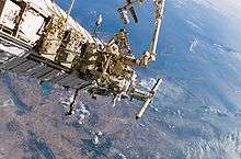
The P5 and S5 trusses are connectors which support the P6 and S6 trusses, respectively. The P3/P4 and S3/S4 truss assemblies' length was limited by the cargo bay capacity of the Space Shuttle, so these small connectors are needed to extend the truss. The P5 truss was installed on December 12, 2006 during the first EVA of mission STS-116. The S5 truss was brought into orbit by mission STS-118 and installed on August 11, 2007.
P6, S6 trusses
The P6 truss was the second truss segment to be added, because it contains a large Solar Array Wing (SAW) that generated essential electricity for the station, prior to activation of the SAW on the P4 truss. It was originally mounted to the Z1 truss and had its SAW extended during STS-97, but the SAW was folded, one half at a time, to make room for the SAWs on the P4 and S4 trusses, during STS-116 and STS-117 respectively. Shuttle mission STS-120 (assembly mission 10A) detached the P6 truss from Z1, remounted it on the P5 truss, redeployed its radiator panels and attempted to redeploy its SAWs. One SAW (2B) was deployed successfully but the second SAW (4B) developed a significant tear that temporarily stopped deployment at around 80%. This was subsequently fixed and the array is now fully deployed. A later assembly mission (the out of sequence STS-119) mounted the S6 truss on the S5 truss, which provided a fourth and final set of solar arrays and radiators.
-

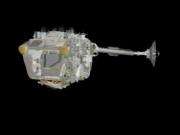
Z1 truss (above) and Unity Module (below) from STS-92 in October 2000
-
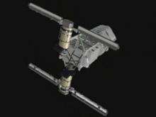
The S0 truss (above) from STS-110 April 17, 2002
-

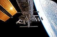
ISS S1 truss element being installed on STS-112 October 10, 2002
-
ISS P1 truss element being installed on STS-113 November 28, 2002
-
The P3/P4 truss assembly being installed during STS-115 September 13, 2006. Astronauts give scale to the image.
-
.jpg)
Space Shuttle Discovery's Canadarm-1 robotic arm hands off the P5 truss section to the International Space Station's Canadarm-2 during shuttle mission STS-116 in December, 2006.
-
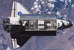
Space Shuttle Endeavour approaches the International Space Station during mission STS-118 with the S5 truss section ready to be installed.
Truss subsystems
Solar arrays
.jpg)
The International Space Station's main source of energy is from three of the four large U.S.-made photovoltaic arrays currently on the station, sometimes referred to as the Solar Array Wings (SAW). The first pair of arrays are attached to the P6 truss segment, which was launched and installed on top of Z1 in late 2000 during STS-97. The P6 segment was relocated to its final position, bolted to the P5 truss segment, in November 2007 during STS-120. The second pair of arrays was launched and installed in September 2006 during STS-115, but they didn't provide electricity until STS-116 in December 2006 when the station got an electrical rewiring. A third pair of arrays was installed during STS-117 in June 2007. A final pair arrived mid March 2009 on STS-119. More solar power was to have been available via the Russian-built Science Power Platform, but it was canceled.[8]
Each of the Solar Array Wings are 34 m (112 ft) long by 12 m (39 ft) wide, and are capable of generating nearly 32.8 kW of DC power.[9] They are split into two photovoltaic blankets, with the deployment mast in between. Each blanket has 16,400 silicon photovoltaic cells, each cell measuring 8 cm x 8 cm, grouped into 82 active panels, each consisting of 200 cells, with 4,100 diodes.[8]
Each pair of blankets is folded like an accordion for compact delivery to space. Once in orbit, the deployment mast between each pair of blankets unfolds the array to its full length. Gimbals, known as the Beta Gimbal Assembly (BGA) are used to rotate the arrays so that they face the Sun to provide maximum power to the International Space Station.
Solar alpha rotary joint
The Alpha joint is the main rotary joint allowing the solar arrays to track the sun; in nominal operation the alpha joint rotates by 360° each orbit (however, see also Night Glider mode). One Solar Alpha Rotary Joint (SARJ) is located between the P3 and P4 truss segments and the other is located between the S3 and S4 truss segments. When in operation, these joints continuously rotate to keep the solar array wings on the outboard truss segments oriented towards the Sun. Each SARJ is 10 feet in diameter, weighs approximately 2,500 pounds and can be rotated continuously using bearing assemblies and a servo control system. On both the port and starboard sides, all of the power flows through the Utility Transfer Assembly (UTA) in the SARJ. Roll ring assemblies allow transmission of data and power across the rotating interface so it never has to unwind. The SARJ was designed, built and tested by Lockheed Martin and its subcontractors.[8]
The Solar Alpha Rotary Joints contain Drive Lock Assemblies which allow the outer segments of the ITS to rotate and track the Sun. A component of the DLA is a pinion which engages with the race ring that serves as a bull gear. There are two race rings and two DLAs in each SARJ providing on-orbit redundancy, however a series of space walks would be required to reposition the DLAs and the Trundle Bearing Assemblies (TBAs) to utilize the alternate race ring. A spare DLA was brought to the ISS on STS-122.[10]
In 2007, a problem was detected in the starboard SARJ and in one of the two beta gimbal assemblies (BGA).[11] Damage had occurred due to excessive and premature wear of a track in the joint mechanism. The SARJ was frozen during problem diagnosis, and in 2008 lubrication was applied to the track to address the issue.
Power conditioning and storage
The sequential shunt unit (SSU) is designed to coarsely regulate the solar power collected during periods of insolation—when the arrays collect power during sun-pointing periods. A sequence of 82 separate strings, or power lines, leads from the solar array to the SSU. Shunting, or controlling, the output of each string regulates the amount of power transferred. The regulated voltage setpoint is controlled by a computer located on the IEA and is normally set to around 140 volts. The SSU has an overvoltage protection feature to maintain the output voltage below 200 V DC maximum for all operating conditions. This power is then passed through the BMRRM to the DCSU located in the IEA. The SSU measures 32” by 20” by 12” and weighs 185 pounds.
The power storage system consists of a battery charge/discharge unit (BCDU) and two nickel–hydrogen battery assemblies.
Each battery assembly consist of 38 lightweight Nickel Hydrogen cells and associated electrical and mechanical equipment. Each battery assembly has a nameplate capacity of 81 Ah and 4 kWh.[12] This power is fed to the ISS via the BCDU and DCSU respectively. The batteries have a design life of 6.5 years and can exceed 38,000 charge/discharge cycles at 35% depth of discharge. Each battery measures 40” by 36” by 18” and weighs 375 pounds.[13]
Mobile Base System
The Mobile Base System(MBS) is a platform for the robotic arms Canadarm2 and Dextre carrying them 108 metres down rails between the S3 and P3 truss.[14] Beyond the rails Canadarm2 can step over the alpha rotary joint and relocate to grapple fixtures on the S6 and P6 truss. During STS-120 Astronaut Scott Parazynski rode the Orbiter Boom Sensor to repair a tear in the 4B solar array.
Truss and solar array assembly sequence
| Element | Flight | Launch date | Length (m) |
Diameter (m) |
Mass (kg) |
|---|---|---|---|---|---|
| Z1 truss | 3A—STS-92 | October 11, 2000 | 4.9 | 4.2 | 8,755 |
| P6 truss—solar array | 4A—STS-97 | November 30, 2000 | 73.2 | 10.7 | 15,824 |
| S0 truss | 8A—STS-110 | April 8, 2002 | 13.4 | 4.6 | 13,971 |
| S1 truss | 9A—STS-112 | October 7, 2002 | 13.7 | 4.6 | 14,124 |
| P1 truss | 11A—STS-113 | November 23, 2002 | 13.7 | 4.6 | 14,003 |
| P3/P4 truss—solar array | 12A—STS-115 | September 9, 2006 | 13.8 | 4.8 | 15,824 |
| P5 truss—spacer | 12A.1—STS-116 | December 9, 2006 | 3.37 | 4.55 | 1,864 |
| S3/S4 truss—solar array | 13A—STS-117 | June 8, 2007 | 73.2 | 10.7 | 15,824 |
| S5 truss—spacer | 13A.1—STS-118 | August 8, 2007 | 3.37 | 4.55 | 1,818 |
| P6 truss—solar array (relocation) | 10A—STS-120 | October 23, 2007 | 73.2 | 10.7 | 15,824 |
| S6 truss—solar array | 15A—STS-119 | March 15, 2009 | 73.2 | 10.7 | 15,824 |

-
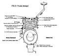
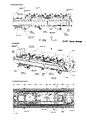
Z1 Truss design
-
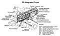
S0 Truss design
-
P1 / S1 Truss design
-

P3/4 / S3/4 Truss design
-

P5 / S5 Truss design
-
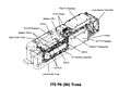
P6 / S6 Truss design
See also
- Science Power Platform—the canceled truss structure of the Russian Orbital Segment
- ISS assembly sequence
- List of manned spaceflights to the ISS
References
- ↑ William Harwood (14 October 2000). "Truss structure to be added to space station today". Spaceflight Now. Retrieved 21 September 2009.
- ↑ "International Space Station Status Briefing, June 13, 2005".
- ↑ "International Space Station Status Briefing, June 13, 2005 – Commander with packed Z1".
- ↑ "NASA STS-92 Press Kit" (PDF) (Press release). 2002-06-02.
- ↑ "Active and Passive with latches and bolts". ISS Interface Mechanisms and their Heritage. 2011-01-01. 20110010964.
- ↑ "High-Tech VASIMR Engine Could Power Superfast Journeys to Mars".
- ↑ "Ask The Mission Team - Question and Answer Session". NASA. Retrieved September 12, 2006.
- 1 2 3 4 "STS-115 Press kit" (PDF). Retrieved September 20, 2006.
- ↑ "Spread Your Wings, It is Time to Fly". NASA. July 26, 2006. Retrieved September 21, 2006.
- ↑ Chris Bergin (November 28, 2007). "STS-122 spacewalkers gain extra protection". NASA SpaceFlight.com. Retrieved 2007-12-01.
- ↑ WILLIAM HARWOOD, "New solar array drive motor successfully tested, January 30, 2008, Spaceflight Now (accessed July 9, 2012)
- ↑ "International Space Station Nickel-Hydrogen Batteries Approached 3-Year On-Orbit Mark". NASA. Retrieved September 14, 2007.
- ↑ "STS-97 Payload: Photovoltaic Array Assembly (PVAA)". NASA. Retrieved September 14, 2007.
- ↑ http://www.asc-csa.gc.ca/eng/iss/mobile-base/backgrounder.asp
External links
| Wikinews has related news: International Space Station's solar panel damaged |
