Centrifugal compressor


Centrifugal compressors, sometimes termed radial compressors, are a sub-class of dynamic axisymmetric work-absorbing turbomachinery.[1]
The idealized compressive dynamic turbo-machine achieves a pressure rise by adding kinetic energy/velocity to a continuous flow of fluid through the rotor or impeller. This kinetic energy is then converted to an increase in potential energy/static pressure by slowing the flow through a diffuser. The pressure rise in impeller is in most cases almost equal to the rise in the diffuser section.
Theory of operation
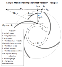
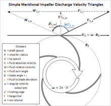
In the case of where flow simply passes through a straight pipe to enter a centrifugal compressor; the flow is straight, uniform and has no vorticity. As illustrated below α1 = 0°. As the flow continues to pass into and through the centrifugal impeller, the impeller forces the flow to spin faster and faster. According to a form of Euler's fluid dynamics equation, known as pump and turbine equation, the energy input to the fluid is proportional to the flow's local spinning velocity multiplied by the local impeller tangential velocity.
In many cases the flow leaving centrifugal impeller is near the speed of sound (340 metres/second). The flow then typically flows through a stationary compressor causing it to decelerate. These stationary compressors are actually static guide vanes where energy transformation takes place. As described in Bernoulli's principle, this reduction in velocity causes the pressure to rise leading to a compressed fluid.[1]
Historical contributions, the pioneers
Over the past 100 years, applied scientists including Stodola (1903, 1927–1945),[2] Pfleiderer (1952),[3] Hawthorne (1964),[4] Shepard (1956),[1] Lakshminarayana (1996),[5] and Japikse (many texts including citations),[6][7][8][9] have educated young engineers in the fundamentals of turbomachinery. These understandings apply to all dynamic, continuous-flow, axisymmetric pumps, fans, blowers, and compressors in axial, mixed-flow and radial/centrifugal configurations.
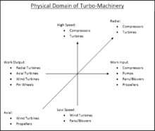
This relationship is the reason advances in turbines and axial compressors often find their way into other turbomachinery including centrifugal compressors. Figures 1.1 and 1.2[10][11] illustrate the domain of turbomachinery with labels showing centrifugal compressors. Improvements in centrifugal compressors have not been achieved through large discoveries. Rather, improvements have been achieved through understanding and applying incremental pieces of knowledge discovered by many individuals.
Figure 1.1 represents the aero-thermo domain of turbomachinery. The horizontal axis represents the energy equation derivable from The First Law of Thermodynamics.[1][11] The vertical axis, which can be characterized by Mach Number, represents the range of fluid compressibility (or elasticity).[1][11] The Z-axis, which can be characterized by Reynolds Number, represents the range of fluid viscosities (or stickiness).[1][11] Mathematicians and Physicists who established the foundations of this aero-thermo domain include:[12][13] Sir Isaac Newton, Daniel Bernoulli, Leonhard Euler, Claude-Louis Navier, Sir George Gabriel Stokes, Ernst Mach, Nikolay Yegorovich Zhukovsky, Martin Wilhelm Kutta, Ludwig Prandtl, Theodore von Kármán, Paul Richard Heinrich Blasius, and Henri Coandă.
Figure 1.2 represents the physical or mechanical domain of turbomachinery. Again, the horizontal axis represents the energy equation with turbines generating power to the left and compressors absorbing power to the right.[1][11] Within the physical domain the vertical axis differentiates between high speeds and low speeds depending upon the turbomachinery application.[1][11] The Z-axis differentiates between axial-flow geometry and radial-flow geometry within the physical domain of turbomachinery.[1][11] It is implied that mixed-flow turbomachinery lie between axial and radial.[1][11] Key contributors of technical achievements that pushed the practical application of turbomachinery forward include:[12][13] Denis Papin,[14] Kernelien Le Demour, Daniel Gabriel Fahrenheit, John Smeaton, Dr. A. C. E. Rateau,[15] John Barber, Alexander Sablukov, Sir Charles Algernon Parsons, Ægidius Elling, Sanford Alexander Moss, Willis Carrier, Adolf Busemann, Hermann Schlichting, Frank Whittle and Hans von Ohain.
Partial timeline
| <1689 | Early turbomachines | Pumps, blowers, fans |
| 1689 | Denis Papin | Origin of the centrifugal compressor |
| 1754 | Leonhard Euler | Euler's "Pump & Turbine" equation |
| 1791 | John Barber | First gas turbine patent |
| 1899 | Dr. A. C. E. Rateau | First practical centrifugal compressor |
| 1927 | Aurel Boleslav Stodola | Formalized "slip factor" |
| 1928 | Adolf Busemann | Derived "slip factor" |
| 1937 | Frank Whittle and Hans von Ohain, independently | First gas turbine using centrifugal compressor |
| >1970 | Modern turbomachines | 3D-CFD, rocket turbo-pumps, heart assist pumps, turbocharged fuel cells |
Turbomachinery similarities
Centrifugal compressors are similar in many ways to other turbomachinery and are compared and contrasted as follows:
Similarities to axial compressor

Centrifugal compressors are similar to axial compressors in that they are rotating airfoil based compressors as shown in the adjacent figure.[5][7] It should not be surprising that the first part of the centrifugal impeller looks very similar to an axial compressor. This first part of the centrifugal impeller is also termed an inducer. Centrifugal compressors differ from axials as they use a greater change in radius from inlet to exit of the rotor/impeller. The 1940s-era German Heinkel HeS 011 experimental aviation turbojet engine was the first aviation turbojet design to have any sort of "mixed compressor" design in its fore-sections, as it had a single-stage "diagonal flow" main compressor ahead of a triple-stage axial unit, driven by a twin-stage turbine.
Centrifugal fan
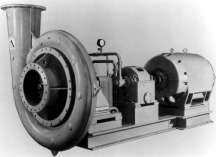
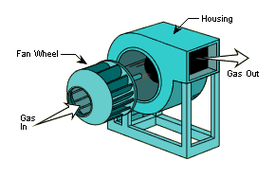
Centrifugal compressors are also similar to centrifugal fans of the style shown in neighboring figure as they both increase the flows energy through increasing radius.[1] In contrast to centrifugal fans, compressors operate at higher speeds to generate greater pressure rises. In many cases the engineering methods used to design a centrifugal fan are the same as those to design a centrifugal compressor. As a result, they can at times look very similar.
This relationship is less true in comparison to a squirrel-cage fan as shown in figure farthest right.
For purposes of generalization and definition, it can be said that centrifugal compressors often have density increases greater than 5 percent. Also, they often experience relative fluid velocities above Mach number 0.3[5][16] when the working fluid is air or nitrogen. In contrast, fans or blowers are often considered to have density increases of less than five percent and peak relative fluid velocities below Mach 0.3.
Centrifugal pump
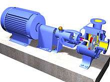
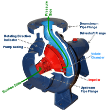
Centrifugal compressors are also similar to centrifugal pumps[1] of the style shown in the adjacent figures. The key difference between such compressors and pumps is that the compressor working fluid is a gas (compressible) and the pump working fluid is liquid (incompressible). Again, the engineering methods used to design a centrifugal pump are the same as those to design a centrifugal compressor. Yet, there is one important difference: the need to deal with cavitation in pumps.
Radial turbine
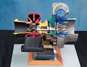
Centrifugal compressors also look very similar to their turbomachinery counterpart the radial turbine as shown in the figure. While a compressor transfers energy into a flow to raise its pressure, a turbine operates in reverse, by extracting energy from a flow, thus reducing its pressure.[7] In other words, power is input to compressors and output from turbines.
Turbomachinery using centrifugal compressors
A partial list of turbomachinery that may use one or more centrifugal compressors within the machine are listed here.
Components of a simple centrifugal compressor
A simple centrifugal compressor has four components: inlet, impeller/rotor, diffuser, and collector.[1] Figure 3.1 shows each of the components of the flow path, with the flow (working gas) entering the centrifugal impeller axially from right to left. As a result of the impeller rotating clockwise when looking downstream into the compressor, the flow will pass through the volute's discharge cone moving away from the figure's viewer.
Inlet
The inlet to a centrifugal compressor is typically a simple pipe. It may include features such as a valve, stationary vanes/airfoils (used to help swirl the flow) and both pressure and temperature instrumentation. All of these additional devices have important uses in the control of the centrifugal compressor.
Centrifugal impeller
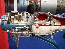
The key component that makes a compressor centrifugal is the centrifugal impeller, Figure 0.1, which contains a rotating set of vanes (or blades) that gradually raises the energy of the working gas. This is identical to an axial compressor with the exception that the gases can reach higher velocities and energy levels through the impeller's increasing radius. In many modern high-efficiency centrifugal compressors the gas exiting the impeller is traveling near the speed of sound.
Impellers are designed in many configurations including "open" (visible blades), "covered or shrouded", "with splitters" (every other inducer removed) and "w/o splitters" (all full blades). Both Figures 0.1 and 3.1 show open impellers with splitters. Most modern high efficiency impellers use "backsweep" in the blade shape.[6][17][18]
Euler’s pump and turbine equation plays an important role in understanding impeller performance.
Diffuser
The next key component to the simple centrifugal compressor is the diffuser.[7][8][18] Downstream of the impeller in the flow path, it is the diffuser's responsibility to convert the kinetic energy (high velocity) of the gas into pressure by gradually slowing (diffusing) the gas velocity. Diffusers can be vaneless, vaned or an alternating combination. High efficiency vaned diffusers are also designed over a wide range of solidities from less than 1 to over 4. Hybrid versions of vaned diffusers include: wedge, channel, and pipe diffusers. There are turbocharger applications that benefit by incorporating no diffuser.
Bernoulli's fluid dynamic principle plays an important role in understanding diffuser performance.
Collector
The collector of a centrifugal compressor can take many shapes and forms.[7][18] When the diffuser discharges into a large empty chamber, the collector may be termed a Plenum. When the diffuser discharges into a device that looks somewhat like a snail shell, bull's horn or a French horn, the collector is likely to be termed a volute or scroll. As the name implies, a collector’s purpose is to gather the flow from the diffuser discharge annulus and deliver this flow to a downstream pipe. Either the collector or the pipe may also contain valves and instrumentation to control the compressor.
Applications
Below, is a partial list of centrifugal compressor applications each with a brief description of some of the general characteristics possessed by those compressors. To start this list two of the most well-known centrifugal compressor applications are listed; gas turbines and turbochargers.[5]
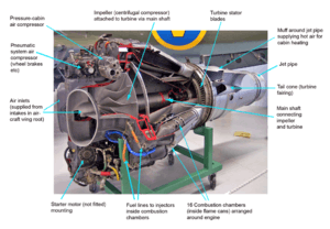

- In gas turbines and auxiliary power units.[19] Ref. Figures 4.1–4.2 In their simple form, modern gas turbines operate on the Brayton cycle. (ref Figure 5.1) Either or both axial and centrifugal compressors are used to provide compression. The types of gas turbines that most often include centrifugal compressors include turboshaft, turboprop, auxiliary power units, and micro-turbines. The industry standards applied to all of the centrifugal compressors used in aircraft applications are set by the FAA and the military to maximize both safety and durability under severe conditions. Centrifugal impellers used in gas turbines are commonly made from titanium alloy forgings. Their flow-path blades are commonly flank milled or point milled on 5-axis milling machines. When tolerances and clearances are the tightest, these designs are completed as hot operational geometry and deflected back into the cold geometry as required for manufacturing. This need arises from the impeller's deflections experienced from start-up to full speed/full temperature which can be 100 times larger than the expected hot running clearance of the impeller.
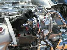
- In automotive engine and diesel engine turbochargers and superchargers.[20] Ref. Figure 1.1 Centrifugal compressors used in conjunction with reciprocating internal combustion engines are known as turbochargers if driven by the engine’s exhaust gas and turbo-superchargers if mechanically driven by the engine. Standards set by the industry for turbochargers may have been established by SAE.[21] Ideal gas properties often work well for the design, test and analysis of turbocharger centrifugal compressor performance.
- In pipeline compressors of natural gas to move the gas from the production site to the consumer.[22] Centrifugal compressors for such uses may be one- or multi-stage and driven by large gas turbines. Standards set by the industry (ANSI/API, ASME) result in large thick casings to maximize safety. The impellers are often if not always of the covered style which makes them look much like pump impellers. This type of compressor is also often termed an API-style. The power needed to drive these compressors is most often in the thousands of horsepower (HP). Use of real gas properties is needed to properly design, test and analyze the performance of natural gas pipeline centrifugal compressors.
- In oil refineries, natural gas processing, petrochemical and chemical plants.[22] Centrifugal compressors for such uses are often one-shaft multi-stage and driven by large steam or gas turbines. Their casings are often termed horizontally split or barrel. Standards set by the industry (ANSI/API, ASME) for these compressors result in large thick casings to maximize safety. The impellers are often if not always of the covered style which makes them look much like pump impellers. This type of compressor is also often termed API-style. The power needed to drive these compressors is most often in the thousands of HP. Use of real gas properties is needed to properly design, test and analyze their performance.
- Air-conditioning and refrigeration and HVAC: Centrifugal compressors quite often supply the compression in water chillers cycles.[23] Because of the wide variety of vapor compression cycles (thermodynamic cycle, thermodynamics) and the wide variety of workings gases (refrigerants), centrifugal compressors are used in a wide range of sizes and configurations. Use of real gas properties is needed to properly design, test and analyze the performance of these machines. Standards set by the industry for these compressors include ASHRAE, ASME & API.
- In industry and manufacturing to supply compressed air for all types of pneumatic tools.[24] Centrifugal compressors for such uses are often multistage and driven by electric motors. Inter-cooling is often needed between stages to control air temperature. Note that the road repair crew and the local automobile repair garage find screw compressors better adapt to their needs. Standards set by the industry for these compressors include ASME and government regulations that emphasize safety. Ideal gas relationships are often used to properly design, test and analyze the performance of these machines. Carrier’s equation is often used to deal with humidity.
- In air separation plants to manufacture purified end product gases.[24] Centrifugal compressors for such uses are often multistage using inter-cooling to control air temperature. Standards set by the industry for these compressors include ASME and government regulations that emphasize safety. Ideal gas relationships are often used to properly design, test and analyze the performance of these machines when the working gas is air or nitrogen. Other gases require real gas properties.
- In oil field re-injection of high pressure natural gas to improve oil recovery.[22] Centrifugal compressors for such uses are often one-shaft multi-stage and driven by gas turbines. With discharge pressures approaching 700 bar, casing are of the barrel style. Standards set by the industry (API, ASME) for these compressors result in large thick casings to maximize safety. The impellers are often if not always of the covered style which makes them look much like pump impellers. This type of compressor is also often termed API-style. Use of real gas properties is needed to properly design, test and analyze their performance.
Performance
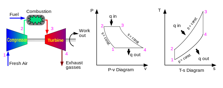

While illustrating a gas turbine's Brayton cycle,[12] Figure 5.1 includes example plots of pressure-specific volume and temperature-entropy. These types of plots are fundamental to understanding centrifugal compressor performance at one operating point. Studying these two plots further we see that the pressure rises between the compressor inlet (station 1) and compressor exit (station 2). At the same time, it is easy to see that the specific volume decreases or similarly the density increases. Studying the temperature-entropy plot we see the temperature increase with increasing entropy (loss). If we assume dry air, and ideal gas equation of state and an isentropic process, we have enough information to define the pressure ratio and efficiency for this one point. Unfortunately, we are missing several other key pieces of information if we wish to apply the centrifugal compressor to another application.
Figure 5.2, a centrifugal compressor performance map (either test or estimated), shows flow, pressure ratio for each of 4 speed-lines (total of 23 data points). Also included are constant efficiency contours. Centrifugal compressor performance presented in this form provides enough information to match the hardware represented by the map to a simple set of end-user requirements.
Compared to estimating performance which is very cost effective (thus useful in design), testing, while costly, is still the most precise method.[9] Further, testing centrifugal compressor performance is very complex. Professional societies such as ASME (i.e. PTC–10, Fluid Meters Handbook, PTC-19.x),[25] ASHRAE (ASHRAE Handbook) and API (ANSI/API 617-2002, 672-2007)[22][24] have established standards for detailed experimental methods and analysis of test results. Despite this complexity, a few basic concepts in performance can be presented by examining an example test performance map.
Performance maps
Pressure ratio and flow are the main parameters[12][22][24][25] needed to match the Figure 5.2 performance map to a simple compressor application. In this case, it can be assumed that the inlet temperature is sea-level standard. Making this assumption in a real case would be a significant error. A detailed inspection of Figure 5.2 shows:
- Corrected mass flow: 0.04 – 0.34 kg/s
- Total pressure ratio, inlet to discharge (PRt-t = Pt,discharge/Pt,inlet): 1.0 – 2.6
As is standard practice, Figure 5.2 has a horizontal axis labeled with a flow parameter. While flow measurements use a wide variety unit specifications, all fit one of 2 categories:
Mass flow per unit time
Mass flows, such as kg/s, are the easiest to use in practice as there is little room for confusion. Questions remaining would involve inlet or outlet (which might involve leakage from the compressor or moisture condensation). For atmospheric air, the mass flow may be wet or dry (including or excluding humidity). Often, the mass flow specification will be presented on an equivalent Mach number basis. It is standard in these cases that the equivalent temperature, equivalent pressure and gas is specified explicitly or implied at a standard condition.
Volume flow per unit time
In contrast, all volume flow specifications require the additional specification of density. Bernoulli's fluid dynamic principal is of great value in understanding this problem. Confusion arises through either inaccuracies or misuse of pressure, temperature and gas constants.
Also as is standard practice, Figure 5.2 has a vertical axis labeled with a pressure parameter. The variety of pressure measurement units is also vast. In this case, they all fit one of three categories:
- The delta increase or rise from inlet to exit (Manometer style)
- The measured discharge pressure (force)
- The force ratio (ratio, exit/inlet)
Other features common to performance maps are:
Constant speed lines
The two most common methods used for testing centrifugal compressors is to test along lines of constant shaft speed or along lines of constant throttle. If the shaft speed is held constant, test points are taken along a constant speed line by changing throttle positions. In contrast, if a throttle valve is held constant, test points are established by changing speed (common gas turbine practice). The map shown in Figure 5.2 illustrate the most common method; lines of constant speed. In this case we see data points connected via straight lines at speeds of 50%, 71%, 87%, and 100% RPM. The first three speed lines have 6 points each while the highest speed line has five.
Constant efficiency islands
The next feature to be discussed is the oval shaped curves representing islands of constant efficiency. In this figure we see 11 contours ranging from 56% efficiency (decimal 0.56) to 76% efficiency (decimal 0.76). General standard practice is to interpret these efficiencies as isentropic rather than polytropic. The inclusion of efficiency islands effectively generates a 3-dimensional topology to this 2-dimensional map. With inlet density specified, it provides a further ability to calculate aerodynamic power. Lines of constant power could just as easily be substituted.
Design or guarantee point(s)
Regarding gas turbine operation and performance, there may be a series of guaranteed points established for the gas turbine’s centrifugal compressor. These requirements are of secondary importance to the overall gas turbine performance as a whole. For this reason it is only necessary to summarize that in the ideal case, the lowest specific fuel consumption would occur when the centrifugal compressors peak efficiency curve coincides with the gas turbine's required operation line.
In contrast to gas turbines, most other applications (including industrial) need to meet a less stringent set of performance requirements. Historically, centrifugal compressors applied to industrial applications were needed to achieve performance at a specific flow and pressure. Modern industrial compressors are often needed to achieve specific performance goals across a range of flows and pressures; thus taking a significant step toward the sophistication seen in gas turbine applications.
If the compressor represented by Figure 5.2 is used in a simple application, any point (pressure and flow) within the 76% efficiency would provide very acceptable performance. An "End User" would be very happy with the performance requirements of 2.0 pressure ratio at 0.21 kg/s.
Surge
Surge - is the point at which the compressor cannot add enough energy to overcome the system resistance or backpressure.[26] This causes a rapid flow reversal (i.e., surge). As a result, high vibration, temperature increases, and rapid changes in axial thrust can occur. These occurrences can damage the rotor seals, rotor bearings, the compressor driver and cycle operation. Most turbomachines are designed to easily withstand occasional surging. However, if the machine is forced to surge repeatedly for a long period of time, or if it is poorly designed, repeated surges can result in a catastrophic failure. Of particular interest, is that while turbomachines may be very durable, the cycles/processes that they are used within can be far less robust.
Surge line
The surge-line shown in Figure 5.2 is the curve that passes through the lowest flow points of each of the four speed lines. As a test map, these points would be the lowest flow points possible to record a stable reading within the test facility/rig. In many industrial applications it may be necessary to increase the stall line due to the system backpressure. For example, at 100% RPM stalling flow might increase from approximately 0.170 kg/s to 0.215 kg/s because of the positive slope of the pressure ratio curve.
As stated earlier, the reason for this is that the high-speed line in Figure 5.2 exhibits a stalling characteristic or positive slope within that range of flows. When placed in a different system those lower flows might not be achievable because of interaction with that system. System resistance or adverse pressure is proven mathematically to be the critical contributor to compressor surge.
Maximum flow line versus choke
Choke occurs under one of 2 conditions. Typically for high speed equipment, as flow increases the velocity of the flow can approach sonic speed somewhere within the compressor stage. This location may occur at the impeller inlet "throat" or at the vaned diffuser inlet "throat". In contrast, for lower speed equipment, as flows increase, losses increase such that the pressure ratio eventually drops to 1:1. In this case, the occurrence of choke is unlikely.
The speed lines of gas turbine centrifugal compressors typically exhibit choke. This is a situation where the pressure ratio of a speed line drops rapidly (vertically) with little or no change in flow. In most cases the reason for this is that close to Mach 1 velocities have been reached somewhere within the impeller and/or diffuser generating a rapid increase in losses. Higher pressure ratio turbocharger centrifugal compressors exhibit this same phenomenon. Real choke phenomena is a function of compressibility as measured by the local Mach number within an area restriction within the centrifugal pressure stage.
The maximum flow line, shown in Figure 5.2, is the curve that passes through the highest flow points of each speed line. Upon inspection it may be noticed that each of these points has been taken near 56% efficiency. Selecting a low efficiency (<60%) is the most common practice used to terminate compressor performance maps at high flows. Another factor that is used to establish the maximum flow line is a pressure ratio near or equal to 1. The 50% speed line may be considered an example of this.
The shape of Figure 5.2's speed lines provides a good example of why it is inappropriate to use the term choke in association with a maximum flow of all centrifugal compressor speed lines. In summary; most industrial and commercial centrifugal compressors are selected or designed to operate at or near their highest efficiencies and to avoid operation at low efficiencies. For this reason there is seldom a reason to illustrate centrifugal compressor performance below 60% efficiency.
Many industrial and commercial multistage compressor performance maps exhibits this same vertical characteristic for a different reason related to what is known as stage stacking.
Other operating limits
- Minimum operating speed
- The minimum speed for acceptable operation, below this value the compressor may be controlled to stop or go into an "Idle" condition.
- Maximum allowable speed
- The maximum operating speed for the compressor. Beyond this value stresses may rise above prescribed limits and rotor vibrations may increase rapidly. At speeds above this level the equipment will likely become very dangerous and be controlled to lower speeds.
Dimensional analysis
To weigh the advantages between centrifugal compressors it is important to compare 8 parameters classic to turbomachinery. Specifically, pressure rise (p), flow (Q), angular speed (N), power (P), density (ρ), diameter (D), viscosity (μ) and elasticity (e). This creates a practical problem when trying to experimentally determine the effect of any one parameter. This is because it is nearly impossible to change one of these parameters independently.
The method of procedure known as the Buckingham π theorem can help solve this problem by generating 5 dimensionless forms of these parameters.[1][7][13] These Pi parameters provide the foundation for "similitude" and the "affinity-laws" in turbomachinery. They provide for the creation of additional relationships (being dimensionless) found valuable in the characterization of performance.
For the examples below Head will be substituted for pressure and sonic velocity will be substituted for elasticity.
Π theorem
The three independent dimensions used in this procedure for turbomachinery are:
- mass (force is an alternative)
- length
- time


According to the theorem each of the eight main parameters are equated to its independent dimensions as follows:
| Flow | ex. = m3/s | ||
| Head | ex. = kg·m/s2 | ||
| Speed | ex. = m/s | ||
| Power | ex. = kg·m2/s3 | ||
| Density | ex. = kg/m3 | ||
| Viscosity | ex. = kg/m·s | ||
| Diameter | ex. = m | ||
| Speed of sound | ex. = m/s |


Classic turbomachinery similitude
Completing the task of following the formal procedure results in generating this classic set of five dimensionless parameters for turbomachinery. Full similitude is achieved when each of the 5 Pi-parameters are equivalent. This of course would mean the two turbomachines being compared are geometrically similar and running at the same operating point.
| Flow coefficient | ||
| Head coefficient | ||
| Speed coefficient | ||
| Power coefficient | ||
| Reynolds coefficient |


Turbomachinery analysts gain tremendous insight into performance by comparisons of these 5 parameters with efficiencies and loss coefficients which are also dimensionless. In general application, the flow coefficient and head coefficient are considered of primary importance. Generally, for centrifugal compressors, the velocity coefficient is of secondary importance while the Reynolds coefficient is of tertiary importance. In contrast, as expected for pumps, the Reynolds number becomes of secondary importance and the velocity coefficient almost irrelevant. It may be found interesting that the speed coefficient may be chosen to define the y-axis of Figure 1.1, while at the same time the Reynolds coefficient may be chosen to define the z-axis.
Other dimensionless combinations
Demonstrated in the table below is another value of dimensional analysis. Any number of new dimensionless parameters can be calculated through exponents and multiplication. For example, a variation of the first parameter shown below is popularly used in aircraft engine system analysis. The third parameter is a simplified dimensional variation of the first and second. This third definition is applicable with strict limitations. The fourth parameter, specific speed, is very well known and useful in that it removes diameter. The fifth parameter, specific diameter, is a less often discussed dimensionless parameter found useful by Balje.[27]
| 1 | Corrected mass flow coefficient | ||
| 2 | Alternate#1 equivalent Mach form | ||
| 3 | Alternate#2 simplified dimensional form | ||
| 4 | Specific speed coefficient | ||
| 5 | Specific diameter coefficient |


It may be found interesting that the specific speed coefficient may be used in place of speed to define the y-axis of Figure 1.2, while at the same time, the specific diameter coefficient may be in place of diameter to define the z-axis.
Affinity laws
The following affinity laws are derived from the five Π-parameters shown above. They provide a simple basis for scaling turbomachinery from one application to the next.
| From flow coefficient | |||
| From head coefficient | |||
| From power coefficient |


Aero-thermodynamic fundamentals
The following equations outline a fully three-dimensional mathematical problem that is very difficult to solve even with simplifying assumptions.[5][28] Until recently, limitations in computational power, forced these equations to be simplified to an Inviscid two-dimensional problem with pseudo losses. Before the advent of computers, these equations were almost always simplified to a one-dimensional problem.
Solving this one-dimensional problem is still valuable today and is often termed mean-line analysis. Even with all of this simplification it still requires large textbooks to outline and large computer programs to solve practically.
Conservation of mass
Also termed continuity, this fundamental equation written in general form is as follows:

Conservation of momentum
Also termed the Navier–Stokes equations, this fundamental is derivable from Newton's second law when applied to fluid motion. Written in compressible form for a Newtonian fluid, this equation may be written as follows:

Conservation of energy
The First Law of Thermodynamics is the statement of the conservation of energy. Under specific conditions, the operation of a Centrifugal compressor is considered a reversible process. For a reversible process, the total amount of heat added to a system can be expressed as where is temperature and is entropy. Therefore, for a reversible process:


Since U, S and V are thermodynamic functions of state, the above relation holds also for non-reversible changes. The above equation is known as the fundamental thermodynamic relation.
Equation of state
The classical ideal gas law may be written:

The ideal gas law may also be expressed as follows

where is the density, is the adiabatic index (ratio of specific heats), is the internal energy per unit mass (the "specific internal energy"), is the specific heat at constant volume, and is the specific heat at constant pressure.


With regard to the equation of state, it is important to remember that while air and nitrogen properties (near standard atmospheric conditions) are easily and accurately estimated by this simple relationship, there are many centrifugal compressor applications where the ideal relationship is inadequate. For example, centrifugal compressors used for large air conditioning systems (water chillers) use a refrigerant as a working gas that cannot be modeled as an ideal gas. Another example are centrifugal compressors design and built for the petroleum industry. Most of the hydrocarbon gases such as methane and ethylene are best modeled as a real gas equation of state rather than ideal gases. The Wikipedia entry for equations of state is very thorough.
Pros and cons
- Pros
- Centrifugal compressors are used throughout industry because they have fewer rubbing parts, are relatively energy efficient, and give higher airflow than a similarly sized reciprocating compressor or positive-displacement compressor.
- Cons
- Their main drawback is that they cannot achieve the high compression ratio of reciprocating compressors without multiple stages. There are few one-stage centrifugal compressors capable of pressure ratios over 10:1, due to stress considerations which severely limit the compressor's safety, durability and life expectancy.
- Pros
- Centrifugal compressors are often used in small gas turbine engines like APUs (auxiliary power units) and smaller aircraft gas turbines. A significant reason for this is that with current technology, the equivalent flow axial compressor will be less efficient due primarily to a combination of rotor and variable stator tip-clearance losses. Further, they offer the advantages of simplicity of manufacturing and relatively low cost. This is due to requiring fewer stages to achieve the same pressure rise.
- Cons
- Centrifugal compressors are impractical, compared to axial compressors, for use in large gas turbine engines propelling large aircraft, due to the resulting weight and stress, and to the frontal area presented by the diffuser.
Structural mechanics, manufacture and design compromise
Ideally, centrifugal compressor impellers have thin airfoil blades that are strong, each mounted on a light rotor. This material would be easy to machine or cast and inexpensive. Additionally, it would generate no operating noise, have an life while operating in any environment.
From the very start of the aero-thermodynamic design process,the aerodynamic considerations and optimizations [29,30] are critical to have a successful design. during the design, the centrifugal impeller's material and manufacturing method must be accounted for within the design, whether it be plastic for a vacuum cleaner blower, aluminum alloy for a turbocharger, steel alloy for an air compressor or titanium alloy for a gas turbine. It is a combination of the centrifugal compressor impeller shape, its operating environment, its material and its manufacturing method that determines the impeller's structural integrity.
See also
- Three-dimensional losses and correlation in turbomachinery
- Effects of mach number and shock losses in turbomachines
References
- 1 2 3 4 5 6 7 8 9 10 11 12 13 14 Shepard, Dennis G. (1956). Principles of Turbomachinery. McMillan. ISBN 0-471-85546-4. LCCN 56002849.
- ↑ Aurel Stodola (1945). Steam and Gas Turbines. New York: P. Smith. OL 18625767M.
- ↑ Pfleiderer, C. (1952). Turbomachines. New York: Springer-Verlag.
- ↑ W. R. Hawthorne (1964). Aerodynamics Of Turbines and Compressors. Princeton New Jersey: Princeton University Press. LCCN 58-5029.
- 1 2 3 4 5 Lakshminarayana, B. (1996). Fluid Dynamics and Heat Transfer of Turbomachinery. New York: John Wiley & Sons Inc. ISBN 0-471-85546-4.
- 1 2 Japikse, David. Centrifugal Compressor Design and Performance. Concepts ETI . ISBN 0-933283-03-2.
- 1 2 3 4 5 6 Japikse, David & Baines, Nicholas C. (1997). Introduction to Turbomachinery. Oxford: Oxford University press. ISBN 0-933283-10-5.
- 1 2 Japikse, David and Baines, N.C. (1998). Diffuser Design Technology. Concepts ETI . ISBN 0-933283-01-6.
- 1 2 Japikse, David. Advanced Experimental Techniques in Turbomachinery. Concepts ETI. ISBN 0-933283-01-6.
- ↑ Peng, W. W. (2007). Fundamentals of Turbomachinery. New York: John Wiley & Sons Inc. ISBN 978-0-470-12422-2.
- 1 2 3 4 5 6 7 8 Wislicenus, George Friedrich (1965). Fluid Mechanics of Turbomachinery in two volumes. New York: Dover. ISBN 978-0-486-61345-1.
- 1 2 3 4 Wood, Bernard D. (1969). Applications of Thermodynamics. Reading, Massachusetts: Addison - Wesley Publishing Company. LCCN 75-79598.
- 1 2 3 Streeter, Victor L. (1971). Fluid Mechanics fifth edition. New York: McGraw Hill Book Company. ISBN 0-07-062191-8.
- ↑ Engeda, Abraham (1999). "From the Crystal Palace to the pump room". Mechanical Engineering. ASME.
- ↑ Elliott Company. "Past, Present, Future, 1910-2010" (PDF). Elliott. Retrieved 1 May 2011.
- ↑ API (July 2002). Std 673-2002 Centrifugal Fans for Petroleum, Chemical and Gas Industry Services. New York: API.
- ↑ Whitfield, A. & Baines, N. C. (1990). Design of Radial Turbomachinery. Longman Scientific and Technical. ISBN 0-470-21667-0.
- 1 2 3 Aungier, Ronald H. (2000). Centrifugal Compressors, A Strategy for Aerodynamic Design and Analysis. ASME Press. ISBN 0-7918-0093-8.
- ↑ Saravanamuttoo, H.I.H., Rogers, G.F.C. and Cohen, H. (2001). Gas Turbine Theory. Prentice-Hall. ISBN 0-13-015847-X.
- ↑ Baines, Nicholas C. (2005). Fundamentals of Turbocharging. Concepts ETI . ISBN 0-933283-14-8.
- ↑ "SAE Standards". SAE/standards/power and propulsion/engines. SAE International. Retrieved 23 April 2011.
- 1 2 3 4 5 API (July 2002). Std 617-2002 Axial and Centrifugal Compressors and Expander-compressors for Petroleum, Chemical and Gas Industry Services. New York: API.
- ↑ ASHRAE, American Society of Heating, Refrigeration and Air-Conditioning Engineers. "Standards & Guidelines". ASHRAE. Retrieved 23 April 2011.
- 1 2 3 4 API (October 2007). Std 672-2007 Packaged, Integrally Geared Centrifugal Air Compressors for Petroleum, Chemical, and Gas Industry Services. New York: API.
- 1 2 ASME PTC 10-1997 Test Code on Compressors and Exhausters. New York: ASME. 1997. ISBN 0-7918-2450-0.
- ↑ Pampreen, Ronald C. (1993). Compressor Surge and Stall. Concepts ETI. ISBN 0-933283-05-9.
- ↑ Balje, O. E. (1961). Turbo Machines; a Guide to Design, Selection, and Theory. New York: John Wiley & Sons. ISBN 0-471-06036-4.
- ↑ Cumpsty, N. A. (2004). Compressor Aerodynamics. Krieger Publishing. ISBN 1-57524-247-8.
- ↑ Xu, C. and R.S. Amano, The Development of a Centrifugal Compressor Impeller, International Journal for Computational Methods in Engineering Science and Mechanics, Volume 10 Issue 4 2009, Pages 290 – 301.
- ↑ Xu, C., Design experience and considerations for centrifugal compressor development., J. of Aerospace Eng. 2007
External links
| Wikimedia Commons has media related to Centrifugal compressors. |
- MIT Gas Turbine Laboratory
- (1948), First Marine Gas Turbine in Service. Journal of the American Society for Naval Engineers, 60: 66–86. doi:10.1111/j.1559-3584.1948.tb02754.x
- A history of Chrysler turbine cars
- To find API codes, standards & publications [Broken Link]
- To find ASME codes, standards & publications
- To find ASHRAE codes, standards & publications
- Glenn Research Center at NASA
- Pontyak Resource Centre
- Hydrodynamics of Pumps, by Christopher Earls Brennen