Radio transmitter design
A radio transmitter is an electronic device which, when connected to an antenna, produces an electromagnetic signal such as in radio and television broadcasting, two way communications or radar. Heating devices, such as a microwave oven, although of similar design, are not usually called transmitters, in that they use the electromagnetic energy locally rather than transmitting it to another location.
Design issues
A radio transmitter design has to meet certain requirements. These include the frequency of operation, the type of modulation, the stability and purity of the resulting signal, the efficiency of power use, and the power level required to meet the system design objectives.[1] High-power transmitters may have additional constraints with respect to radiation safety, generation of X-rays, and protection from high voltages.[2]
Typically a transmitter design includes generation of a carrier signal, which is normally[3] sinusoidal, optionally one or more frequency multiplication stages, a modulator, a power amplifier, and a filter and matching network to connect to an antenna. A very simple transmitter might contain only a continuously running oscillator coupled to some antenna system. More elaborate transmitters allow better control over the modulation of the emitted signal and improve the stability of the transmitted frequency. For example the Master Oscillator-Power Amplifier (MOPA) configuration inserts an amplifier stage between the oscillator and the antenna. This prevents changes in the loading presented by the antenna from altering the frequency of the oscillator.[4]
Determining the frequency
Fixed frequency systems
For a fixed frequency transmitter one commonly used method is to use a resonant quartz crystal in a Crystal oscillator to fix the frequency. Where the frequency has to be variable, several options can be used.
Variable frequency systems
- An array of crystals – used to enable a transmitter to be used on several different frequencies; rather than being a truly variable frequency system, it is a system which is fixed to several different frequencies (a subset of the above).
- Variable-frequency oscillator (VFO)
- Phase-locked loop frequency synthesiser
- Direct digital synthesis
Frequency multiplication
 Frequency doubler A push-push frequency doubler. The output is tuned to two times the input frequency. |
 Frequency tripler A push-pull frequency tripler. The output is tuned to three times the input frequency. |
While modern frequency synthesizers can output a clean stable signal up through UHF, for many years, especially at higher frequencies, it was not practical to operate the oscillator at the final output frequency. For better frequency stability, it was common to multiply the frequency of the oscillator up to the final, required frequency. This was accommodated by allocating the short wave amateur and marine bands in harmonically related frequencies such as 3.5, 7, 14 and 28 MHz. Thus one crystal or VFO could cover several bands. In simple equipment this approach is still used occasionally.
If the output of an amplifier stage is simply tuned to a multiple of the frequency with which the stage is driven, the stage will give a large harmonic output. Many transmitters have used this simple approach successfully. However these more complex circuits will do a better job. In a push-push stage, the output will only contain even harmonics. This is because the currents which would generate the fundamental and the odd harmonics in this circuit are canceled by the second device. In a push-pull stage, the output will contain only odd harmonics because of the canceling effect.
Adding modulation to the signal
The task of a transmitter is to convey some form of information using a radio signal (carrier wave) which has been modulated to carry the intelligence. The RF generator in a microwave oven, electrosurgery, and induction heating are similar in design to transmitters, but usually not considered as such in that they do not intentionally produce a signal that will travel to a distant point. Such RF devices are required by law to operate in an ISM band where interference to radio communications will not occur. Where communications is the object, one or more of the following methods of incorporating the desired signal into the radio wave is used.
AM modes
When the amplitude of a radio frequency wave is varied in amplitude in a manner which follows the modulating signal, usually voice, video or data, we have Amplitude modulation (AM).
Low level and high level
In low level modulation a small audio stage is used to modulate a low power stage. The output of this stage is then amplified using a linear RF amplifier. The great disadvantage of this system is that the amplifier chain is less efficient, because it has to be linear to preserve the modulation. Hence high efficiency class C amplifiers cannot be employed, unless a Doherty amplifier, EER (Envelope Elimination and Restoration) or other methods of predistortion or negative feedback are used. High level modulation uses class C amplifiers in a broadcast AM transmitter and only the final stage or final two stages are modulated, and all the earlier stages can be driven at a constant level. When modulation is applied to the plate of the final tube, a large audio amplifier is needed for the modulation stage, equal to 1/2 of the DC input power of the modulated stage. Traditionally the modulation is applied using a large audio transformer. However many different circuits have been used for high level AM modulation. See Amplitude Modulation.
Types of AM modulators
A wide range of different circuits have been used for AM. While it is perfectly possible to create good designs using solid-state electronics, valved (tube) circuits are shown here. In general, valves are able to easily yield RF powers far in excess of what can be achieved using solid state. Most high-power broadcast stations below 3 MHz use solid state circuits, but higher power stations above 3 MHz still use valves.
Plate AM modulators
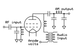
High level plate modulation consists of varying the voltage on the plate (anode) of the valve so that it swings from nearly zero to double the resting value. This will produce 100% modulation and can be done by inserting a transformer in series with the high voltage supply to the anode so that the vector sum of the two sources, (DC and audio) will be applied. A disadvantage is the size, weight and cost of the transformer as well as its limited audio frequency response, especially for very powerful transmitters.
Alternatively a series regulator can be inserted between the DC supply and the anode. The DC supply provides twice the normal voltage the anode sees. The regulator can allow none or all of the voltage to pass, or any intermediate value. The audio input operates the regulator in such a way as to produce the instantaneous anode voltage needed to reproduce the modulation envelope. An advantage of the series regulator is that it can set the anode voltage to any desired value. Thus the power output of the transmitter can be easily adjusted, allowing the use of Dynamic Carrier Control. The use of PDM switching regulators makes this system very efficient, whereas the original analog regulators were very inefficient and also non linear. Series PDM modulators are used in solid state transmitters also, but the circuits are somewhat more complex, using push pull or bridge circuits for the RF section.
These simplified diagrams omit such details as filament, screen and grid bias supplies, and the screen and cathode connections to RF ground.
Screen AM modulators

Under carrier conditions (no audio) the stage will be a simple RF amplifier where the screen voltage is set lower than normal to limit the RF output to about 25% of full power. When the stage is modulated the screen potential changes and so alters the gain of the stage. It takes much less audio power to modulate the screen, but final stage efficiency is only about 40%, compared to 80% with plate modulation. For this reason screen modulation was used only in low power transmitters and is now effectively obsolete.
AM related modes
Several derivatives of AM are in common use. These are
Single-sideband modulation
SSB, or SSB-AM single-sideband full carrier modulation, is very similar to single-sideband suppressed carrier modulation (SSB-SC). It is used where it is necessary to receive the audio on an AM receiver, while using less bandwidth than with double sideband AM. Due to high distortion, it is seldom used. Either SSB-AM or SSB-SC are produced by the following methods.
Filter method
Using a balanced mixer a double side band signal is generated, this is then passed through a very narrow bandpass filter to leave only one side-band.[5] By convention it is normal to use the upper sideband (USB) in communication systems, except for amateur radio when the carrier frequency is below 10 MHz. There the lower side band (LSB) is normally used.
Phasing method

The phasing method for the generation of single sideband signals uses a network which imposes a constant 90° phase shift on audio signals over the audio range of interest. This was difficult with analog methods but with DSP is very simple.
These audio outputs are each mixed in a linear balanced mixer with a carrier. The carrier drive for one of these mixers is also shifted by 90°. The outputs of these mixers are added in a linear circuit to give the SSB signal by phase cancellation of one of the sidebands. Connecting the 90° delayed signal from either the audio or the carrier (but not both) to the other mixer will reverse the sideband, so either USB or LSB is available with a simple DPDT switch.
Vestigial-sideband modulation
Vestigial-sideband modulation (VSB, or VSB-AM) is a type of modulation system commonly used in analogue TV systems. It is normal AM which has been passed through a filter which reduces one of the sidebands. Typically, components of the lower sideband more than 0.75 MHz or 1.25 MHz below the carrier will be heavily attenuated.
Morse
Morse code is usually sent using on-off keying of an unmodulated carrier (Continuous wave). No special modulator is required.
This interrupted carrier may be analyzed as an AM-modulated carrier. On-off keying produces sidebands, as expected, but they are referred to as "key-clicks". Shaping circuits are used to turn the transmitter on and off smoothly instead of instantly in order to limit the bandwidth of these sidebands and reduce interference to adjacent channels.
FM modes
Angle modulation is the proper term for modulation by changing the instantaneous frequency or phase of the carrier signal. True FM and phase modulation are the most commonly employed forms of analogue angle modulation.
Direct FM
Direct FM (true Frequency modulation) is where the frequency of an oscillator is altered to impose the modulation upon the carrier wave. This can be done by using a voltage-controlled capacitor (Varicap diode) in a crystal-controlled oscillator or frequency synthesiser. The frequency of the oscillator is then multiplied up using a frequency multiplier stage, or is translated upwards using a mixing stage, to the output frequency of the transmitter. The amount of modulation is referred to as the deviation, being the amount that the frequency of the carrier instantaneously deviates from the centre carrier frequency.
Indirect FM
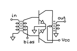
Indirect FM employs a varicap diode to impose a phase shift (which is voltage-controlled) in a tuned circuit that is fed with a plain carrier. This is termed phase modulation. In some indirect FM solid state circuits, an RF drive is applied to the base of a transistor. The tank circuit (LC), connected to the collector via a capacitor, contains a pair of varicap diodes. As the voltage applied to the varicaps is changed, the phase shift of the output will change.
Phase modulation is mathematically equivalent to direct Frequency modulation with a 6dB/octave high-pass filter applied to the modulating signal. This high-pass effect can be exploited or compensated for using suitable frequency-shaping circuitry in the audio stages ahead of the modulator. For example, many FM systems will employ pre-emphasis and de-emphasis for noise reduction, in which case the high-pass equivalency of phase modulation automatically provides for the pre-emphasis. Phase modulators are typically only capable of relatively small amounts of deviation while remaining linear, but any frequency multiplier stages also multiply the deviation in proportion.
Digital modes
Transmission of digital data is becoming more and more important. Digital information can be transmitted by AM and FM modulation, but often digital modulation consists of complex forms of modulation using aspects of both AM and FM. COFDM is used for DRM broadcasts. The transmitted signal consists of multiple carriers each modulated in both amplitude and phase. This allows very high bit rates and makes very efficient use of bandwidth. Digital or pulse methods also are used to transmit voice as in cell phones, or video as in terrestrial TV broadcasting. Early text messaging such as RTTY allowed the use of class C amplifiers, but modern digital modes require linear amplification.
See also Sigma-delta modulation (∑Δ)
Amplifying the signal
Valves
For high power, high frequency systems it is normal to use valves, please see [Valve RF amplifier] for details of how valved RF power stages work. Valves are electrically very robust, they can tolerate overloads which would destroy bipolar transistor systems in milliseconds. As a result, valved amplifiers may resist mistuning, lightning and power surges better. However, they require a heated cathode which consumes power and will fail in time due to loss of emission or heater burn out. The high voltages associated with valve circuits are dangerous to persons. For economic reasons, valves continue to be used for the final power amplifier for transmitters operating above 1.8 MHz and with powers above about 500 watts for amateur use and above about 10 Kw for broadcast use.
Solid state
Solid state devices, either discrete transistors or integrated circuits, are universally used for new transmitter designs up to a few hundred watts. The lower level stages of more powerful transmitters are also all solid state. Transistors can be used at all frequencies and power levels, but since the output of individual devices is limited, higher power transmitters must use many transistors in parallel, and the cost of the devices and the necessary combining networks can be excessive. As new transistor types become available and the price drops, solid state may eventually replace all valve amplifiers.
Linking the transmitter to the aerial
The majority of modern transmitting equipment is designed to operate with a resistive load fed via coaxial cable of a particular characteristic impedance, often 50 ohms. To connect the power stage of the transmitter to this coaxial cable transmission line a matching network is required. For solid state transmitters this is typically a broadband transformer which steps up the low impedance of the output devices to 50 ohms. A tube transmitter will contain a tuned output network, most commonly a PI network, that steps the load impedance which the tube requires down to 50 ohms. In each case the power producing devices will not transfer power efficiently if the network is detuned or badly designed or if the antenna presents other than 50 ohms at the transmitter output. Commonly an SWR meter and/or directional wattmeter are used to check the extent of the match between the aerial system and the transmitter via the transmission line (feeder). A directional wattmeter indicates forward power, reflected power, and often SWR as well. Each transmitter will specify a maximum allowable mismatch based on efficiency, distortion, and possible damage to the transmitter. Many transmitters have automatic circuits to reduce power or shut down if this value is exceeded.
Transmitters feeding a balanced transmission line will need a balun. This transforms the single ended output of the transmitter to a higher impedance balanced output. High power short wave transmission systems typically use 300 ohm balanced lines between the transmitter and antenna. Amateurs often use 300-450 ohm balanced antenna feeders.
See Antenna tuner and balun for details of matching networks and baluns respectively.
EMC matters
Many devices depend on the transmission and reception of radio waves for their operation. The possibility for mutual interference is great. Many devices not intended to transmit signals may do so. For instance a dielectric heater might contain a 2000 watt 27 MHz source within it. If the machine operates as intended then none of this RF power will leak out. However, if due to poor design or maintenance it allows RF to leak out, it will become a transmitter or unintentional radiator.
RF leakage & shielding
All equipment using RF electronics should be inside a screened conductive box and all connections in or out of the box should be filtered to avoid the passage of radio signals. A common and effective method of doing so for wires carrying DC supplies, 50/60 Hz AC connections, audio and control signals is to use a feedthrough capacitor, whose job is to short circuit any RF on the wire to ground. The use of ferrite beads is also common.
If an intentional transmitter produces interference, then it should be run into a dummy load; this is a resistor in a screened box or can which will allow the transmitter to generate radio signals without sending them to the antenna. If the transmitter continues to cause interference during this test then a path exists by which RF power is leaking out of the equipment and this can be due to bad shielding. Such leakage is most likely to occur on homemade equipment or equipment that has been modified or had covers removed. RF leakage from microwave ovens, while rare, may occur due to defective door seals, and may be a health hazard.
Spurious emissions
Early in the development of radio technology it was recognized that the signals emitted by transmitters had to be 'pure'. Spark-gap transmitters were outlawed once better technology was available as they give an output which is very wide in terms of frequency. The term spurious emissions refers to any signal which comes out of a transmitter other than the wanted signal. In modern equipment there are three main types of spurious emissions: harmonics, out of band mixer products which are not fully suppressed and leakage from the local oscillator and other systems within the transmitter.
Harmonics
These are multiples of the operation frequency of the transmitter, they can be generated in any stage of the transmitter which is not perfectly linear and must be removed by filtering.
Avoiding harmonic generation
 This push pull wide band amplifier uses ferrite core transformers for matching and coupling. The two NPN transistors can be biased to class A, AB or C, and will still have very weak harmonics at even multiples of the design frequency. The odd harmonics will be stronger, but still manageable. Class C will have the most harmonics. |
 This single ended amplifier uses a narrowly tuned anode circuit to reduce harmonics when operating class AB or C. |
The difficulty of removing harmonics from an amplifier will depend on the design. A push-pull amplifier will have fewer harmonics than a single ended circuit. A class A amplifier will have very few harmonics, class AB or B more, and class C the most. In the typical class C amplifier, the resonant tank circuit will remove most of the harmonics, but in either of these examples, a low pass filter will likely be needed following the amplifier.
Removal of harmonics with filters

In addition to the good design of the amplifier stages, the transmitter's output should be filtered with a low pass filter to reduce the level of the harmonics. Typically the input and output are interchangeable and match to 50 ohms. Inductance and capacity values will vary with frequency. Many transmitters switch in a suitable filter for the frequency band being used. The filter will pass the desired frequency and reduce all harmonics to acceptable levels.
The harmonic output of a transmitter is best checked using an RF spectrum analyzer or by tuning a receiver to the various harmonics. If a harmonic falls on a frequency being used by another communications service then this spurious emission can prevent an important signal from being received. Sometimes additional filtering is used to protect a sensitive range of frequencies, for example, frequencies used by aircraft or services involved with protection of life and property. Even if a harmonic is within the legally allowed limits, the harmonic should be further reduced.
Oscillators and mix products


When mixing signals to produce a desired output frequency, the choice of Intermediate frequency and local oscillator is important. If poorly chosen, a spurious output can be generated. For example if 50 MHz is mixed with 94 MHz to produce an output on 144 MHz, the third harmonic of the 50 MHz may appear in the output. This problem is similar to the Image response problem which exists in receivers.
One method of reducing the potential for this transmitter defect is the use of balanced and double balanced mixers. A simple mixer will pass both of the input frequencies and all of their harmonics along with the sum and difference frequencies. If the simple mixer is replaced with a balanced mixer then the number of possible products is reduced. If the frequency mixer has fewer outputs the task of making sure that the final output is clean will be simpler.
Instability and parasitics
If a stage in a transmitter is unstable and is able to oscillate then it can start to generate RF at either a frequency close to the operating frequency or at a very different frequency. One good sign that it is occurring is if an RF stage has a power output even without being driven by an exciting stage. Output power should increase smoothly as input power is increased, although with Class C, there will be a noticeable threshold effect. Various circuits are used for parasitic suppression in a good design. Proper neutralization is also important.
Control and protection

One button and two knobs allow control of 52 separate parameters.
The simplest transmitters such as RFID devices require no external controls. Simple tracking transmitters may have only an on-off switch. Many transmitters must have circuits that allow them to be turned on and off and the power output and frequency adjusted or modulation levels adjusted. Many modern multi-featured transmitters allow the adjustment of many different parameters. Usually these are under microprocessor control via multilevel menus, thus reducing the required number of physical knobs. Often a display screen provides feedback to the operator to assist in adjustments. The user friendliness of this interface will often be one of the main factors in a successful design.
Microprocessor controlled transmitters also may include software to prevent off frequency or other illegal operation. Transmitters using significant power or expensive components must also have protection circuits which prevent such things as overload, overheating or other abuse of the circuits. Overload circuits may include mechanical relays, or electronic circuits. Simple fuses may be included to protect expensive components. Arc detectors may shut off the transmitter when sparks or fires occur.
Protection features must also prevent the human operator and the public from encountering the high voltages and power which exist inside the transmitter. Tube transmitters typically use DC voltages between 600 and 30,000 volts, which are deadly if contacted. Radio frequency power above about 10 watts can cause burning of human tissue through contact and higher power can actually cook human flesh without contact. Metal shielding is required to isolate these dangers. Properly designed transmitters have doors or panels which are interlocked, so that open doors activate switches which do not allow the transmitter to be turned on when the dangerous areas are exposed. In addition, either resistors which bleed off the high voltages or shorting relays are employed to insure that capacitors do not retain a dangerous charge after turn off.
With large high power transmitters, the protective circuits can comprise a significant fraction of the total design complexity and cost.
Power supplies
Some RFID devices take power from an external source when it interrogates the device, but most transmitters either have self-contained batteries, or are mobile systems which typically operate directly from the 12 volt vehicle battery. Larger fixed transmitters will require power from the mains. The voltages used by a transmitter will be AC and DC of many different values. Either AC transformers or DC power supplies are required to provide the values of voltage and current needed to operate the various circuits. Some of these voltages will need to be regulated. Thus a significant part of the total design will consist of power supplies. Power supplies will be integrated into the control and protection systems of the transmitter, which will turn them on in the proper sequence and protect them from overloads. Often rather complicated logic systems will be required for these functions.
See also
| The Wikibook Electronics has a page on the topic of: Transmitter design |
- Distributed active transformer – low-voltage transistors used to generate radio frequencies
References
- Citations and notes
- ↑ Rudolf F. Graf, William Sheets, Build Your Own Low-Power Transmitters: Projects for the Electronics Experimenter Newnes, 2001 ISBN 0750672447, page 2
- ↑ Ronald Kitchen, RF Radiation Safety Handbook, Butterworth Heinemann 1993, ISBN 0 7506 1712 8 Chapter 10
- ↑ some spread spectrum systems use pulses or sets of orthogonal wave forms
- ↑ Joseph J. Carr Microwave and Wireless Communication Technology, Newnes, 1997 ISBN 0750697075 page 339-341
- ↑ Pappenfus, Bruene and Schoenike Single sideband principles and circuits McGraw-Hill, 1964, chapter 6
- General information
- American Radio Relay League. (2012).The ARRL Handbook for Radio Communications.| ISBN 978-0-87259-663-4|url=http://www.arrl.org/arrl-handbook-2013
- Radio Society of Great Britain. (2005). Radio communication handbook. Potters Bar, Hertfordshire [England]: Radio Society of Great Britain. ISBN 0-900612-58-4
- Terman, Electronics and Radio Engineering. McGraw-Hill
- Frederick H. Raab, et al. (May 2003). "RF and Microwave Power Amplifier and Transmitter Technologies - Part 2". High Frequency Design: p. 22ff. http://www.scribd.com/doc/8616046/RF-Power-Amplifier-and-Transmitter-Technologies-Part2
- Historical interest
- Bucher, E. E. (1921). Practical wireless telegraphy; a complete text book for students of radio communication. New York [etc.]: Wireless Press.<Link is Broken>
- Sleeper, M. B. (1922). Design data for radio transmitters and receivers. Everyday engineering series, [no.] 6. New York: Norman W. Henley Pub.<Link is Broken>