Tamping machine

A tamping machine or ballast tamper is a machine used to pack (or tamp) the track ballast under railway tracks to make the tracks more durable. Prior to the introduction of mechanical tampers, this task was done by manual labour with the help of beaters. As well as being faster, more accurate, more efficient and less labour-intensive, tamping machines are essential for the use of concrete sleepers since they are too heavy (usually over 250 kg (551 lb)) to be lifted by hand. Whilst also available as a plain tamper with no lifting or lining function this article will focus on the multi function machines.
Early machines only lifted the track and packed the ballast. More modern machines, sometimes known as a tamper-liner or tamping and lining machine, also correct the alignment of the rails to make them parallel and level, in order to achieve a more comfortable ride for passengers and freight and to reduce the mechanical strain applied to the rails by passing trains. This is done by finding places where the sleepers have sunk from the weight of the passing trains or frost action, causing the track to sag. The tamper lifts each sleeper and the rails up, and packs ballast underneath. When the sleeper is laid down again, the sagged rails now sit at the proper level. In cases where frost action has caused adjacent rails to rise higher, ballast tampers can raise rails above their original level to make the line level again. "Lining" rails doesn't involve ballast tamping, it merely ensures the rails are perfectly parallel and straight as possible. Combining tamping and lining into a single machine saves time and money, as only one machine needs to be run over the track to perform both functions.
Functions
- Packing of ballast under sleepers
- Correction of cross level
- Correction of longitudinal level
- Driving
- Run drive
- Work drive
- Special functions
- Twist corrections
- Track settlement
- Laser lining
- Automatic data feeding by computer
- Recording of track parameter
Types

Tamper machines are built in many different varieties depending on their purpose:
- Plain line tamping machines: used on line sections which have no points or other complex track structures, commonly referred to as production machines, generally have fixed tamping head positions
- Duomatic
- Continuous action tamping machines
- Tamping Express
- Switch tamping machines: used to tamp switches, crossings and other complex track structures, have movable tamping heads with ability to isolate heads when required.
Tamping process
The tamping process from any type of tamper consists of the following basic steps:
- Lifting, lining unit moves rail and sleepers under tamping unit into correct vertical and horizontal position
- Tamping units drive vibrating tines into the ballast on both sides of the sleeper until squeezing depth is achieved
- Vibrating tines are pushed together to pack ballast under lifted, lined sleeper to ensure it holds position when released by the lifting, lining unit
- Tamping unit retracts to stowage position, track is released by lifting, lining unit
- Machine moves to the next sleeper and begins a new cycle
Standard tamping machine arrangement
The basic principles and functions of a tamping machine remain the same regardless of manufacturer with only minor differences in design.
Drive
The majority of track machines are powered by a diesel engine. This provides power to the driving wheels via either a hydrostatic circuit or cardan shaft, allowing the machine to propel itself to and around a work-site. The engine also drives an hydraulic pump to provide power for the various tools.
Lifting Lining Unit
The lifting lining unit of a tamping machine is used to lift and hold the track in corrected position while being tamped. all types of units require the following components to achieve this task:
- Chassis, normally rectangular with 4 wheels to ride on the rails
- Lifting cylinders, 1 cylinder on either side connecting the unit to main machine chassis and allowing unit to lift track vertically
- Lining cylinders, 2 horizontal cylinders between unit chassis and main machine chassis used to push/pull the track horizontally
- Clamp or "hook" assemblies, these are usually on the outside of each rail and utilize hydraulic cylinders to clamp onto the side of the rail head so that is locked to the unit chassis before lifting and lining is commenced
The lifting lining unit is usually secured to the main machine chassis via an hydraulically length adjustable trailing arm, The arm is adjustable so that the unit can be moved clear of small obstructions such as insulated joints or wires.
Reference system
To ensure track geometry is corrected most tamping machines use a 2 chord lining system ( 1 for vertical alignment and 1 for horizontal alignment). The 2 chord system requires 3 reference trolleys fitted to the machine usually called A point, B point and C point. some machines will use a 4th point in between B and C to carry out quality control measurements.
A point is always the front reference point and sits on uncorrected track, the anchorage for chords on A point are able to moved to compensate for defects in track geometry, this is done by the "tower"operator. Depending on chord system the anchorages will be either a wire anchor or a light source.
B point is positioned as close as physically possible to the lifting lining unit. B point is used by the machine control system to position the track correctly using either potentiometers or optical filters depending on type of chord system used
C point is the rear most measuring point and anchorage point for lifting and lining chords depending on type of chord system C point will be either wire anchor with tensioning cylinder or a photo electric light receiver.
All 3 points are individual rail trolleys able to freely move up, down, left and right independent of the machine chassis and hence follow any minor fluctuation in rail position. When working the machine uses pneumatic cylinders to lightly push these trolleys into the selected datum rail both vertically and horizontally.
When using this method the tower operator positions A point anchorages according to existing track geometry measurements taken beforehand. Once A point has been positioned it is then assumed that both A and C are in correct position as if machine were sitting on corrected track. the machine then uses the lifting lining unit to move the rail and B point in line with A and C.
Tamping units
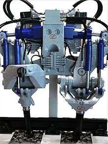
The Tamping units of most Tamping machines will consist of:
- A set of tines either 8 or 16 per sleeper divided evenly between front and rear of sleeper
- Mounting or "guide" rods that allow the unit as a whole to move up and down in a linear motion
- Support frame
- Squeezing arms
- Tine mounts, can be either part of the squeezing arm or attached to it via a pin to allow swiveling depending on type of tamping machine
To generate the vibration needed for penetration and consolidation there are two leading methods commonly used:
- Using a hydraulically driven eccentric shaft attached either to the end of the squeezing cylinders or acting as the pivot point for the squeezing arms
- Using a special squeezing cylinder and valve assembly to oscillate the tines
A less common method more often seen on tamping head attachments for excavators is to use a motor driven vibrator assembly that is directly bolted to the support frame.
Specialist tamping machines
Continuous Action Tamping Machines
A Continuous Action Tamping Machine (CAT) can pack between one and four sleepers at a time, with outputs between 320m/h and 2600m/h generally anticipated.[1]
Dynamic Tamping Express
The 'Tamping Express' is a machine developed by Plasser & Theurer, and in the UK & Europe is referred to as the 09-3X. This machine consists of a conventional CAT styllish satellite with tooling for 3 sleepers in continuous succession, along with a full DTS stabilising unit suspended from the rear most vehicle in the machine.[2]
DGS / DTS (Dynamic Track Stabilising)
Tamping and cleaning operations have the adverse effect of reducing the resistance of the track to lateral movement. The resistance gradually recovers with the passage of trains, but may require a speed restriction imposed for the duration. This 'consolidation' can be achieved faster and in a more controlled manner using mechanised equipment known as the Dynamic Track Stabiliser (DTS).
A DTS will normally be used only after a stretch of track has been tamped and aligned.
D.G.S. has a vibrating unit which holds the track in position and applies a horizontal vibration and vertical load to simulate the passage of trains. The track parameters (or cross levels), before and after stabilising, can be viewed through bogies in the front and rear.
Dynamic Track Stabilising has the following advantages, resulting in enhanced safety:
- Increases the resistance of the track to lateral movement
- Creates a homegenous bed of ballast
- Permits earlier relaxation of speed restrictions
- Eliminates non-uniform initial differential settlements caused by rail traffic
- Retains correct track geometry for a longer period than was achievable using tamping machines alone
- Vibration frequency: 30–35 Hz
- Working speed: 1–2 km/h
- Vertical pressure applied: 100 kg/cm²
The stabilisation achieved by one pass of a D.G.S. is equal to that achieved by 100,000 tonnes of traffic, and allows a speed restriction of 20 km/h to be relaxed to 40 km/h
Dynamic stabilisation is usually avoided on bridges or around overhead structures since there is a risk of damage to foundations.
Image gallery
 Polish tamping machine
 French tamping machine
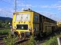 German tamping machine
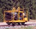 Czech narrow gauge tamping machine
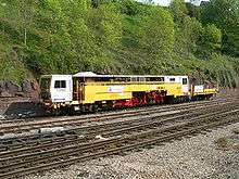
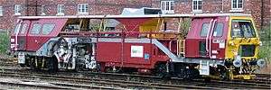
 Amey Plc tamping machine
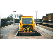
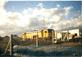 Amey Plc tamping machine
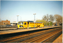
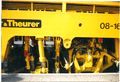 Amey Plc tamping machine
 Amey Plc tamping machine
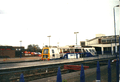 Balfour Beatty tamping machine
 Balfour Beatty tamping machine
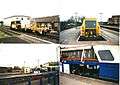 Balfour Beatty and Carillion tamping machine
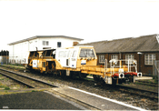 Carillion tamping machine
 A Multiple-Tie-Tamper seen at Sagamiko Station in Sagamihara, Kanagawa, Japan
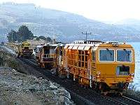 Plasser and Theurer DGS 62 N dynamic track stabilizer, followed by SSP 300 Regulator, then a Plasser 09-16 CAT Continuous Action Tamper, in Blueskin Bay, New Zealand.
See also
References
- ↑ "09-4X Dynamic Tamping Express". PlasserAmerican.com. Plasser & Theurer. 2010. Archived from the original on 23 August 2013. Retrieved 16 January 2015.
- ↑ "09-3X Dynamic Tamping Express". PlasserAmerican.com. Plasser & Theurer. 2010. Archived from the original on 27 December 2012. Retrieved 16 January 2015.
Further reading
- Indian Railway Track Design, Construction, Maintenance & Modernisation – M.M. Agarwal (former Chief Engineer, Northern Railway, New Delhi) Hony. Adviser, Institution of P.way Engineers (India), Railway Board Office, New Delhi—ISBN 81-900613-1-3
- Plasser and Theurer Track Geometry Maintenance Durability Seminar, Athens, 11 October 2011, Ing. Rudolf Becker
- YouTube video of Iarnród Éireann Tamper: https://www.youtube.com/watch?v=pmnX7L_nQBQ
- Cox, Steve (27 August – 9 September 1997). "Keeping the lines straight". RAIL. No. 312. EMAP Apex Publications. pp. 30–34. ISSN 0953-4563. OCLC 49953699.
- System 7 fully hydraulic tamping drive https://www.youtube.com/watch?v=_l68_5mA5Wk
- "Track Compendium" DW Media group GmbH I Eurailpress
External links
| Wikimedia Commons has media related to Ballast tampers. |
- Audio recording of tamping machine
- Photos of dynamic track stabilisers in the UK
- Photos of tampers in the UK
- http://s7australia.com/system7-products/rail-tamping/