X-ray optics
X-ray optics is the branch of optics that manipulates X-rays instead of visible light. While lenses for visible light are made of transparent materials that can have a refractive index substantially larger than 1, for X-rays the index of refraction is slightly smaller than unity.[1] The principal methods to manipulate X-rays are therefore by reflection, diffraction and interference. Examples of applications include X-ray microscopes and X-ray telescopes. Refraction is the basis for the compound refractive lens, many small X-ray lenses in series that compensate by their number for the X-rays' minute index of refraction. The imaginary part of the refractive index, corresponding to absorption, can also be used to manipulate X-rays: one example is the pin-hole camera, which also works for visible light.
Reflection
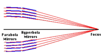
The basic idea is to reflect a beam of X-rays from a surface and to measure the intensity of X-rays reflected in the specular direction (reflected angle equal to incident angle). It has been shown that a reflection off a parabolic mirror followed by a reflection off a hyperbolic mirror can lead to the focusing of X-rays.[2] Since the incoming X-rays must strike the tilted surface of the mirror, the collecting area is small. It can, however, be increased by nesting arrangements of mirrors inside each other.[3]
The ratio of reflected intensity to incident intensity is the X-ray reflectivity for the surface. If the interface is not perfectly sharp and smooth, the reflected intensity will deviate from that predicted by the law of Fresnel reflectivity. The deviations can then be analyzed to obtain the density profile of the interface normal to the surface. For films with multiple layers, X-ray reflectivity may show oscillations with wavelength, analogous to the Fabry-Pérot effect. These oscillations can be used to infer layer thicknesses and other properties.
Diffraction

In X-ray diffraction a beam strikes a crystal and diffracts into many specific directions. The angles and intensities of the diffracted beams indicate a three-dimensional density of electrons within the crystal. X-rays produce a diffraction pattern because their wavelength is typically the same order of magnitude (0.1-10.0 nm) as the spacing between the atomic planes in the crystal.
Each atom re-radiates a small portion of an incoming beam's intensity as a spherical wave. If the atoms are arranged symmetrically (as is found in a crystal) with a separation d, these spherical waves will be in synch (add constructively) only in directions where their path-length difference 2d sin θ is equal to an integer multiple of the wavelength λ. The incoming beam therefore appears to have been deflected by an angle 2θ, producing a reflection spot in the diffraction pattern.
X-ray diffraction is a form of elastic scattering; the outgoing X-rays have the same energy, and thus same wavelength, as the incoming X-rays, only with altered direction. By contrast, inelastic scattering occurs when energy is transferred from the incoming X-ray to an inner-shell electron exciting it to a higher energy level. Such inelastic scattering reduces the energy (or increases the wavelength) of the outgoing beam. Inelastic scattering is useful for probing such electron excitation, but not in determining the distribution of atoms within the crystal.
Longer-wavelength photons (such as ultraviolet radiation) would not have sufficient resolution to determine the atomic positions. At the other extreme, shorter-wavelength photons such as gamma rays are difficult to produce in large numbers, difficult to focus, and interact too strongly with matter, producing particle-antiparticle pairs.
Similar diffraction patterns can be produced by scattering electrons or neutrons. X-rays are usually not diffracted from atomic nuclei.
Interference
X-ray interference is the addition (superposition) of two or more X-ray waves that results in a new wave pattern. X-ray interference usually refers to the interaction of waves that are correlated or coherent with each other, either because they come from the same source or because they have the same or nearly the same frequency.
Two non-monochromatic X-ray waves are only fully coherent with each other if they both have exactly the same range of wavelengths and the same phase differences at each of the constituent wavelengths.
The total phase difference is derived from the sum of both the path difference and the initial phase difference (if the X-ray waves are generated from two or more different sources). It can then be concluded whether the X-ray waves reaching a point are in phase (constructive interference) or out of phase (destructive interference).
Technologies
There are a variety of techniques used to funnel X-ray photons to the appropriate location on an X-ray detector:
- Grazing incidence mirrors in a Wolter telescope,[2][4][5] or a Kirkpatrick-Baez X-ray reflection microscope,
- Zone plates,
- Bent crystals,[6]
- Normal-incidence mirrors making use of multilayer coatings,
- A normal-incidence lens much like an optical lens, such as a compound refractive lens,
- Microstructured optical arrays, namely capillary/polycapillary optical systems,[7][8][9][10]
- Coded aperture imaging, or
- Modulation collimators,
- X-ray waveguides.
Most X-ray optical elements (with the exception of grazing incidence mirrors) are very small, and must be designed for a particular incident angle and energy, thus limiting their applications in divergent radiation. Although the technology has advanced rapidly, its practical uses are still limited. One of the applications showing greater promise is in enhancing both the contrast and resolution of mammographic images, compared to conventional anti-scatter grids.
Mirrors for X-ray optics
The mirrors can be made of glass, ceramic or metal foil, coated by a reflective layer.[1] The most commonly used reflective materials for X-ray mirrors are gold and iridium. Even with these the critical reflection angle is energy dependent. For gold at 1 keV, the critical reflection angle is 2.4 degrees.[11]
The utilization of X-ray mirrors simultaneously requires:
- the ability to determine the location of the arrival of an X-ray photon in two dimensions
- a reasonable detection efficiency.
Hard X-ray mirrors
An X-ray mirror optic for NuStar space telescope working up 79 keV, was made using multi-layered coatings, computer aided manufacturing, and other techniques.[12] The mirrors use a Tungsten (W)/Silicon (Si) or Platinum(Pt)/Silicon Carbide(SiC) multi-coating on slumped glass, allowing a Wolter telescope design.[12]
This was thought to be the limit at that time but a discovery in 2012 may allow focusing gamma-ray telescopes.[13] At photon energies greater than 700 keV, the index of refraction starts to increase again.[13]
References
- 1 2 Spiller, E (2003). "X-Ray Optics". Encyclopedia of Optical Engineering: Taylor & Francis. doi:10.1081/E-EOE-120009497.
- 1 2 Rob Petre. "X-ray Imaging Systems". NASA.
- ↑ Bradt, Hale (2007). Astronomy Methods. Cambridge University Press. p. 106. ISBN 978 0 521 53551 9.
- ↑ Wolter, H. (1952). "Glancing Incidence Mirror Systems as Imaging Optics for X-rays". Annalen der Physik. 10: 94. Bibcode:1952AnP...445...94W. doi:10.1002/andp.19524450108.
- ↑ Wolter, H. (1952). "A Generalized Schwarschild Mirror Systems For Use at Glancing Incidence for X-ray Imaging". Annalen der Physik. 10: 286. Bibcode:1952AnP...445..286W. doi:10.1002/andp.19524450410.
- ↑ Pikuz, T.A.; Faenov, A.Ya.; Fraenkel, M.; Zigler, A.; Flora, F.; Bollanti, S.; Di Lazzaro, P.; Letardi, T.; Grilli, A.; Palladino, L.; Tomassetti, G.; Reale, A.; Reale, L.; Scafati, A.; Limongi, T.; Bonfigli, F.; Alainelli, L.; Sanchez del Rio, M. (2000). "Using spherically bent crystals for obtaining high-resolution, large-field, monochromatic X-ray backlighting imaging for wide range of Bragg angles". Proceedings of the 27th IEEE International Conference on Plasma Science. Plasma Science. p. 183.
- ↑ Kumakhov, MA (1990). "Channeling of photons and new X-ray optics". Nuclear Instruments and Methods in Physics Research Section B. 48 (1–4): 283–286. Bibcode:1990NIMPB..48..283K. doi:10.1016/0168-583X(90)90123-C.
- ↑ Dabagov, SB (2003). "Channeling of neutral particles in micro- and nanocapillaries". Physics-Uspekhi. 46 (10): 1053–1075. Bibcode:2003PhyU...46.1053D. doi:10.1070/PU2003v046n10ABEH001639.
- ↑ An introduction to X-Ray Optics
- ↑ Polycapillary Optics
- ↑ "CXRO X-Ray Interactions With Matter". henke.lbl.gov. Retrieved 2016-02-19.
- 1 2 NuStar: Instrumentation: Optics Archived November 1, 2010, at the Wayback Machine.
- 1 2 Tim Wogan - Silicon 'prism' bends gamma rays (May 2012) - PhysicsWorld.com
See also
- X-ray telescope
- Wolter telescope, a type of X-ray telescope built with glancing incidence mirrors
- XMM-Newton and Chandra X-ray Observatory, orbiting observatories using X-ray optics
- X-ray spectroscopy, X-ray photoelectron spectroscopy, X-ray crystallography