Video camera tube

The video camera tube was a type of cathode ray tube used to capture the television image prior to the introduction of charge-coupled devices (CCDs) in the 1970s. Several different types of tubes were in use from the early 1930s to the 1980s.
In these tubes, the cathode ray was scanned across an image of the scene to be broadcast. The resultant current was dependent on the brightness of the image on the target. The size of the striking ray was tiny compared to the size of the target, allowing 483 horizontal scan lines per image in the NTSC format, or 576 lines in PAL.[1]
Cathode ray tube
Any vacuum tube which operates using a focused beam of electrons, "cathode rays", is known as a cathode ray tube (CRT). However, in the popular lexicon "CRT" usually refers to the "picture tube" in a CRT television. With the introduction of the personal computer in the early 1980s, "cathode ray tube" (quickly replaced by the acronym "CRT") became the word used for the display, which looked like a small television. It is only one of many types of cathode ray tubes. Other CRTs include the tubes used in television, oscilloscopes, or radar displays. The camera pickup tubes described in this article are also CRTs, but they display no image, and are not kinescopes.[2]
Early research
In June 1908, the scientific journal Nature published a letter in which Alan Archibald Campbell-Swinton, fellow of the Royal Society (UK), discussed how a fully electronic television system could be realized by using cathode ray tubes (or "Braun" tubes, after its inventor, Karl Braun) as both imaging and display devices.[3] He noted that the "real difficulties lie in devising an efficient transmitter", and that it was possible that "no photoelectric phenomenon at present known will provide what is required".[4] A cathode ray tube was successfully demonstrated as a displaying device by the German Professor Max Dieckmann in 1906, his experimental results were published by the journal Scientific American in 1909.[5] Campbell-Swinton later expanded on his vision in a presidential address given to the Röntgen Society in November 1911. The photoelectric screen in the proposed transmitting device was a mosaic of isolated rubidium cubes.[6][7] His concept for a fully electronic television system was later popularized by Hugo Gernsback as the "Campbell-Swinton Electronic Scanning System" in the August 1915 issue of the popular magazine Electrical Experimenter.[8][9][10]
In a letter to Nature published in October 1926, Campbell-Swinton also announced the results of some "not very successful experiments" he had conducted with G. M. Minchin and J. C. M. Stanton. They had attempted to generate an electrical signal by projecting an image onto a selenium-coated metal plate that was simultaneously scanned by a cathode ray beam.[11][12] These experiments were conducted before March 1914, when Minchin died,[13] but they were later repeated by two different teams in 1937, by H. Miller and J. W. Strange from EMI,[14] and by H. Iams and A. Rose from RCA.[15] Both teams succeeded in transmitting "very faint" images with the original Campbell-Swinton's selenium-coated plate, but much better images were obtained when the metal plate was covered with zinc sulphide or selenide,[14] or with aluminum or zirconium oxide treated with caesium.[15] These experiments are the base of the future vidicon. A description of a CRT imaging device also appeared in a patent application filed by Edvard-Gustav Schoultz in France in August 1921, and published in 1922,[16] although a working device was not demonstrated until some years later.[15]
Image dissector

An image dissector is a camera tube that creates an "electron image" of a scene from photocathode emissions (electrons) which pass through a scanning aperture to an anode, which serves as an electron detector.[17][18] Among the first to design such a device were German inventors Max Dieckmann and Rudolf Hell,[19][20] who had titled their 1925 patent application Lichtelektrische Bildzerlegerröhre für Fernseher (Photoelectric Image Dissector Tube for Television).[21] The term may apply specifically to a dissector tube employing magnetic fields to keep the electron image in focus,[18] an element lacking in Dieckmann and Hell's design, and in the early dissector tubes built by American inventor Philo Farnsworth.[19][22]
Dieckmann and Hell submitted their application to the German patent office in April 1925, and a patent was issued in October 1927.[21] Their experiments on the image dissector were announced in the volume 8 (September 1927) of the popular magazine Discovery[23][24] and in the May 1928 issue of the magazine Popular Radio.[25] However, they never transmitted a clear and well focused image with such a tube.
In January 1927, Farnsworth applied for a patent for his Television System that included a device for "the conversion and dissecting of light".[22] Its first moving image was successfully transmitted on September 7 of 1927,[26] and a patent was issued in 1930.[22] Farnsworth quickly made improvements to the device, among them introducing an electron multiplier made of nickel[27][28] and deploying a "longitudinal magnetic field" in order to sharply focus the electron image.[29] The improved device was demonstrated to the press in early September 1928.[19][30][31] The introduction of a multipactor in October 1933[32][33] and a multi-dynode "electron multiplier" in 1937[34][35] made Farnsworth's image dissector the first practical version of a fully electronic imaging device for television.[36] Unfortunately, it had very poor light sensitivity, and was therefore primarily useful only where illumination was exceptionally high (typically over 685 cd/m²).[37][38][39] However, it was ideal for industrial applications, such as monitoring the bright interior of an industrial furnace. Due to their poor light sensitivity, image dissectors were rarely used in television broadcasting, except to scan film and other transparencies.
In April 1933, Farnsworth submitted a patent application also entitled Image Dissector, but which actually detailed a CRT-type camera tube.[40] This is among the first patents to propose the use of a "low-velocity" scanning beam and RCA had to buy it in order to sell image orthicon tubes to the general public.[41] However, Farnsworth never transmitted a clear and well focused image with such a tube.[42][43]
Operation
The optical system of the image dissector focuses an image onto a photocathode mounted inside a high vacuum. As light strikes the photocathode, electrons are emitted in proportion to the intensity of the light (see photoelectric effect). The entire electron image is deflected and a scanning aperture permits only those electrons emanating from a very small area of the photocathode to be captured by the detector at any given time. The output from the detector is an electric current whose magnitude is a measure of the brightness of the corresponding area of the image. The electron image is periodically deflected horizontally and vertically ("raster scanning") such that the entire image is read by the detector many times per second, producing an electrical signal that can be conveyed to a display device, such as a CRT monitor, to reproduce the image.[17][18]
The image dissector has no "charge storage" characteristic; the vast majority of electrons emitted by the photocathode are excluded by the scanning aperture,[20] and thus wasted rather than being stored on a photo-sensitive target, as in the iconoscope or image orthicon (see below), which largely accounts for its low light sensitivity.
Iconoscope

An iconoscope is a camera tube that projects an image on a special "charge storage" plate containing a mosaic of electrically isolated photosensitive granules separated from a common plate by a thin layer of isolating material, somewhat analogous to the human eye's retina and its arrangement of photoreceptors. Each photosensitive granule constitutes a tiny capacitor that accumulates and stores electrical charge in response to the light striking it. An electron beam periodically sweeps across the plate, effectively scanning the stored image and discharging each capacitor in turn such that the electrical output from each capacitor is proportional to the average intensity of the light striking it between each discharge event.[44][45]
The problem of low sensitivity to light resulting in low electrical output from transmitting or "camera" tubes would be solved with the introduction of charge-storage technology by the Hungarian engineer Kálmán Tihanyi in the beginning of 1925.[46] His solution was a camera tube that accumulated and stored electrical charges ("photoelectrons") within the tube throughout each scanning cycle. The device was first described in a patent application he filed in Hungary in March 1926 for a television system he dubbed "Radioskop".[47] After further refinements included in a 1928 patent application,[46] Tihanyi's patent was declared void in Great Britain in 1930,[48] and so he applied for patents in the United States.
Zworykin presented in 1923 his project for a totally electronic television system to the general manager of Westinghouse. In July 1925, Zworykin submitted a patent application titled Television System that included a charge storage plate constructed of a thin layer of isolating material (aluminum oxide) sandwiched between a screen (300 mesh) and a colloidal deposit of photoelectric material (potassium hydride) consisting of isolated globules.[49] The following description can be read between lines 1 and 9 in page 2: "The photoelectric material, such as potassium hydride, is evaporated on the aluminum oxide, or other insulating medium, and treated so as to form a colloidal deposit of potassium hydride consisting of minute globules. Each globule is very active photoelectrically and constitutes, to all intents and purposes, a minute individual photoelectric cell". Its first image was transmitted in late summer of 1925,[50] and a patent was issued in 1928.[49] However the quality of the transmitted image failed to impress H.P. Davis, the general manager of Westinghouse, and Zworykin was asked "to work on something useful".[50] A patent for a television system was also filed by Zworykin in 1923, but this filing is not a definitive reference because extensive revisions were done before a patent was issued fifteen years later[41] and the file itself was divided into two patents in 1931.[51][52]
The first practical iconoscope was constructed in 1931 by Sanford Essig, when he accidentally left a silvered mica sheet in the oven too long. Upon examination with a microscope, he noticed that the silver layer had broken up into a myriad of tiny isolated silver globules.[53] He also noticed that, "the tiny dimension of the silver droplets would enhance the image resolution of the iconoscope by a quantum leap."[54] As head of television development at Radio Corporation of America (RCA), Zworykin submitted a patent application in November 1931, and it was issued in 1935.[45] Nevertheless, Zworykin's team was not the only engineering group working on devices that used a charge stage plate. In 1932, the EMI engineers Tedham and McGee under the supervision of Isaac Shoenberg applied for a patent for a new device they dubbed the "Emitron".[55] A 405-line broadcasting service employing the Emitron began at studios in Alexandra Palace in 1936, and patents were issued in the United Kingdom in 1934 and in the USA in 1937.[56]
The iconoscope was presented to the general public at a press conference in June 1933,[57] and two detailed technical papers were published in September and October of the same year.[58][59] Unlike the Farnsworth image dissector, the Zworykin iconoscope was much more sensitive, useful with an illumination on the target between 4ft-c (43lx) and 20ft-c (215lx). It was also easier to manufacture and produced a very clear image. The iconoscope was the primary camera tube used by RCA broadcasting from 1936 until 1946, when it was replaced by the image orthicon tube.[60][61]
Super-Emitron and image iconoscope
The original iconoscope was noisy, had a high ratio of interference to signal, and ultimately gave disappointing results, especially when compared to the high definition mechanical scanning systems then becoming available.[62][63] The EMI team under the supervision of Isaac Shoenberg analyzed how the Emitron (or iconoscope) produces an electronic signal and concluded that its real efficiency was only about 5% of the theoretical maximum. This is because secondary electrons released from the mosaic of the charge storage plate when the scanning beam sweeps across it may be attracted back to the positively charged mosaic, thus neutralizing many of the stored charges.[64] Lubszynski, Rodda, and McGee realized that the best solution was to separate the photo-emission function from the charge storage one, and so communicated their results to Zworykin.[63][64]
The new video camera tube developed by Lubszynski, Rodda and McGee in 1934 was dubbed "the super-Emitron". This tube is a combination of the image dissector and the Emitron. It has an efficient photocathode that transforms the scene light into an electron image; the latter is then accelerated towards a target specially prepared for the emission of secondary electrons. Each individual electron from the electron image produces several secondary electrons after reaching the target, so that an amplification effect is produced. The target is constructed of a mosaic of electrically isolated metallic granules separated from a common plate by a thin layer of isolating material, so that the positive charge resulting from the secondary emission is stored in the granules. Finally, an electron beam periodically sweeps across the target, effectively scanning the stored image, discharging each granule, and producing an electronic signal like in the iconoscope.[65][66][67]
The super-Emitron was between ten and fifteen times more sensitive than the original Emitron and iconoscope tubes and, in some cases, this ratio was considerably greater.[64] It was used for an outside broadcasting by the BBC, for the first time, on Armistice Day 1937, when the general public could watch in a television set how the King lay a wreath at the Cenotaph. This was the first time that anyone could broadcast a live street scene from cameras installed on the roof of neighbor buildings.[68]
On the other hand, in 1934, Zworykin shared some patent rights with the German licensee company Telefunken.[69] The "image iconoscope" ("Superikonoskop" in Germany) was produced as a results of the collaboration. This tube is essentially identical to the super-Emitron, but the target is constructed of a thin layer of isolating material placed on top of a conductive base, the mosaic of metallic granules is missing. The production and commercialization of the super-Emitron and image iconoscope in Europe were not affected by the patent war between Zworykin and Farnsworth, because Dieckmann and Hell had priority in Germany for the invention of the image dissector, having submitted a patent application for their Lichtelektrische Bildzerlegerröhre für Fernseher (Photoelectric Image Dissector Tube for Television) in Germany in 1925,[21] two years before Farnsworth did the same in the United States.[22]
The image iconoscope (Superikonoskop) became the industrial standard for public broadcasting in Europe from 1936 until 1960, when it was replaced by the vidicon and plumbicon tubes. Indeed, it was the representative of the European tradition in electronic tubes competing against the American tradition represented by the image orthicon.[70][71] The German company Heimann produced the Superikonoskop for the 1936 Berlin Olympic Games,[72][73] later Heimann also produced and commercialized it from 1940 to 1955,[74] finally the Dutch company Philips produced and commercialized the image iconoscope and multicon from 1952 to 1958.[71][75]
Operation
The super-Emitron is a combination of the image dissector and the Emitron. The scene image is projected onto an efficient continuous-film semitransparent photocathode that transforms the scene light into a light-emitted electron image, the latter is then accelerated (and focused) via electromagnetic fields towards a target specially prepared for the emission of secondary electrons. Each individual electron from the electron image produces several secondary electrons after reaching the target, so that an amplification effect is produced, and the resulting positive charge is proportional to the integrated intensity of the scene light. The target is constructed of a mosaic of electrically isolated metallic granules separated from a common plate by a thin layer of isolating material, so that the positive charge resulting from the secondary emission is stored in the capacitor formed by the metallic granule and the common plate. Finally, an electron beam periodically sweeps across the target, effectively scanning the stored image and discharging each capacitor in turn such that the electrical output from each capacitor is proportional to the average intensity of the scene light between each discharge event (as in the iconoscope).[65][66][67]
The image iconoscope is essentially identical to the super-Emitron, but the target is constructed of a thin layer of isolating material placed on top of a conductive base, the mosaic of metallic granules is missing. Therefore, secondary electrons are emitted from the surface of the isolating material when the electron image reaches the target, and the resulting positive charges are stored directly onto the surface of the isolated material.[70]
Orthicon and CPS Emitron
The original iconoscope was very noisy[62] due to the secondary electrons released from the photoelectric mosaic of the charge storage plate when the scanning beam swept it across.[64] An obvious solution was to scan the mosaic with an electron beam, which velocity and energy were so low in a neighborhood of the plate, that no secondary electrons were emitted at all. That is, an image is projected onto the photoelectric mosaic of a charge storage plate, so that positive charges are produced and stored there due to photo-emission and capacitance, respectively. These stored charges are then "gently" discharged by a low-velocity electron scanning beam, preventing the emission of secondary electrons.[76][77] Not all the electrons in the scanning beam may be absorbed in the mosaic, because the stored positive charges are proportional to the integrated intensity of the scene light. The remaining electrons are then deflected back into the anode,[40][44] captured by a special grid,[78][79][80] or deflected back into an electron multiplier.[81]
Low-velocity scanning beam tubes have several advantages; there are low levels of spurious signals and high efficiency of conversion of light into signal, so that the signal output is maximum. However, there are serious problems as well, because the electron beam "spreads" and accelerates in a direction parallel to the target when it scans the image's borders and corners, so that it produces secondary electrons and one gets an image that is well focused in the center but blurry in the borders.[43][82] Henroteau was among the first inventors to propose in 1929 the use of low-velocity electrons for stabilizing the potential of a charge storage plate,[83] but Lubszynski and the EMI team were the first engineers in transmitting a clear and well focused image with such a tube.[42] Another improvement is the use of a semitransparent charge storage plate. The scene image is then projected onto the back side of the plate, while the low-velocity electron beam scans the photoelectric mosaic at the front side. This configurations allows the use of a straight camera tube, because the scene to be transmitted, the charge storage plate, and the electron gun can be aligned one after the other.[77]
The first fully functional low-velocity scanning beam tube, the CPS Emitron, was invented and demonstrated by the EMI team under the supervision of Isaac Shoenberg. In 1934, the EMI engineers Blumlein and McGee filed for patents for television transmitting systems where a charge storage plate was shielded by a pair of special grids, a negative (or slightly positive) grid lay very close to the plate, and a positive one was placed further away.[78][79][80] The velocity and energy of the electrons in the scanning beam were reduced to zero by the decelerating electric field generated by this pair of grids, and so a low-velocity scanning beam tube was obtained.[76][84] The EMI team kept working on these devices, and Lubszynski discovered in 1936 that a clear image could be produced if the trajectory of the low-velocity scanning beam was nearly perpendicular (orthogonal) to the charge storage plate in a neighborhood of it.[42][85] The resulting device was dubbed the cathode potential stabilized Emitron, or CPS Emitron.[76][86] The industrial production and commercialization of the CPS Emitron had to wait until the end of the second world war.[84][87]
On the other side of the ocean, the RCA team led by Albert Rose began working in 1937 on a low-velocity scanning beam device they dubbed the orthicon.[88] Iams and Rose solved the problem of guiding the beam and keeping it in focus by installing specially designed deflection plates and deflection coils near the charge storage plate to provide a uniform axial magnetic field.[43][81][89] The orthicon was the tube used in RCA's television demonstration at the 1939 New York World's Fair,[88] its performance was similar to the image iconoscope's one,[90] but it was also unstable under sudden flashes of bright light, producing "the appearance of a large drop of water evaporating slowly over part of the scene".[77]
Image orthicon
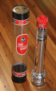
The image orthicon, (sometimes abbreviated IO) was common in American broadcasting from 1946 until 1968.[91] A combination of the image dissector and the orthicon technologies, it replaced the iconoscope in the USA, which required a great deal of light to work adequately.[92]
The image orthicon tube was developed at RCA by Albert Rose, Paul K. Weimer, and Harold B. Law. It represented a considerable advance in the television field, and after further development work, RCA created original models between 1939 and 1940.[93] The National Defense Research Committee entered into a contract with RCA where the NDRC paid for its further development. Upon RCA's development of the more sensitive image orthicon tube in 1943, RCA entered into a production contract with the U.S. Navy, the first tubes being delivered in January 1944.[94] RCA began production of image orthicons for civilian use in the second quarter of 1946.[61][95]
While the iconoscope and the intermediate orthicon used capacitance between a multitude of small but discrete light sensitive collectors and an isolated signal plate for reading video information, the image orthicon employed direct charge readings from a continuous electronically charged collector. The resultant signal was immune to most extraneous signal "crosstalk" from other parts of the target, and could yield extremely detailed images. For instance, image orthicon cameras were used for capturing Apollo/Saturn rockets nearing orbit after the networks had phased them out, as only they could provide sufficient detail.[96]
An image orthicon camera can take television pictures by candlelight because of the more ordered light-sensitive area and the presence of an electron multiplier at the base of the tube, which operated as a high-efficiency amplifier. It also has a logarithmic light sensitivity curve similar to the human eye. However, it tends to flare in bright light, causing a dark halo to be seen around the object; this anomaly is referred to as "blooming" in the broadcast industry when image orthicon tubes were in operation.[97] Image orthicons were used extensively in the early color television cameras, where the increased sensitivity of the tube was essential to overcome their very inefficient optical system of the other parts of the camera.[97][98]
Operation
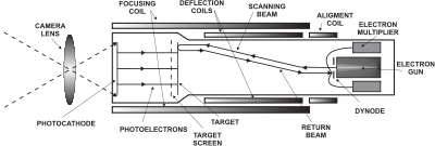
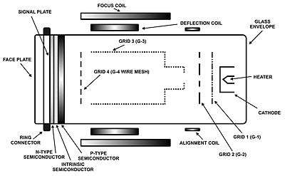
An image orthicon consists of three parts: a photocathode with an image store ("target"), a scanner that reads this image (an electron gun), and a multistage electron multiplier.[99]
In the image store, light falls upon the photocathode which is a photosensitive plate at a very negative potential (approx. -600 V), and is converted into an electron image (a principle borrowed from the image dissector). This electron rain is then accelerated towards the target (a very thin glass plate acting as a semi-isolator) at ground potential (0 V), and passes through a very fine wire mesh (near 200 wires per cm), very near (a few hundredths of cm) and parallel to the target, acting as a screen grid at a slightly positive voltage (approx +2 V). Once the image electrons reach the target, they cause a "splash" of electrons by the effect of secondary emission. On average, each image electron ejects several "splash" electrons (thus adding amplification by secondary emission), and these excess electrons are soaked up by the positive mesh effectively removing electrons from the target and causing a positive charge on it in relation to the incident light in the photocathode. The result is an image painted in positive charge, with the brightest portions having the largest positive charge. [100]
A sharply focused beam of electrons (a cathode ray) is generated by the electron gun at ground potential and accelerated by the anode (the first dynode of the electron multiplier) around the gun at a high positive voltage (approx. +1500 V). Once it exits the electron gun, its inertia makes the beam move away from the dynode towards the back side of the target. At this point the electrons lose speed and get deflected by the horizontal and vertical deflection coils, effectively scanning the target. Thanks to the axial magnetic field of the focusing coil, this deflection is not in a straight line, thus when the electrons reach the target they do so perpendicularly avoiding a sideways component. The target is nearly at ground potential with a small positive charge, thus when the electrons reach the target at low speed they are absorbed without ejecting more electrons. This adds negative charge to the positive charge until the region being scanned reaches some threshold negative charge, at which point the scanning electrons are reflected by the negative potential rather than absorbed (in this process the target recovers the electrons needed for the next scan). These reflected electrons return down the cathode ray tube toward the first dynode of the electron multiplier surrounding the electron gun which is at high potential. The number of reflected electrons is a linear measure of the target's original positive charge, which, in turn, is a measure of brightness.[101]
Dark halo
The mysterious dark "orthicon halo" around bright objects in an IO-captured image is based on the fact that the IO relies on the emission of photoelectrons, but very bright illumination can produce more of them locally than the device can successfully deal with. At a very bright point on a captured image, a great preponderance of electrons is ejected from the photosensitive plate. So many may be ejected that the corresponding point on the collection mesh can no longer soak them up, and thus they fall back to nearby spots on the target instead, much as water splashes in a ring when a rock is thrown into it. Since the resultant splashed electrons do not contain sufficient energy to eject further electrons where they land, they will instead neutralize any positive charge that has been built-up in that region. Since darker images produce less positive charge on the target, the excess electrons deposited by the splash will be read as a dark region by the scanning electron beam.
This effect was actually "cultivated" by tube manufacturers to a certain extent, as a small, carefully controlled amount of the dark halo has the effect of "crispening" the visual image due to the contrast effect. (That is, giving the illusion of being more sharply focused than it actually is). The later Vidicon tube and its descendants (see below) do not exhibit this effect, and so could not be used for broadcast purposes until special "detail correction" circuitry could be developed.[102]
Vidicon
A vidicon tube is a video camera tube design in which the target material is a photoconductor. The Vidicon was developed in the 1950s at RCA by P. K. Weimer, S. V. Forgue and R. R. Goodrich as a simple alternative to the structurally and electrically complex Image Orthicon. While the initial photoconductor used was selenium, other targets–including silicon diode arrays–have been used.

The vidicon is a storage-type camera tube in which a charge-density pattern is formed by the imaged scene radiation on a photoconductive surface which is then scanned by a beam of low-velocity electrons. The fluctuating voltage coupled out to a video amplifier can be used to reproduce the scene being imaged. The electrical charge produced by an image will remain in the face plate until it is scanned or until the charge dissipates. Pyroelectric photocathodes can be used to produce a vidicon sensitive over a broad portion of the infrared spectrum.
Prior to the design and construction of the Galileo probe to Jupiter in the late 1970s to early 1980s, NASA used Vidicon cameras on most of their unmanned deep space probes equipped with the remote sensing ability.[103] Vidicon tubes were also used aboard the first two Landsat earth imaging satellites launched in 1972, as part of each spacecraft's Return Beam Vidicon (RBV) imaging system.
Vidicon tubes were popular in 1970s and 1980s after which they were rendered obsolete by CCD and CMOS sensors.
Plumbicon
Plumbicon is a registered trademark of Philips for its Lead(II) oxide (PbO) target vidicons. Used frequently in broadcast camera applications, these tubes have low output, but a high signal-to-noise ratio. They had excellent resolution compared to Image Orthicons, but lacked the artificially sharp edges of IO tubes, which caused some of the viewing audience to perceive them as softer. CBS Labs invented the first outboard edge enhancement circuits to sharpen the edges of Plumbicon generated images.[104][105][106]
Compared to Saticons, Plumbicons had much higher resistance to burn in, and comet and trailing artifacts from bright lights in the shot. Saticons though, usually had slightly higher resolution. After 1980, and the introduction of the diode gun plumbicon tube, the resolution of both types was so high, compared to the maximum limits of the broadcasting standard, that the Saticon's resolution advantage became moot. While broadcast cameras migrated to solid state Charged Coupled Devices, plumbicon tubes remain a staple imaging device in the medical field.[104][105][106]
Narragansett Imaging is the only company now making Plumbicons, and it does so from the factories Philips built for that purpose in Rhode Island, USA. While still a part of the Philips empire, the company purchased EEV's (English Electric Valve) lead oxide camera tube business, and gained a monopoly in lead oxide tube production.[104][105][106]
Saticon
Saticon is a registered trademark of Hitachi also produced by Thomson and Sony. It was developed in a joint effort by Hitachi and NHK (Japan Broadcasting Corporation). Its surface consists of Selenium with trace amounts of Arsenic and Tellurium added (SeAsTe) to make the signal more stable. SAT in the name is derived from (SeAsTe).
Pasecon
Pasecon is a registered trademark of Heimann. Its surface consists of Cadmium selenide (CdSe).
Newvicon
Newvicon is a registered trademark of Matsushita. The Newvicon tubes were characterized by high light sensitivity. Its surface consists of a combination of Zinc selenide (ZnSe) and Zinc Cadmium Telluride (ZnCdTe).
Trinicon
Trinicon is a registered trademark of Sony. It uses a vertically striped RGB color filter over the faceplate of an otherwise standard vidicon imaging tube to segment the scan into corresponding red, green and blue segments. Only one tube was used in the camera, instead of a tube for each color, as was standard for color cameras used in television broadcasting. It is used mostly in low-end consumer cameras and camcorders, though Sony also used it in some moderate cost professional cameras in the 1980s, such as the DXC-1800 and BVP-1 models.[107]
Although the idea of using color stripe filters over the target was not new, the Trinicon was the only tube to use the primary RGB colors. This necessitated an additional electrode buried in the target to detect where the scanning electron beam was relative to the stripe filter. Previous color stripe systems had used colors where the color circuitry was able to separate the colors purely from the relative amplitudes of the signals. As a result, the Trinicon featured a larger dynamic range of operation.
Light biasing
All the vidicon type tubes except the vidicon itself were able to use a light biasing technique to improve the sensitivity and contrast. The photosensitive target in these tubes suffered from the limitation that the light level had to rise to a particular level before any video output resulted. Light biasing was a method whereby the photosensitive target was illuminated from a light source just enough that no appreciable output was obtained, but such that a slight increase in light level from the scene was enough to provide discernible output. The light came from either an illuminator mounted around the target, or in more professional cameras from a light source on the base of the tube and guided to the target by light piping. The technique would not work with the baseline vidicon tube because it suffered from the limitation that as the target was fundamentally an insulator, the constant low light level built up a charge which would manifest itself as a form of 'fogging'. The other types had semiconducting targets which did not have this problem.
Color cameras
Early color cameras used the obvious technique of using separate red, green and blue image tubes in conjunction with a color separator, a technique still in use with 3CCD solid state cameras today. It was also possible to construct a color camera that used a single image tube. One technique has already been described (Trinicon above). A more common technique and a simpler one from the tube construction standpoint was to overlay the photosensitive target with a color striped filter having a fine pattern of vertical stripes of green, cyan and clear filters (i.e. Green; Green+Blue & Green+Blue+Red) repeating across the target. The advantage of this arrangement was that for virtually every color, the video level of the green component was always less than the cyan, and similarly the cyan was always less than the white. Thus the contributing images could be separated without any reference electrodes in the tube. If the three levels were the same, then that part of the scene was green. This method suffered from the disadvantage that the light levels under the three filters were almost certain to be different, with the green filter passing not more than one third of the available light.
Variations on this scheme exist, the principal one being to use two filters with color stripes overlaid such that the colors form vertically oriented lozenge shapes overlaying the target. The method of extracting the color is similar however.
Field-sequential color system
During the 1930s and 1940s, Field-sequential color systems were developed which used synchronized motor-driven color-filter disks at the camera's image tube and at the television receiver. Each disk consisted of red, blue, and green transparent color filters. In the camera, the disk was in the optical path, and in the receiver, it was in front of the CRT. Disk rotation was synchronized with vertical scanning so that each vertical scan in sequence was for a different primary color. This method allowed regular black-and-white image tubes and CRTs to generate and display color images. A field-sequential system developed by Peter Goldmark for CBS was demonstrated to the press on September 4, 1940,[108] and was first shown to the general public on January 12, 1950.[109] Guillermo González Camarena developed a field-sequential color disk system in the early 1940s, for which he received the first US patent for color television in 1942.[110]
Magnetic focusing in typical camera tubes
The phenomenon known as magnetic focusing was discovered by A. A. Campbell-Swinton in 1896, he found that a longitudinal magnetic field generated by an axial coil can focus an electron beam.[111] This phenomenon was immediately corroborated by J. A. Fleming, and Hans Busch gave a complete mathematical interpretation in 1926.[112]
Diagrams in this article show that the focus coil surrounds the camera tube; it is much longer than the focus coils for earlier TV CRTs. Camera-tube focus coils, by themselves, have essentially parallel lines of force, very different from the localized semi-toroidal magnetic field geometry inside a TV receiver CRT focus coil. The latter is essentially a magnetic lens; it focuses the "crossover" (between the CRT's cathode and G1 electrode, where the electrons pinch together and diverge again) onto the screen.
The electron optics of camera tubes differ considerably. Electrons inside these long focus coils take helical paths as they travel along the length of the tube. The center (think local axis) of one of those helices is like a line of force of the magnetic field. While the electrons are traveling, the helices essentially don't matter. Assuming that they start from a point, the electrons will focus to a point again at a distance determined by the strength of the field. Focusing a tube with this kind of coil is simply a matter of trimming the coil's current. In effect, the electrons travel along the lines of force, although helically, in detail.
These focus coils are essentially as long as the tubes themselves, and surround the deflection yoke (coils). Deflection fields bend the lines of force (with negligible defocusing), and the electrons follow the lines of force.
In a conventional magnetically deflected CRT, such as in a TV receiver or computer monitor, basically the vertical deflection coils are equivalent to coils wound around an horizontal axis. That axis is perpendicular to the neck of the tube; lines of force are basically horizontal. (In detail, coils in a deflection yoke extend some distance beyond the neck of the tube, and lie close to the flare of the bulb; they have a truly distinctive appearance.)
In a magnetically focused camera tube (there are electrostatically focused vidicons), the vertical deflection coils are above and below the tube, instead of being on both sides of it. One might say that this sort of deflection starts to create S-bends in the lines of force, but doesn't become anywhere near to that extreme.
Size
The size of video camera tubes is simply the overall outside diameter of the glass envelope. This differs from the size of the sensitive area of the target which is typically two thirds of the size of the overall diameter. Tube sizes are always expressed in inches for historical reasons. A one-inch camera tube has a sensitive area of approximately two thirds of an inch on the diagonal or about 16 mm.
Although the video camera tube is now technologically obsolete, the size of solid state sensors is still expressed as the equivalent size of a camera tube. For this purpose a new term was coined and it is known as the optical format. The optical format is approximately the true diagonal of the sensor multiplied by 3/2. The result is expressed in inches and is usually (though not always) rounded to a convenient fraction - hence the approximation. For instance, a 6.4 mm × 4.8 mm(0.25 in × 0.19 in) sensor has a diagonal of 8.0 mm (0.31 in) and therefore an optical format of 8.0*3/2=12 mm (0.47 in), which is rounded to the convenient imperial fraction of 1⁄2 inch (1.3 cm). The parameter is also the source of the "Four Thirds" in the Four Thirds system and its Micro Four Thirds extension—the imaging area of the sensor in these cameras is approximately that of a 4⁄3-inch (3.4 cm) video-camera tube at approximately 22 millimetres (0.87 in).[113]
Although the optical format size bears no relationship to any physical parameter of the sensor, its use means that a lens that would have been used with (say) a four thirds inch camera tube will give roughly the same angle of view when used with a solid-state sensor with an optical format of four thirds of an inch
Decline
Modern CCD and CMOS-based sensors offer many advantages over their tube counterparts. These include a lack of image lag, high overall picture quality, high light sensitivity and dynamic range, a better signal-to-noise ratio and significantly higher reliability and ruggedness. Other advantages include the elimination of the respective high and low-voltage power supplies required for the electron beam and heater filament, elimination of the drive circuitry for the focusing coils, no warm-up time and a significantly lower overall power consumption. Despite these advantages, acceptance and incorporation of solid-state sensors into television and video cameras was not immediate. One reason was that early sensors were not able to beat tubes, in terms of resolution or performance, and initially were mostly relegated to consumer-grade video recording equipment.
The second reason is that like all mature technologies, video tubes had progressed to a high standard of quality and were "standard issue" equipment to networks and production entities. Those entities had a substantial investment in not only tube cameras, but also in the ancillary equipment needed to correctly process tube-derived video. A switchover to solid-state image sensors would render much of that equipment (and the investments behind it) obsolete and would require new equipment optimized to work well with solid-state sensors, just as the old equipment was optimized for tube-sourced video. It's difficult to justify junking a perfectly good camera along with corresponding rack of outboard gear, especially if one is the accountant.
Attrition in old gear and major improvements in solid-state image sensors eventually won the day, and today it would be difficult to find a tube-type video camera in use for anything other than a specialized purpose.
See also
References
- ↑ NTSC#Lines and refresh rate
- ↑ "Cathode-ray tube". McGraw-Hill Concise Encyclopedia of Science & Technology. Third Ed., Sybil P. Parker, ed., McGraw-Hill, Inc., 1992, pp. 332-333.
- ↑ Campbell-Swinton, A. A. (1908-06-18). "Distant Electric Vision (first paragraph)". Nature. 78 (2016): 151. Bibcode:1908Natur..78..151S. doi:10.1038/078151a0.
- ↑ Campbell-Swinton, A. A. (1908-06-18). "Distant Electric Vision (pdf)" (PDF). Nature. 78 (2016): 151. Bibcode:1908Natur..78..151S. doi:10.1038/078151a0.
- ↑ Max Dieckmann (1909-07-24). "The problem of television, a partial solution" (PDF). Scientific American, Supplement 1909. 68: 61–62. doi:10.1038/scientificamerican07241909-61supp.
- ↑ Albert Abramson (1955). Electronic Motion Pictures. University of California Press. p. 31.
- ↑ Alexander B. Magoun (2007). Television: the life story of a technology. Greenwood Publishing Group,. p. 12. ISBN 978-0-313-33128-2.
- ↑ Jr. Raymond C. Watson (2009). Radar Origins Worldwide: History of Its Evolution in 13 Nations Through World War II. Trafford Publishing. p. 26. ISBN 978-1-4269-2110-0.
- ↑ David Sarnoff Collection. "Television, David Sarnoff Library". Biography. Retrieved 2011-07-20.
- ↑ Bairdtelevision. "Alan Archivald Campbell-Swinton (1863–1930)". Biography. Retrieved 2010-05-10.
- ↑ Campbell-Swinton, A. A. (1926-10-23). "Electric Television (abstract)". Nature. 118 (2973): 590. Bibcode:1926Natur.118..590S. doi:10.1038/118590a0.
- ↑ Burns, R. W. (1998). Television: An International History of the Formative Years. The Institute of Electrical Engineers (IEE) (History of Technology Series 22) in association with The Science Museum (UK). p. 123. ISBN 978-0-85296-914-4. External link in
|publisher=(help) - ↑ News (1914-04-02). "Prof. G. M. Minchin, F.R.S.". Nature. 93 (2318): 115–116. Bibcode:1914Natur..93..115R. doi:10.1038/093115a0.
- 1 2 Miller, H. & Strange. J. W. (1938-05-02). "The electrical reproduction of images by the photoconductive effect". Proceedings of the Physical Society. 50 (3): 374–384. Bibcode:1938PPS....50..374M. doi:10.1088/0959-5309/50/3/307.
- 1 2 3 Iams, H. & Rose, A. (August 1937). "Television Pickup Tubes with Cathode-Ray Beam Scanning". Proceedings of the Institute of Radio Engineers. 25 (8): 1048–1070. doi:10.1109/JRPROC.1937.228423.
- ↑ Schoultz, Edvard-Gustav; (filed 1921, patented 1922). "Procédé et appareillage pour la transmission des images mobiles à distance". Patent No. FR 539,613. Office National de la Propriété industrielle. Retrieved 2009-07-28.
- 1 2 Horowitz, Paul and Winfield Hill, The Art of Electronics, Second Edition, Cambridge University Press, 1989, pp. 1000-1001. ISBN 0-521-37095-7.
- 1 2 3 Jack, Keith & Vladimir Tsatsulin (2002). Dictionary of Video and Television Technology. Gulf Professional Publishing. p. 148. ISBN 978-1-878707-99-4.
- 1 2 3 Burns, R. W. (1998). Television: An International History of the Formative Years. The Institute of Electrical Engineers (IEE) (History of Technology Series 22) in association with The Science Museum (UK). pp. 358–361. ISBN 978-0-85296-914-4. External link in
|publisher=(help) - 1 2 Webb, Richard C. (2005). Tele-visionaries: the People Behind the Invention of Television. John Wiley and Sons. p. 30. ISBN 978-0-471-71156-8.
- 1 2 3 Dieckmann, Max & Rudolf Hell (filed 1925, patented 1927). "Lichtelektrische Bildzerlegerröehre für Fernseher". Patent No. DE 450,187. Deutsches Reich Reichspatentamt. Retrieved 2009-07-28. Check date values in:
|date=(help) - 1 2 3 4 Farnsworth, Philo T. (filed 1927, patented 1930). "Television System". Patent No. 1,773,980,. United States Patent Office. Retrieved 2009-07-28. Check date values in:
|date=(help) - ↑ Brittain, B. J. (September 1928). "Television on the Continent". Discovery: a monthly popular journal of knowledge. John Murray. 8 (September): 283–285.
- ↑ Hartley, John (1999). Uses of television. Routledge. p. 72. ISBN 978-0-415-08509-0.
- ↑ Dieckmann, Max (May 1928). "Cathode Ray Television". Popular Radio. 1928 (May): 397 and 406.
- ↑ Postman, Neil (1999-03-29). "Philo Farnsworth". The TIME 100: Scientists & Thinkers. TIME.com. Retrieved 2009-07-28.
- ↑ Farnsworth, Philo T. (filed 1928, patented 1934). "Photoelectric Apparatus". Patent No. 1,970,036. United States Patent Office. Retrieved 2010-01-15. Check date values in:
|date=(help) - ↑ Farnsworth, Philo T. (filed 1928, patented 1939). "Television Method". Patent No. 2,168,768. United States Patent Office. Retrieved 2010-01-15. Check date values in:
|date=(help) - ↑ Farnsworth, Philo T. (filed 1928, patented 1935). "Electrical Discharge Apparatus". Patent No. 1,986,330. United States Patent Office. Retrieved 2009-07-29. Check date values in:
|date=(help) - ↑ Farnsworth, Elma, Distant Vision: Romance and Discovery on an Invisible Frontier, Salt Lake City, PemberlyKent, 1989, pp. 108-109.
- ↑ "Philo Taylor Farnsworth (1906–1971)". The Virtual Museum of the City of San Francisco. Archived from the original on June 22, 2011. Retrieved 2009-07-15.
- ↑ Farnsworth, Philo T.; (filed 1933, patented 1937). "Electron Multiplying Device". Patent No. 2,071,515. United States Patent Office. Retrieved 2010-02-22.
- ↑ Farnsworth, Philo T.; (filed 1935, patented 1937). "Multipactor Phase Control". Patent No. 2,071,517. United States Patent Office. Retrieved 2010-02-22.
- ↑ Farnsworth, Philo T.; (filed 1937, patented 1939). "Two-stage Electron Multiplier". Patent No. 2,161,620. United States Patent Office. Retrieved 2010-02-22.
- ↑ Gardner, Bernard C.; (filed 1937, patented 1940). "Image Analyzing and Dissecting Tube". Patent No. 2,200,166. United States Patent Office. Retrieved 2010-02-22.
- ↑ Abramson, Albert (1987), The History of Television, 1880 to 1941. Jefferson, NC: Albert Abramson. p. 159. ISBN 0-89950-284-9.
- ↑ ITT Industrial Laboratories. (December 1964). "Vidissector - Image Dissector, page 1". Tentative Data-sheet. ITT. Retrieved 2010-02-22.
- ↑ ITT Industrial Laboratories. (December 1964). "Vidissector - Image Dissector, page 2". Tentative Data-sheet. ITT. Retrieved 2010-02-22.
- ↑ ITT Industrial Laboratories. (December 1964). "Vidissector - Image Dissector, page 3". Tentative Data-sheet. ITT. Retrieved 2010-02-22.
- 1 2 Farnsworth, Philo T.; (filed 1933, patented 1937, reissued 1940). "Image Dissector". Patent No. 2,087,683. United States Patent Office. Retrieved 2010-01-10.
- 1 2 Schatzkin, Paul. "The Farnsworth Chronicles, Who Invented What -- and When??". Retrieved 2010-01-10.
- 1 2 3 Abramson, Albert (1995). Zworykin, pioneer of television. University of Illinois Press. p. 282. ISBN 978-0-252-02104-6. Retrieved 2010-01-18.
- 1 2 3 Rose, Albert & Iams, Harley A. (September 1939). Television Pickup Tubes Using Low-Velocity Electron-Beam Scanning. Proceedings of the IRE, volume 27, issue 9. pp. 547–555. Retrieved 2010-01-17.
- 1 2 Tihanyi, Kalman; (filed in Germany 1928, filed in USA 1929, patented 1939). "Television Apparatus". Patent No. 2,158,259. United States Patent Office. Retrieved 2010-01-10.
- 1 2 Zworykin, V. K.; (filed 1931, patented 1935). "Method of and Apparatus for Producing Images of Objects". Patent No. 2,021,907. United States Patent Office. Retrieved 2010-01-10.
- 1 2 "Kálmán Tihanyi (1897–1947)", IEC Techline, International Electrotechnical Commission (IEC), 2009-07-15.
- ↑ "Kálmán Tihanyi's 1926 Patent Application 'Radioskop'", Memory of the World, United Nations Educational, Scientific and Cultural Organization (UNESCO), 2005, retrieved 2009-01-29.
- ↑ Tihanyi, Koloman, Improvements in television apparatus. European Patent Office, Patent No. GB313456. Convention date UK application: 1928-06-11, declared void and published: 1930-11-11, retrieved: 2013-04-25.
- 1 2 Zworykin, V. K. (filed 1925, patented 1928). "Television System". Patent No. 1,691,324. United States Patent Office. Retrieved 2010-01-10. Check date values in:
|date=(help) - 1 2 Burns, R. W. (1998). Television: An International History of the Formative Years. The Institute of Electrical Engineers (IEE) (History of Technology Series 22) in association with The Science Museum (UK). p. 383. ISBN 978-0-85296-914-4. Retrieved 2010-01-10. External link in
|publisher=(help) - ↑ Zworykin, Vladimir K. (filed 1923, issued 1935). "Television System". Patent No. 2,022,450. United States Patent Office. Retrieved 2010-01-10. Check date values in:
|date=(help) - ↑ Zworykin, Vladimir K. (filed 1923, issued 1938). "Television System". Patent No. 2,141,059. United States Patent Office. Retrieved 2010-01-10. Check date values in:
|date=(help) - ↑ Burns, R. W. (2004). Communications: an international history of the formative years. The Institute of Electrical Engineers (IEE) (History of Technology Series 32). p. 534. ISBN 978-0-86341-327-8. External link in
|publisher=(help) - ↑ Webb, Richard C. (2005). Tele-visionaries: the People Behind the Invention of Television. John Wiley and Sons. p. 34. ISBN 978-0-471-71156-8.
- ↑ EMI LTD; Tedham, William F. & McGee, James D. (filed May 1932, patented 1934). "Improvements in or relating to cathode ray tubes and the like". Patent No. GB 406,353. United Kingdom Intellectual Property Office. Retrieved 2010-02-22. Check date values in:
|date=(help) - ↑ Tedham, William F. & McGee, James D. (filed in Great Britain 1932, filed in USA 1933, patented 1937). "Cathode Ray Tube". Patent No. 2,077,422. United States Patent Office. Retrieved 2010-01-10. Check date values in:
|date=(help) - ↑ Lawrence, Williams L. (June 27, 1933). Human-like eye made by engineers to televise images. 'Iconoscope' converts scenes into electrical energy for radio transmission. Fast as a movie camera. Three million tiny photo cells 'memorize', then pass out pictures. Step to home television. Developed in ten years' work by Dr. V.K. Zworykin, who describes it at Chicago. New York Times article,. New York Times. ISBN 978-0-8240-7782-2. Retrieved 2010-01-10.
- ↑ Zworykin, V. K. (September 1933). The Iconoscope, America's latest television favourite. Wireless World, number 33. p. 197. ISBN 978-0-8240-7782-2. Retrieved 2010-01-12.
- ↑ Zworykin, V. K. (October 1933). Television with cathode ray tubes. Journal of the IEE, number 73. pp. 437–451. ISBN 978-0-8240-7782-2.
- ↑ "R.C.A. Officials Continue to Be Vague Concerning Future of Television". The Washington Post. 1936-11-15. p. B2.
- 1 2 Abramson, Albert (2003). The history of television, 1942 to 2000. McFarland. p. 18. ISBN 978-0-7864-1220-4. Retrieved 2010-01-10.
- 1 2 Winston, Brian (1986). Misunderstanding media. Harvard University Press. pp. 60–61. ISBN 978-0-674-57663-6. Retrieved 2010-03-09.
- 1 2 Winston, Brian (1998). Media technology and society. A history: from the telegraph to the Internet. Routledge. p. 105. ISBN 978-0-415-14230-4. Retrieved 2013-02-09.
- 1 2 3 4 Alexander, Robert Charles (2000). The inventor of stereo: the life and works of Alan Dower Blumlein. Focal Press. pp. 217–219. ISBN 978-0-240-51628-8. Retrieved 2010-01-10.
- 1 2 Lubszynski, Hans Gerhard & Rodda, Sydney (filed May 1934, patented February 1936). "Improvements in or relating to television". Patent No. GB 442,666. United Kingdom Intellectual Property Office. Retrieved 2010-01-15. Check date values in:
|date=(help) - 1 2 Lubszynski, Hans Gerhard & Rodda, Sydney (filed February 1935, patented October 1936). "Improvements in and relating to television". Patent No. GB 455,085. United Kingdom Intellectual Property Office. Retrieved 2010-01-15. Check date values in:
|date=(help) - 1 2 EMI LTD and Lubszynski; Hans Gerhard (filed May 1936, patented November 1937). "Improvements in or relating to television". Patent No. GB 475,928. United Kingdom Intellectual Property Office. Retrieved 2010-01-15. Check date values in:
|date=(help) - ↑ Howett, Dicky (2006). Television Innovations: 50 Technological Developments. Kelly Publications. p. 114. ISBN 978-1-903-05322-5. Retrieved 2013-10-10.
- ↑ Inglis, Andrew F. (1990). Behind the tube: a history of broadcasting technology and business. Focal Press. p. 172. ISBN 978-0-240-80043-1. Retrieved 2010-01-15.
- 1 2 de Vries, M. J.; de Vries, Marc; Cross, Nigel & Grant, Donald P. (1993). Design methodology and relationships with science, Número 71 de NATO ASI series. Springer. p. 222. ISBN 978-0-7923-2191-0. Retrieved 2010-01-15.
- 1 2 Smith, Harry (July 1953). "Multicon - A new TV camera tube" (PDF). newspaper article. Early Television Foundation and Museum. Retrieved 2013-03-12.
- ↑ Gittel, Joachim (2008-10-11). "Spezialröhren". photographic album. Jogis Röhrenbude. Retrieved 2010-01-15.
- ↑ Early Television Museum. "Tv Camera Tubes, German "Super Iconoscope" (1936)". photographic album. Early Television Foundation and Museum. Retrieved 2010-01-15.
- ↑ Gittel, Joachim (2008-10-11). "FAR-Röhren der Firma Heimann". photographic album. Jogis Röhrenbude. Retrieved 2010-01-15.
- ↑ Philips (1952 to 1958). "5854, Image Iconoscope, Philips" (PDF). electronic tube handbook. Philips. Retrieved 2010-01-15. Check date values in:
|date=(help) - 1 2 3 Burns, R. W. (2000). The life and times of A D Blumlein. IET. p. 181. ISBN 978-0-85296-773-7. Retrieved 2010-03-05.
- 1 2 3 Webb, Richard C. (2005). Tele-visionaries: the People Behind the Invention of Television. John Wiley and Sons. p. 65. ISBN 978-0-471-71156-8.
- 1 2 Blumlein, Alan Dower & McGee, James Dwyer (filed August 1934, patented May 1936). "Improvements in or relating to television transmitting systems". Patent No. GB 446,661. United Kingdom Intellectual Property Office. Retrieved 2010-03-09. Check date values in:
|date=(help) - 1 2 McGee, James Dwyer (filed September 1934, patented May 1936). "Improvements in or relating to television transmitting systems". Patent No. GB 446,664. United Kingdom Intellectual Property Office. Retrieved 2010-03-09. Check date values in:
|date=(help) - 1 2 Blumlein, Alan Dower & McGee, James Dwyer (filed in Great Britain August 1934, filed in USA August 1935, patented December 1939). "Television Transmitting System". Patent No. 2,182,578. United States Patent Office. Retrieved 2010-03-09. Check date values in:
|date=(help) - 1 2 Iams, Harley A. (filed January 1941, patented June 1942). "Television Transmitting Tube". Patent No. 2,288,402. United States Patent Office. Retrieved 2010-03-09. Check date values in:
|date=(help) - ↑ McGee, J.D. (November 1950). A review of some television pick-up tubes. Proceedings of the IEE - Part III: Radio and Communication Engineering, volume 97, issue 50. pp. 380–381. Retrieved 2013-02-21.
- ↑ Henroteau, François Charles Pierre (filed 1929, patented 1933). "Television". Patent No. 1,903,112 A. United States Patent Office. Retrieved 2013-01-15. Check date values in:
|date=(help) - 1 2 Edited by McGee; J. D. and Wilcock; W. L. (1960). Advances in Electronics and Electron Physics, Volume XII. Academic Press. p. 204. ISBN 978-0-12-014512-6.
- ↑ Lubszynski, Hans Gerhard (filed January 1936, patented July 1937). "Improvements in and relating to television and like systems". Patent No. GB 468,965. United Kingdom Intellectual Property Office. Retrieved 2010-03-09. Check date values in:
|date=(help) - ↑ McLean, T.P. & Schagen P. (1979). Electronic imaging. Academic Press. p. 46 and 53. ISBN 978-0-12-485050-7. Retrieved 2010-03-10.
- ↑ "EMI 1947 CPS Emitron tube type 5954". Museum of the Broadcast Television Camera. Retrieved 2013-03-27.
- 1 2 "Albert Rose: Biography". IEEE Global History Center.
- ↑ Rose, Albert (filed 1942, patented 1946). "Television Transmitting Apparatus and Method of Operation". Patent No. 2,407,905. United States Patent Office. Retrieved 2010-01-15. Check date values in:
|date=(help) - ↑ Edited by Marton L. (1948). Advances in Electronics and Electron Physics, Volume 1. Academic Press. p. 153. ISBN 978-0-12-014501-0.
- ↑ Abramson, Albert, The History of Television, 1942 to 2000, McFarland, 2003, p. 124. ISBN 0-7864-1220-8.
- ↑ Staff (1997–2000). "Television". Microsoft® Encarta® Online Encyclopedia 2000. Microsoft Corporation. Archived from the original on October 31, 2009. Retrieved 29 June 2012.
- ↑ Abramson, Albert, The History of Television, 1942 to 2000, McFarland, 2003, pp. 7–8. ISBN 0-7864-1220-8.
- ↑ Remington Rand Inc., v. U.S., 120 F. Supp. 912, 913 (1944).
- ↑ aade.com Archived January 29, 2012, at the Wayback Machine. RCA 2P23, One of the earliest image orthicons
- ↑ The University of Alabama Telescopic Tracking of the Apollo Lunar Missions
- 1 2 dtic.mil Westinghouse Non-blooming Image Orthicon.
- ↑ oai.dtic.mil Non-blooming Image Orthicon.
- ↑ roysvintagevideo.741.com 3" image orthicon camera project
- ↑ acmi.net.au Archived April 4, 2004, at the Wayback Machine. The Image Orthicon (Television Camera) Tube c. 1940 - 1960
- ↑ fazano.pro.br The Image Converter
- ↑ morpheustechnology.com Morpheus Technology 4.5.1 Camera Tubes
- ↑ "Spacecraft Imaging: III. First Voyage into the PDS". The Planetary Society. Retrieved 23 November 2011.
- 1 2 3 Staff (2004). "History of Narragansett Imaging". Narragansett Imaging. Narragansett Imaging. Retrieved 29 June 2012.
- 1 2 3 Staff (2004). "Camera Tubes". Narragansett Imaging. Retrieved 29 June 2012.
- 1 2 3 Staff (2004). "Plumbicon Broadcast Tubes". Narragansett Imaging. Retrieved 29 June 2012.
- ↑ "Sony DXC-1600", LabGuysWorld.com.
- ↑ "Color Television Achieves Realism". New York Times. Sept. 5, 1940, p. 18. A color 16 mm film was shown; live pick-ups were first demonstrated to the press in 1941. "Columbia Broadcasting Exhibits Color Television". Wall Street Journal. Jan. 10, 1941, p. 4. "CBS Makes Live Pick-up in Color Television Archived October 14, 2007, at the Wayback Machine.", Radio & Television, April 1941.
- ↑ "Washington Chosen for First Color Showing; From Ages 4 to 90, Audience Amazed", The Washington Post, Jan. 13, 1950, p. B2.
- ↑ Burton, Tony (March 14, 2008). "Did You Know? Mexican inventor won first color TV patent.". MexConnect. Retrieved 2010-03-29.
- ↑ Campbell-Swinton, A. A. (1896-06-18). "The Effects of a Strong Magnetic Field upon Electric Discharges in Vacuo". Proceedings of the Royal Society of London. 60: 179–182. doi:10.1098/rspl.1896.0032. JSTOR 115833.
- ↑ Hans Busch (1926-10-18). "Berechnung der Bahn von Kathodenstrahlen im axialsymmetrischen elektromagnetischen Felde (Calculation of the paths of cathode rays in axial symmetric electromagnetic fields)". Annalen der Physik. 386 (25): 974–993. Bibcode:1926AnP...386..974B. doi:10.1002/andp.19263862507.
- ↑ Staff (7 October 2002). "Making (some) sense out of sensor sizes". Digital Photography Review. Digital Photography Review. Retrieved 29 June 2012.
External links
- Orthicon: Brief history, description and diagram.
- The Cathode Ray Tube site.
- CCD Technology - A Brief History
- The German TV museum with a lot of knowledge - but German language.
- Most of the TV tubes were shown and carefully explained - but German language.