Serial ATA
 | |
| Year created | 2003 |
|---|---|
| Supersedes | Parallel ATA (PATA) |
| Speed | 1.5, 3.0, 6.0 and 16 Gbit/s |
| Style | Serial |
| Hotplugging interface | Yes[1] |
| External interface | Optional (eSATA) |
Serial ATA (SATA, abbreviated from Serial AT Attachment)[2] is a computer bus interface that connects host bus adapters to mass storage devices such as hard disk drives, optical drives, and solid-state drives. Serial ATA succeeded the older Parallel ATA (PATA) standard,[lower-alpha 1] offering several advantages over the older interface: reduced cable size and cost (seven conductors instead of 40 or 80), native hot swapping, faster data transfer through higher signaling rates, and more efficient transfer through an (optional) I/O queuing protocol. Although, a number of hot plug PATA offering were first invented and marketed by Core International beginning in the late 1980s for the Micro Channel architecture bus controllers.[3]
Prior to SATA's introduction in 2003, the PATA was simply known as ATA. The AT Attachment (ATA) name originated after the 1984 release of the IBM Personal Computer AT, more commonly known as the IBM AT.[4] The IBM AT was the first mass-produced computer where the hard disk was key to the system's performance. The IBM AT’s controller interface became a de facto industry interface for the inclusion of hard disks. “AT” was IBM’s abbreviation for “Advanced Technology”; thus, many companies and organizations indicate SATA is an abbreviation of “Serial Advance Technology Attachment”; however, the ATA specifications simply use the name "AT Attachment", to avoid possible trademark issues with IBM.[5]
SATA host adapters and devices communicate via a high-speed serial cable over two pairs of conductors. In contrast, parallel ATA (the redesignation for the legacy ATA specifications) used a 16-bit wide data bus with many additional support and control signals, all operating at much lower frequency. To ensure backward compatibility with legacy ATA software and applications, SATA uses the same basic ATA and ATAPI command sets as legacy ATA devices.
SATA has replaced parallel ATA in consumer desktop and laptop computers; SATA's market share in the desktop PC market was 99% in 2008.[6] PATA has mostly been replaced by SATA for any use; with PATA in declining use in industrial and embedded applications that use CompactFlash (CF) storage, which was designed around the legacy PATA standard. A 2008 standard, CFast to replace CompactFlash is based on SATA.[7][8]
Serial ATA industry compatibility specifications originate from the Serial ATA International Organization (SATA-IO). The SATA-IO group collaboratively creates, reviews, ratifies, and publishes the interoperability specifications, the test cases and plugfests. As with many other industry compatibility standards, the SATA content ownership is transferred to other industry bodies: primarily the INCITS T13 subcommittee ATA, the INCITS T10 subcommittee (SCSI), a subgroup of T10 responsible for Serial Attached SCSI (SAS). The remainder of this article will try to use the terminology and specifications of SATA-IO.
Features
Hotplug
The term "Hot Plug" was a registered trademark issued by the USPTO and other countries in 1992 under "Computer & Software Products & Electrical & Scientific Products Trademarks".[9] It was invented for computer components including PATA in the late 1980s by Hal Prewitt, founder of Core International. First patent details were disclosed in 1987 in USA [10] and Europe [11] related to development of the technology to connect host bus adapters to mass storage device however the filings were not completed. Core created and in 1990 marketed the world's first disk controller, host adapter, disk drives, disk arrays and power supplies that were hot pluggable or swappable. Initial implementations were on the IBM PS/2 series and Micro Channel architecture bus controllers.[3][12]
The Serial ATA Spec includes logic for SATA device hotplugging. Devices and motherboards that meet the interoperability specification are capable of hot plugging.
Unlike PATA, both SATA and eSATA support hot swapping by design. However, this feature requires proper support at the host, device (drive), and operating-system levels. In general, all SATA devices (drives) support hot swapping (due to the requirements on the device-side), also most SATA host adapters support this command.[1]
Advanced Host Controller Interface
Advanced Host Controller Interface (AHCI) is an open host controller interface published and used by Intel, which has become a de facto standard. It allows the use of advanced features of SATA such as hotplug and native command queuing (NCQ). If AHCI is not enabled by the motherboard and chipset, SATA controllers typically operate in "IDE[lower-alpha 2] emulation" mode, which does not allow access to device features not supported by the ATA (also called IDE) standard.
Windows device drivers that are labeled as SATA are often running in IDE emulation mode unless they explicitly state that they are AHCI mode, in RAID mode, or a mode provided by a proprietary driver and command set that allowed access to SATA's advanced features before AHCI became popular. Modern versions of Microsoft Windows, Mac OS X, FreeBSD, Linux with version 2.6.19 onward,[13] as well as Solaris and OpenSolaris, include support for AHCI, but older operating systems such as Windows XP do not. Even in those instances, a proprietary driver may have been created for a specific chipset, such as Intel's.[14]
Revisions
SATA versions are often designated with a dash followed by roman numerals, e.g. "SATA-III",[15] to avoid confusion with the speed, which is always displayed in Arabic numerals.
SATA revision 1.0 (1.5 Gbit/s, 150 MB/s)
Revision 1.0a[2] was released on January 7, 2003. First-generation SATA interfaces, now known as SATA 1.5 Gbit/s, communicate at a rate of 1.5 Gbit/s,[lower-alpha 3] and do not support Native Command Queuing (NCQ). Taking 8b/10b encoding overhead into account, they have an actual uncoded transfer rate of 1.2 Gbit/s (150 MB/s). The theoretical burst throughput of SATA 1.5 Gbit/s is similar to that of PATA/133, but newer SATA devices offer enhancements such as NCQ, which improve performance in a multitasking environment.
During the initial period after SATA 1.5 Gbit/s finalization, adapter and drive manufacturers used a "bridge chip" to convert existing PATA designs for use with the SATA interface. Bridged drives have a SATA connector, may include either or both kinds of power connectors, and, in general, perform identically to their native-SATA equivalents.[16] However, most bridged drives lack support for some SATA-specific features such as NCQ. Native SATA products quickly took over the bridged products with the introduction of the second generation of SATA drives.
As of April 2010, the fastest 10,000 rpm SATA hard disk drives could transfer data at maximum (not average) rates of up to 157 MB/s,[17] which is beyond the capabilities of the older PATA/133 specification and also exceeds the capabilities of SATA 1.5 Gbit/s.
SATA revision 2.0 (3 Gbit/s, 300 MB/s)
SATA revision 2.0 was released in April 2004, introducing Native Command Queuing (NCQ). It is backward compatible with SATA 1.5 Gbit/s.[18]
Second-generation SATA interfaces run with a native transfer rate of 3.0 Gbit/s that, when accounted for the 8b/10b encoding scheme, equals to the maximum uncoded transfer rate of 2.4 Gbit/s (300 MB/s). The theoretical burst throughput of the SATA revision 2.0, which is also known as the SATA 3 Gbit/s, doubles the throughput of SATA revision 1.0.
All SATA data cables meeting the SATA spec are rated for 3.0 Gbit/s and handle modern mechanical drives without any loss of sustained and burst data transfer performance. However, high-performance flash-based drives can exceed the SATA 3 Gbit/s transfer rate; this is addressed with the SATA 6 Gbit/s interoperability standard.
SATA revision 3.0 (6 Gbit/s, 600 MB/s)
Serial ATA International Organization (SATA-IO) presented the draft specification of SATA 6 Gbit/s physical layer in July 2008,[19] and ratified its physical layer specification on August 18, 2008.[20] The full 3.0 standard was released on May 27, 2009.[21]
Third-generation SATA interfaces run with a native transfer rate of 6.0 Gbit/s; taking 8b/10b encoding into account, the maximum uncoded transfer rate is 4.8 Gbit/s (600 MB/s). The theoretical burst throughput of SATA 6.0 Gbit/s is double that of SATA revision 2.0. It is backward compatible with SATA 3 Gbit/s.[18]
The SATA 3.0 specification contains the following changes:
- 6 Gbit/s for scalable performance
- Continued compatibility with SAS, including SAS 6 Gbit/s, as per "a SAS domain may support attachment to and control of unmodified SATA devices connected directly into the SAS domain using the Serial ATA Tunneled Protocol (STP)" from the SATA Revision 3.0 Gold specification
- Isochronous Native Command Queuing (NCQ) streaming command to enable isochronous quality of service data transfers for streaming digital content applications
- An NCQ management feature that helps optimize performance by enabling host processing and management of outstanding NCQ commands
- Improved power management capabilities
- A small low insertion force (LIF) connector for more compact 1.8-inch storage devices
- A 7 mm optical disk drive profile for the slimline SATA connector (in addition to the existing 12.7 mm and 9.5 mm profiles)
- Alignment with the INCITS ATA8-ACS standard
In general, the enhancements are aimed at improving quality of service for video streaming and high-priority interrupts. In addition, the standard continues to support distances up to one meter. The newer speeds may require higher power consumption for supporting chips, though improved process technologies and power management techniques may mitigate this. The later specification can use existing SATA cables and connectors, though it was reported in 2008 that some OEMs were expected to upgrade host connectors for the higher speeds.[22]
SATA revision 3.1
Released in July 2011, SATA revision 3.1 introduced or changed the following features:[23][24]
- mSATA, SATA for solid-state drives in mobile computing devices, a PCI Express Mini Card-like connector that is electrically SATA.[25]
- Zero-power optical disk drive, idle SATA optical drive draws no power.
- Queued TRIM Command, improves solid-state drive performance.
- Required Link Power Management, reduces overall system power demand of several SATA devices.
- Hardware Control Features, enable host identification of device capabilities.
- Universal Storage Module (USM), a new standard for cableless plug-in (slot) powered storage for consumer electronics devices.[26][27]
SATA revision 3.2 (16 Gbit/s, 1969 MB/s)
Released in August 2013, SATA revision 3.2 introduced the following features:[28]
- SATA Express specification defines an interface that combines both SATA and PCI Express buses, making it possible for legacy SATA and PCI Express storage devices to coexist; see the SATA Express section below for a more detailed summary.[29][30]
- SATA M.2 standard is a small form factor implementation of the SATA Express interface, with the addition of an internal USB 3.0 port; see the M.2 (NGFF) section below for a more detailed summary.[31]
- microSSD introduces a ball grid array electrical interface for miniaturized, embedded SATA storage.[32]
- USM Slim reduces thickness of Universal Storage Module (USM) from 14.5 millimetres (0.57 inches) to 9 millimetres (0.35 inches).[33]
- DevSleep enables lower power consumption for always-on devices while they are in low-power modes such as InstantGo (which used to be known as Connected Standby).[34]
- Hybrid Information allows higher performance for solid-state hybrid drives.[35][36]
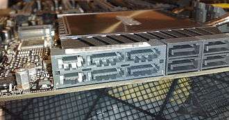
Cables, connectors, and ports
Connectors and cables present the most visible differences between SATA and parallel ATA drives. Unlike PATA, the same connectors are used on 3.5-inch (89 mm) SATA hard disks (for desktop and server computers) and 2.5-inch (64 mm) disks (for portable or small computers).[37]
Standard SATA connectors for both data and power have a conductor pitch of 1.27 mm (0.050 inches). Low insertion force is required to mate a SATA connector. A smaller mini-SATA or mSATA connector is used by smaller devices such as 1.8-inch SATA drives, some DVD and Blu-ray drives, and mini SSDs.[38]
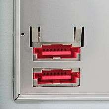
A special eSATA connector is specified for external devices, and an optionally implemented provision for clips to hold internal connectors firmly in place. SATA drives may be plugged into SAS controllers and communicate on the same physical cable as native SAS disks, but SATA controllers cannot handle SAS disks.
Female SATA ports (on motherboards for example) are for use with SATA data cables that have locks or clips to prevent accidental unplugging. Some SATA cables have right- or left-angled connectors to ease connection to circuit boards.
Data connector
| Pin # | Mating | Function | |
|---|---|---|---|
| 1 | 1st | Ground | |
| 2 | 2nd | A+ (transmit) | |
| 3 | 2nd | A− (transmit) | |
| 4 | 1st | Ground | |
| 5 | 2nd | B− (receive) | |
| 6 | 2nd | B+ (receive) | |
| 7 | 1st | Ground | |
| — | Coding notch | ||
The SATA standard defines a data cable with seven conductors (three grounds and four active data lines in two pairs) and 8 mm wide wafer connectors on each end. SATA cables can have lengths up to 1 metre (3.3 ft), and connect one motherboard socket to one hard drive. PATA ribbon cables, in comparison, connect one motherboard socket to one or two hard drives, carry either 40 or 80 wires, and are limited to 45 centimetres (18 in) in length by the PATA specification; however, cables up to 90 centimetres (35 in) are readily available. Thus, SATA connectors and cables are easier to fit in closed spaces, and reduce obstructions to air cooling. Although they are more susceptible to accidental unplugging and breakage than PATA, users can purchase cables that have a locking feature, whereby a small (usually metal) spring holds the plug in the socket.
SATA connectors may be straight, right-angled, or left angled. Angled connectors allow lower profile connections. Right-angled (also called 90 degree) connectors lead the cable immediately away from the drive, on the circuit board side. Left-angled (also called 270 degree) connectors lead the cable across the drive towards its top.
One of the problems associated with the transmission of data at high speed over electrical connections is described as noise, which is due to electrical coupling between data circuits and other circuits. As a result, the data circuits can both affect other circuits, and be affected by them. Designers use a number of techniques to reduce the undesirable effects of such unintentional coupling. One such technique used in SATA links is differential signaling. This is an enhancement over PATA, which uses single-ended signaling. The use of fully shielded twin-ax conductors, with multiple ground connections, for each differential pair improves isolation between the channels and reduces the chances of lost data in difficult electrical environments.
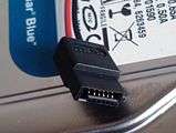
 A seven-pin SATA data cable (left-angled version of the connector)
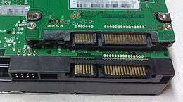
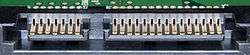 SATA connector on a 3.5-inch hard drive, with data pins on the left, and power pins on the right. The two different pin lengths ensure a specific mating order; the longer lengths are ground pins and make contact first.
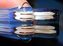 SATA 3.0 (6 Gbit/s) cable showing fully shielded twin-ax pairs
Power connectors
Standard connector
| Pin # | Mating | Function | |
|---|---|---|---|
| — | Coding notch | ||
| 1 | 3rd | 3.3 V | |
| 2 | 3rd | ||
| 3 | 2nd | ||
| 4 | 1st | Ground | |
| 5 | 2nd | ||
| 6 | 2nd | ||
| 7 | 2nd | 5 V | |
| 8 | 3rd | ||
| 9 | 3rd | ||
| 10 | 2nd | Ground | |
| 11 | 3rd | Staggered spinup/activity (in supporting drives) | |
| 12 | 1st | Ground | |
| 13 | 2nd | 12 V | |
| 14 | 3rd | ||
| 15 | 3rd | ||

SATA specifies a different power connector than the four-pin Molex connector used on Parallel ATA (PATA) devices (and earlier small storage devices, going back to ST-506 hard disk drives and even to floppy disk drives that predated the IBM PC). It is a wafer-type connector, like the SATA data connector, but much wider (fifteen pins versus seven) to avoid confusion between the two. Some early SATA drives included the four-pin Molex power connector together with the new fifteen-pin connector, but most SATA drives now have only the latter.
The new SATA power connector contains many more pins for several reasons:[40]
- 3.3 V is supplied along with the traditional 5 V and 12 V supplies. However, very few drives actually use it, so they may be powered from a four-pin Molex connector with an adapter.
- To reduce impedance and increase current capability, each voltage is supplied by three pins in parallel, though one pin in each group is intended for precharging (see below). Each pin should be able to carry 1.5 A.
- Five parallel pins provide a low-impedance ground connection.
- Two ground pins, and one pin for each supplied voltage, support hot-plug precharging. Ground pins 4 and 12 in a hot-swap cable are the longest, so they make contact first when the connectors are mated. Drive power connector pins 3, 7, and 13 are longer than the others, so they make contact next. The drive uses them to charge its internal bypass capacitors through current-limiting resistances. Finally, the remaining power pins make contact, bypassing the resistances and providing a low-impedance source of each voltage. This two-step mating process avoids glitches to other loads and possible arcing or erosion of the SATA power connector contacts.
- Pin 11 can function for staggered spinup, activity indication, both, or nothing. It is an open collector signal, that may be pulled down by the connector or the drive. If pulled down at the connector (as it is on most cable-style SATA power connectors), the drive spins up as soon as power is applied. If left floating, the drive waits until it is spoken to. This prevents many drives from spinning up simultaneously, which might draw too much power. The pin is also pulled low by the drive to indicate drive activity. This may be used to give feedback to the user through an LED.
Passive adapters are available that convert a four-pin Molex connector to a SATA power connector, providing the 5 V and 12 V lines available on the Molex connector, but not 3.3 V. There are also four-pin Molex-to-SATA power adapters that include electronics to additionally provide the 3.3 V power supply.[41] However, most drives do not require the 3.3 V power line.[42]
Slimline connector
| Pin # | Mating | Function | |
|---|---|---|---|
| — | Coding notch | ||
| 1 | 3rd | Device presence | |
| 2 | 2nd | 5 V | |
| 3 | 2nd | ||
| 4 | 2nd | Manufacturing diagnostic | |
| 5 | 1st | Ground | |
| 6 | 1st | ||
SATA 2.6 is the first revision that defined the slimline connector, intended for smaller form-factors such as notebook optical drives. Pin 1 of the slimline signal connector, denoting device presence, is shorter than the others to allow hot-swapping. The slimline signal connector is identical and compatible with the standard version, while the power connector is reduced to six pins so it supplies only +5 V, and not +12 V or +3.3 V.[43]
Low-cost adapters exist to convert from standard SATA to slimline SATA.
 A six-pin slimline SATA power connector
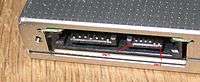 The back of a SATA-based slimline optical drive
Micro connector
| Pin # | Mating | Function | |
|---|---|---|---|
| 1 | 3rd | 3.3 V | |
| 2 | 2nd | ||
| 3 | 1st | Ground | |
| 4 | 1st | ||
| 5 | 2nd | 5 V | |
| 6 | 3rd | ||
| 7 | 3rd | Reserved | |
| — | Coding notch | ||
| 8 | 3rd | Vendor specific | |
| 9 | 2nd | ||

The micro SATA connector (sometimes called uSATA or μSATA[44]) originated with SATA 2.6, and is intended for 1.8-inch (46 mm) hard disk drives. There is also a micro data connector, similar in appearance but slightly thinner than the standard data connector.
eSATA

Standardized in 2004, eSATA (e standing for external) provides a variant of SATA meant for external connectivity. It uses a more robust connector, longer shielded cables, and stricter (but backward-compatible) electrical standards. The protocol and logical signaling (link/transport layers and above) are identical to internal SATA. The differences are:
- Minimum transmit amplitude increased: Range is 500–600 mV instead of 400–600 mV.
- Minimum receive amplitude decreased: Range is 240–600 mV instead of 325–600 mV.
- Maximum cable length increased to 2 metres (6.6 ft) (USB and FireWire allow longer distances.)
- The eSATA cable and connector is similar to the SATA 1.0a cable and connector, with these exceptions:
- The eSATA connector is mechanically different to prevent unshielded internal cables from being used externally. The eSATA connector discards the "L"-shaped key and changes the position and size of the guides.
- The eSATA insertion depth is deeper: 6.6 mm instead of 5 mm. The contact positions are also changed.
- The eSATA cable has an extra shield to reduce EMI to FCC and CE requirements. Internal cables do not need the extra shield to satisfy EMI requirements because they are inside a shielded case.
- The eSATA connector uses metal springs for shield contact and mechanical retention.
- The eSATA connector has a design-life of 5,000 matings; the ordinary SATA connector is only specified for 50.
Aimed at the consumer market, eSATA enters an external storage market served also by the USB and FireWire interfaces. The SATA interface has certain advantages. Most external hard-disk-drive cases with FireWire or USB interfaces use either PATA or SATA drives and "bridges" to translate between the drives' interfaces and the enclosures' external ports; this bridging incurs some inefficiency. Some single disks can transfer 157 MB/s during real use,[17] about four times the maximum transfer rate of USB 2.0 or FireWire 400 (IEEE 1394a) and almost twice as fast as the maximum transfer rate of FireWire 800. The S3200 FireWire 1394b specification reaches around 400 MB/s (3.2 Gbit/s), and USB 3.0 has a nominal speed of 5 Gbit/s. Some low-level drive features, such as S.M.A.R.T., may not operate through some USB[45] or FireWire or USB+FireWire bridges; eSATA does not suffer from these issues provided that the controller manufacturer (and its drivers) presents eSATA drives as ATA devices, rather than as SCSI devices, as has been common with Silicon Image, JMicron, and NVIDIA nForce drivers for Windows Vista. In those cases SATA drives do not have low-level features accessible.
The eSATA version of SATA 6G operates at 6.0 Gbit/s (the term "SATA III" is avoided by the SATA-IO organization to prevent confusion with SATA II 3.0 Gbit/s, which was colloquially referred to as "SATA 3G" [bit/s] or "SATA 300" [MB/s] since the 1.5 Gbit/s SATA I and 1.5 Gbit/s SATA II were referred to as both "SATA 1.5G" [bit/s] or "SATA 150" [MB/s]).
Therefore, eSATA connections operate with negligible differences between them.[46] Once an interface can transfer data as fast as a drive can handle them, increasing the interface speed does not improve data transfer. Most newer computers, including netbooks/laptops, have external SATA (eSATA) connectors, in addition to USB 2.0 and sometimes USB 3.0 ports, though relatively few have built-in FireWire ports.
There are some disadvantages, however, to the eSATA interface:
- Devices built before the eSATA interface became popular lack external SATA connectors.
- For small form-factor devices (such as external 2.5-inch (64 mm) disks), a PC-hosted USB or FireWire link can usually supply sufficient power to operate the device. However, eSATA connectors cannot supply power, and require a power supply for the external device. The related eSATAp (but mechanically incompatible, sometimes called eSATA/USB) connector adds power to an external SATA connection, so that an additional power supply is not needed.[47]
Desktop computers without a built-in eSATA interface can install an eSATA host bus adapter (HBA); if the motherboard supports SATA, an externally available eSATA connector can be added. Notebook computers can be upgraded with Cardbus[48] or ExpressCard[49] versions of an eSATA HBA. With passive adapters, the maximum cable length is reduced to 1 metre (3.3 ft) due to the absence of compliant eSATA signal-levels.
eSATAp
eSATAp stands for powered eSATA. It is also known as Power over eSATA, Power eSATA, eSATA/USB Combo, or eSATA USB Hybrid Port (EUHP). An eSATAp port combines the four pins of the USB 2.0 (or earlier) port, the seven pins of the eSATA port, and optionally two 12 V power pins.[50] Both SATA traffic and device power are integrated in a single cable, as is the case with USB but not eSATA. The 5 V power is provided through two USB pins, while the 12 V power may optionally be provided. Typically desktop, but not notebook, computers provide 12 V power, so can power devices requiring this voltage, typically 3.5-inch disk and CD/DVD drives, in addition to 5 V devices such as 2.5-inch drives.
Both USB and eSATA devices can be used with an eSATAp port, when plugged in with a USB or eSATA cable, respectively. An eSATA device cannot be powered via an eSATAp cable, but cables are available which make available both SATA or eSATA and power connectors from an eSATAp port.
An eSATAp connector can be built into a computer with internal SATA and USB, by fitting a bracket with connections for internal SATA, USB, and power connectors and an externally accessible eSATAp port. Though eSATAp connectors have been built into several devices, manufacturers do not refer to an official standard.
Pre-standard implementations
- Prior to the final eSATA 3 Gbit/s specification, a number of products were designed for external connection of SATA drives. Some of these use the internal SATA connector, or even connectors designed for other interface specifications, such as FireWire. These products are not eSATA compliant. The final eSATA specification features a specific connector designed for rough handling, similar to the regular SATA connector, but with reinforcements in both the male and female sides, inspired by the USB connector. eSATA resists inadvertent unplugging, and can withstand yanking or wiggling, which could break a male SATA connector (the hard-drive or host adapter, usually fitted inside the computer). With an eSATA connector, considerably more force is needed to damage the connector—and if it does break, it is likely to be the female side, on the cable itself, which is relatively easy to replace.
- Prior to the final eSATA 6 Gbit/s specification many add-on cards and some motherboards advertised eSATA 6 Gbit/s support because they had 6 Gbit/s SATA 3.0 controllers for internal-only solutions. Those implementations are non-standard, and eSATA 6 Gbit/s requirements were ratified in the July 18, 2011 SATA 3.1 specification.[51] Some products might not be fully eSATA 6 Gbit/s compliant.
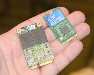
Mini-SATA (mSATA)
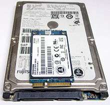
Mini-SATA (abbreviated as mSATA), which is distinct from the micro connector,[44] was announced by the Serial ATA International Organization on September 21, 2009.[52] Applications include netbooks, laptops and other devices that require a solid-state drive in a small footprint.
The connector is similar in appearance to a PCI Express Mini Card interface,[53] but is not electrically compatible; the data signals (TX±/RX± SATA, PETn0 PETp0 PERn0 PERp0 PCI Express) need a connection to the SATA host controller instead of the PCI Express host controller.
SFF-8784 connector
| Bottom | Top | ||||||
|---|---|---|---|---|---|---|---|
| Pin | Function | Pin | Function | Pin | Function | Pin | Function |
| 1 | Ground | 6 | Unused | 11 | Ground | 16 | +5 V |
| 2 | Ground | 7 | +5 V | 12 | B+ (transmit) | 17 | Ground |
| 3 | Ground | 8 | Unused | 13 | B− (transmit) | 18 | A− (receive) |
| 4 | Ground[lower-alpha 4] | 9 | Unused | 14 | Ground | 19 | A+ (receive) |
| 5 | LED | 10 | Ground | 15 | +5 V | 20 | Ground |
Slim 2.5-inch SATA devices, 5 mm (0.20 inches) in height, use the twenty-pin SFF-8784 edge connector to save space. By combining the data signals and power lines into a slim connector that effectively enables direct connection to the device's printed circuit board (PCB) without additional space-consuming connectors, SFF-8784 allows further internal layout compaction for portable devices such as ultrabooks.[54]
Pins 1 to 10 are on the connector's bottom side, while pins 11 to 20 are on the top side.[54]
SATA Express
SATA Express, initially standardized in the SATA 3.2 specification,[55] is an interface that supports either SATA or PCI Express storage devices. The host connector is backward compatible with the standard 3.5-inch SATA data connector, allowing up to two legacy SATA devices to be connected.[56] At the same time, the host connector provides up to two PCI Express 3.0 lanes as a pure PCI Express connection to the storage device, allowing bandwidths of up to 2 GB/s.[28][57]
Instead of the otherwise usual approach of doubling the native speed of the SATA interface, PCI Express was selected for achieving data transfer speeds greater than 6 Gbit/s. It was concluded that doubling the native SATA speed would take too much time, too many changes would be required to the SATA standard, and would result in a much greater power consumption when compared to the existing PCI Express bus.[58]
In addition to supporting legacy Advanced Host Controller Interface (AHCI), SATA Express also makes it possible for NVM Express (NVMe) to be used as the logical device interface for connected PCI Express storage devices.[59]
M.2 (NGFF)
M.2, formerly known as the Next Generation Form Factor (NGFF), is a specification for computer expansion cards and associated connectors. It replaces the mSATA standard, which uses the PCI Express Mini Card physical layout. Having a smaller and more flexible physical specification, together with more advanced features, the M.2 is more suitable for solid-state storage applications in general, especially when used in small devices like ultrabooks or tablets.[60]
The M.2 standard is designed as a revision and improvement to the mSATA standard, allowing for larger printed circuit boards (PCBs) to be manufactured. While mSATA took advantage of the existing PCI Express Mini Card form factor and connector, M.2 has been designed to maximize usage of the card space, while minimizing the footprint.[60][61][62]
Supported host controller interfaces and internally provided ports are a superset to those defined by the SATA Express interface. Essentially, the M.2 standard is a small form factor implementation of the SATA Express interface, with the addition of an internal USB 3.0 port.[60]
U.2 (SFF-8639)
U.2, formerly known as SFF-8639. Like its predecessor it carries a PCI Express electrical signal, however U.2 uses a PCIe 3.0 ×4 link providing a higher bandwidth of 32 Gbit/s in each direction.
Protocol
The SATA specification defines three distinct protocol layers: physical, link, and transport.
Physical layer
The physical layer defines SATA's electrical and physical characteristics (such as cable dimensions and parasitics, driver voltage level and receiver operating range), as well as the physical coding subsystem (bit-level encoding, device detection on the wire, and link initialization).
Physical transmission uses differential signaling. The SATA PHY contains a transmit pair and receive pair. When the SATA-link is not in use (example: no device attached), the transmitter allows the transmit pins to float to their common-mode voltage level. When the SATA-link is either active or in the link-initialization phase, the transmitter drives the transmit pins at the specified differential voltage (1.5 V in SATA/I).
SATA physical coding uses a line encoding system known as 8b/10b encoding. This scheme serves multiple functions required to sustain a differential serial link. First, the stream contains necessary synchronization information that allows the SATA host/drive to extract clocking. The 8b/10b encoded sequence embeds periodic edge transitions to allow the receiver to achieve bit-alignment without the use of a separately transmitted reference clock waveform. The sequence also maintains a neutral (DC-balanced) bitstream, which allows the transmit drivers and receiver inputs to be AC-coupled. Generally, the actual SATA signalling is half-duplex, meaning that it can only read or write data at any one time.
Also, SATA uses some of the special characters defined in 8b/10b. In particular, the PHY layer uses the comma (K28.5) character to maintain symbol-alignment. A specific four-symbol sequence, the ALIGN primitive, is used for clock rate-matching between the two devices on the link. Other special symbols communicate flow control information produced and consumed in the higher layers (link and transport).
Separate point-to-point AC-coupled low-voltage differential signaling (LVDS) links are used for physical transmission between host and drive.
The PHY layer is responsible for detecting the other SATA/device on a cable, and link initialization. During the link-initialization process, the PHY is responsible for locally generating special out-of-band signals by switching the transmitter between electrical-idle and specific 10b-characters in a defined pattern, negotiating a mutually supported signalling rate (1.5, 3.0, or 6.0 Gbit/s), and finally synchronizing to the far-end device's PHY-layer data stream. During this time, no data is sent from the link-layer.
Once link-initialization has completed, the link-layer takes over data-transmission, with the PHY providing only the 8b/10b conversion before bit transmission.
Link layer
After the PHY-layer has established a link, the link layer is responsible for transmission and reception of Frame Information Structures (FISs) over the SATA link. FISs are packets containing control information or payload data. Each packet contains a header (identifying its type), and payload whose contents are dependent on the type. The link layer also manages flow control over the link.
Transport layer
Layer number three in the serial ATA specification is the transport layer. This layer has the responsibility of acting on the frames and transmitting/receiving the frames in an appropriate sequence. The transport layer handles the assembly and disassembly of FIS structures, which includes, for example, extracting content from register FISs into the task-file and informing the command layer. In an abstract fashion, the transport layer is responsible for creating and encoding FIS structures requested by the command layer, and removing those structures when the frames are received.
When DMA data is to be transmitted and is received from the higher command layer, the transport layer appends the FIS control header to the payload, and informs the link layer to prepare for transmission. The same procedure is performed when data is received, but in reverse order. The link layer signals to the transport layer that there is incoming data available. Once the data is processed by the link layer, the transport layer inspects the FIS header and removes it before forwarding the data to the command layer.
Topology

SATA uses a point-to-point architecture. The physical connection between a controller and a storage device is not shared among other controllers and storage devices. SATA defines multipliers, which allows a single SATA controller port to drive up to fifteen storage devices. The multiplier performs the function of a hub; the controller and each storage device is connected to the hub.[63] This is conceptually similar to SAS expanders.
Modern PC systems have SATA controllers built into the motherboard, typically featuring two to eight ports. Additional ports can be installed through add-in SATA host adapters (available in variety of bus-interfaces: USB, PCI, PCIe).
Backward and forward compatibility
SATA and PATA
At the device level, SATA and PATA (Parallel AT Attachment) devices remain completely incompatible—they cannot be interconnected. At the application level, SATA devices can be specified to look and act like PATA devices.[64] Many motherboards offer a "legacy mode" option, which makes SATA drives appear to the OS like PATA drives on a standard controller. This eases OS installation by not requiring a specific driver to be loaded during setup but sacrifices support for some features of SATA and, in general, disables some of the boards' PATA or SATA ports, since the standard PATA controller interface supports only four drives. (Often, which ports are disabled is configurable.)
The common heritage of the ATA command set has enabled the proliferation of low-cost PATA to SATA bridge-chips. Bridge-chips were widely used on PATA drives (before the completion of native SATA drives) as well as standalone "dongles."[65] When attached to a PATA drive, a device-side dongle allows the PATA drive to function as a SATA drive. Host-side dongles allow a motherboard PATA port to function as a SATA host port.
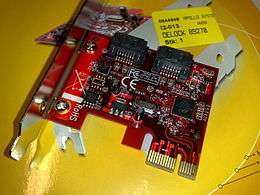
The market has produced powered enclosures for both PATA and SATA drives that interface to the PC through USB, Firewire or eSATA, with the restrictions noted above. PCI cards with a SATA connector exist that allow SATA drives to connect to legacy systems without SATA connectors.
SATA 1.5 Gbit/s and SATA 3 Gbit/s
The designers of SATA aimed for backward and forward compatibility with future revisions of the SATA standard. To prevent interoperability problems that could occur when next generation SATA drives are installed on motherboards with standard legacy SATA 1.5 Gbit/s host controllers, many manufacturers have made it easy to switch those newer drives to the previous standard's mode. For example, Seagate/Maxtor has added a user-accessible jumper-switch, known as the force 150, to enable the drive switch between forced 1.5 Gbit/s and 1.5/3 Gbit/s negotiated operation. Western Digital uses a jumper setting called OPT1 enabled to force 1.5 Gbit/s data transfer speed (OPT1 is enabled by putting the jumper on pins 5 and 6). Samsung drives can be forced to 1.5 Gbit/s mode using software that may be downloaded from the manufacturer's website. Configuring some Samsung drives in this manner requires the temporary use of a SATA-2 (SATA 3.0 Gbit/s) controller while programming the drive.
The force 150 switch (or equivalent) is also useful for attaching SATA 3 Gbit/s hard drives to SATA controllers on PCI cards, since many of these controllers (such as the Silicon Image chips) run at 3 Gbit/s, even though the PCI bus cannot reach 1.5 Gbit/s speeds. This can cause data corruption in operating systems that do not specifically test for this condition and limit the disk transfer speed.
SATA 3 Gbit/s and SATA 6 Gbit/s
SATA 3 Gbit/s and SATA 6 Gbit/s are compatible with each other. Most devices which are only SATA 3 Gbit/s can connect with devices that are SATA 6 Gbit/s, and vice versa, though SATA 3 Gbit/s devices only connect with SATA 6 Gbit/s devices at the slower 3 Gbit/s speed.
SATA 1.5 Gbit/s and SATA 6 Gbit/s
SATA 1.5 Gbit/s and SATA 6 Gbit/s are compatible with each other. Most devices which are only SATA 1.5 Gbit/s can connect with devices that are SATA 6 Gbit/s, and vice versa, though SATA 1.5 Gbit/s devices only connect with SATA 6 Gbit/s devices at the slower 1.5 Gbit/s speed.
Comparison to other interfaces
SATA and SCSI
Parallel SCSI uses a more complex bus than SATA, usually resulting in higher manufacturing costs. SCSI buses also allow connection of several drives on one shared channel, whereas SATA allows one drive per channel, unless using a port multiplier. Serial Attached SCSI uses the same physical interconnects as SATA, and most SAS HBAs also support 3 and 6 Gbit/s SATA devices (an HBA requires support for Serial ATA Tunneling Protocol).
SATA 3 Gbit/s theoretically offers a maximum bandwidth of 300 MB/s per device which is only slightly lower than the rated speed for SCSI Ultra 320 with a maximum of 320 MB/s in total for all devices on a bus.[66] SCSI drives provide greater sustained throughput than multiple SATA drives connected via a simple (i.e., command-based) port multiplier because of disconnect-reconnect and aggregating performance.[67] In general, SATA devices link compatibly to SAS enclosures and adapters, whereas SCSI devices cannot be directly connected to a SATA bus.
SCSI, SAS, and fibre-channel (FC) drives are more expensive than SATA, so they are used in servers and disk arrays where the better performance justifies the additional cost. Inexpensive ATA and SATA drives evolved in the home-computer market, hence there is a view that they are less reliable. As those two worlds overlapped, the subject of reliability became somewhat controversial. Note that, in general, the failure rate of a disk drive is related to the quality of its heads, platters and supporting manufacturing processes, not to its interface.
Use of serial ATA in the business market increased from 22% in 2006 to 28% in 2008.[68]
Comparison with other buses
SCSI-3 devices with SCA-2 connectors are designed for hot swapping. Many server and RAID systems provide hardware support for transparent hot swapping. The designers of the SCSI standard prior to SCA-2 connectors did not target hot swapping, but in practice, most RAID implementations support hot swapping of hard disks.
| Name | Raw data rate | Data rate | Max. cable length | Power provided | Devices per channel |
|---|---|---|---|---|---|
| eSATA | 6 Gbit/s | 600 MB/s |
|
No | 1 (15 with a port multiplier) |
| eSATAp | 3 Gbit/s | 300 MB/s | 5 V, and, optionally, 12 V[69] | ||
| SATA revision 3.2 | 16 Gbit/s | 1.97 GB/s[lower-alpha 5] | 1 m | No | |
| SATA revision 3.0 | 6 Gbit/s | 600 MB/s[70] | |||
| SATA revision 2.0 | 3 Gbit/s | 300 MB/s | |||
| SATA revision 1.0 | 1.5 Gbit/s | 150 MB/s[71] | 1 | ||
| PATA (IDE) 133 | 1.064 Gbit/s | 133.3 MB/s[lower-alpha 6] | 0.46 m (18 in) | 5 V (only 2.5-inch drive 44-pin connector) | 2 |
| SAS-3 | 12 Gbit/s | 1.2 GB/s | 10 m | Backplane connectors only | 1 (> 65k with expanders) |
| SAS-2 | 6 Gbit/s | 600 MB/s | |||
| SAS-1 | 3 Gbit/s | 300 MB/s | |||
| IEEE 1394 (FireWire) 3200 | 3.144 Gbit/s | 393 MB/s | 100 m (more with special cables) | 15 W, 12–25 V | 63 (with a hub) |
| IEEE 1394 (FireWire) 800 | 786 Mbit/s | 98.25 MB/s | 100 m[72] | ||
| IEEE 1394 (FireWire) 400 | 393 Mbit/s | 49.13 MB/s | 4.5 m[72][73] | ||
| USB 3.1 | 10 Gbit/s | 1.21 GB/s[lower-alpha 7] | 3 m[74] | 100 W, 5, 12 or 20 V[75] | 127 (with a hub)[74] |
| USB 3.0[lower-alpha 8] | 5 Gbit/s | 400 MB/s or more (excl. protocol overhead, flow control, and framing)[76] |
4.5 W, 5 V | ||
| USB 2.0 | 480 Mbit/s | 35 MB/s | 5 m[77] | 2.5 W, 5 V | |
| USB 1.1 | 12 Mbit/s | 1.5 MB/s | 3 m | Yes | |
| SCSI Ultra-320 | 2.56 Gbit/s | 320 MB/s | 12 m | Backplane connector only | 15 excl. host bus adapter/host |
| 10GFC Fibre Channel | 10.52 Gbit/s | 1.195 GB/s | 2 m – 50 km | No | 126 (16,777,216 with switches) |
| 4GFC Fibre Channel | 4.25 Gbit/s | 398 MB/s | 12 m | ||
| InfiniBand Quad Rate |
10 Gbit/s | 0.98 GB/s | 1 with point-to-point, many with switched fabric | ||
| Thunderbolt | 1.22 GB/s |
|
10 W (only copper) | 7 | |
| Thunderbolt 2 | 20 Gbit/s | 2.44 GB/s | |||
| Thunderbolt 3 | 40 Gbit/s | 4.88 GB/s | 100 W (only copper) |
See also
- FATA (hard disk drive)
- libATA
- List of device bit rates
- Parallel ATA (PATA)
- Serial attached SCSI (SAS)
Notes
- ↑ AT Attachment (ATA) interface was initially developed as Integrated Drive Electronics (IDE) for use in early PC AT equipment. With the introduction of SATA, the AT Attachment interface was renamed to Parallel ATA (PATA).
- ↑ Integrated Drive Electronics
- ↑ Disk-based memory (hard drives), solid state disk devices such as USB drives, DVD-based storage, bit rates, bus speeds, and network speeds, are specified using decimal meanings for K (10001), M (10002), G (10003), ...
- ↑ Drive present
- ↑ 16 Gbit/s raw bit rate, with 128b/130b encoding
- ↑ 15 ns cycles, 16-bit transfers
- ↑ 10 Gbit/s raw bit rate, with 128b/132b encoding
- ↑ USB 3.0 specification was released to hardware vendors on 17 November 2008.
References
- 1 2 "Software status - ata Wiki". ata.wiki.kernel.org. 2008-08-17. Archived from the original on 2009-01-24. Retrieved 2010-01-26.
- 1 2 "Serial ATA: High Speed Serialized AT Attachment" (PDF). www.serialata.org. Serial ATA Working Group. January 7, 2003. Retrieved 2016-02-21.
- 1 2 "1991 IAS Total Data Management" (PDF). www.coreinternational.info. Core International. Retrieved 2016-11-18.
- ↑ "Lamars, Lawrence J., Information technology - AT Attachment Interface for Disk Drives, Computer and Business Equipment Manufacturers Association, 1994, xi (introduction)" (PDF). Retrieved 2016-08-02.
- ↑ "Govindarajalu,B., IBM PC And Clones: Hardware, Troubleshooting And Maintenance, Tata McGraw-Hill publishing Company, 2002, pg. xxxi". Amazon.com. Retrieved 2016-08-02.
- ↑ "Serial ATA: Meeting Storage Needs Today and Tomorrow" (PDF). Retrieved 2011-10-30.
- ↑ Donald Melanson (2008-02-25). "CFast CompactFlash cards now said to be coming in "18 to 24 months"". Engadget. Retrieved 2009-03-19.
- ↑ "Pretec release CFast card with SATA interface". DPReview. 8 January 2009. Retrieved 19 March 2009.
- ↑ "Registered Trademark Hot Plug". www.uspto.gov/. USPTO. Retrieved 2016-11-18.
- ↑ "Patent Application in USA: Disc interface circuit". uspto.gov. USPTO. Retrieved 2016-11-18.
- ↑ "Patent Application in Europe: Disc interface circuit". register.epo.org. European Patent Organisation. Retrieved 2016-11-18.
- ↑ "1990 Ad for CPR Series" (PDF). www.coreinternational.info. Core International. Retrieved 2016-11-18.
- ↑ "Serial ATA (SATA) Linux hardware/driver status report". linux-ata.org. Archived from the original on 2007-03-12. Retrieved 2010-01-26.
- ↑ Intel Matrix Storage Technology - Unattended Installation Instructions Under Windows* XP
- ↑ http://kb.sandisk.com/app/answers/detail/a_id/8142/~/difference-between-sata-i,-sata-ii-and-sata-iii www.sandisk.com. Sandisk. Retrieved April 2016
- ↑ Geoff Gasior (2004-03-08). "Western Digital's Raptor WD740GD SATA hard drive: Single-user performance, multi-user potential". techreport.com. Retrieved 2015-06-16.
- 1 2 Patrick Schmid and Achim Roos (2010-04-06). "VelociRaptor Returns: 6Gbit/s, 600GB, And 10,000 RPM". tomshardware.com. Retrieved 2010-06-26.
- 1 2 "SATA-IO Specifications and Naming Conventions". sata-io.org. Retrieved 2012-08-30.
- ↑ "New SATA Spec Will Double Data Transfer Rates to 6 Gbit/s" (PDF) (Press release). SATA-IO. 2008-08-18. Retrieved 2009-07-13.
- ↑ "SATA Revision 3.0". SATA-IO. 27 May 2009. Retrieved 4 December 2009.
- ↑ "SATA-IO Releases SATA Revision 3.0 Specification" (PDF) (Press release). Serial ATA International Organization. May 27, 2009. Retrieved 3 July 2009.
- ↑ Rick Merritt (2008-08-18). "Serial ATA doubles data rate to 6 Gbit/s (EETimes news report)". eetimes.com. Archived from the original on 2012-10-27. Retrieved 2010-01-26.
- ↑ "SATA-IO Releases Revision 3.1 Specification" (PDF). SATA-IO. 2011-07-18. Retrieved 2013-07-22.
- ↑ Hilbert Hagedoorn (2011-07-20). "SATA 3.1 specifications have been published". guru3d.com. Retrieved 2012-09-26.
- ↑ "Msata Faq". forum.notebookreview.com. Retrieved 2011-10-30.
- ↑ "Serial ATA International Organization: SATA Universal Storage Module (USM)". sata-io.org. Retrieved 2011-10-30.
- ↑ Perenson, Melissa J. "New Universal Storage Module Promises to Evolve Portable Data". PCWorld. Retrieved 2014-02-12.
- 1 2 "SATA-IO Unveils Revision 3.2 Specification" (PDF). SATA-IO. 2013-08-08. Retrieved 2015-09-11.
- ↑ Enabling Higher Speed Storage Applications with SATA Express, Serial ATA International Organization.
- ↑ SATA-IO announces 16Gb/s SATA 3.2 specification
- ↑ "SATA M.2 Card". SATA-IO. Retrieved 2014-01-16.
- ↑ SATA µSSD, Serial ATA International Organization.
- ↑ "SATA-IO Rolls Out USM Slim Specification for Thinner, Lighter External Storage" (PDF). SATA-IO. Retrieved 2014-02-12.
- ↑ "SATA Enables Life Unplugged". SATA-IO. Retrieved 2014-01-16.
- ↑ "SATA-IO FAQ" (PDF). What else is new in SATA specification v3.2?. SATA-IO. p. 2. Retrieved 2013-10-03.
- ↑ First specifications leaked from SATA-IO, Serial ATA International Organization, GuruHT.com
- ↑ "Can I install a laptop 2.5" SATA drive on a desktop without any adapters?". superuser.com. 2009. Retrieved 2013-12-04.
- ↑ "Get ready for mini-SATA". The Tech Report. 2009-09-21. Retrieved 2010-01-26.
- ↑ "Serial ATA (SATA) pinout diagram". pinoutsguide.com. 2013-12-16. Retrieved 2014-04-02.
- ↑ "Serial ATA (SATA, Serial Advanced Technology Attachment)". allpinouts.org. Archived from the original on 2008-11-08. Retrieved 2016-07-05.
- ↑ Example of active power adapter
- ↑ "Serial ATA (SATA) power connector pinout and connections @". pinouts.ru. 2013-05-31. Retrieved 2013-06-14.
- ↑ "Serial ATA Revision 2.6" (PDF). Serial ATA International Organization. p. 115.
- 1 2 "Understand the difference: micro-SATA vs. mSATA". amazon.com. 2013-02-23. Archived from the original on 2013-08-02. Retrieved 2013-11-06.
- ↑ "USB – smartmontools". sourceforge.net. Retrieved 2012-01-13.
- ↑ "Questions about the indicators of health/performance (in percent)". hddlife.com. Retrieved 2007-08-29.
- ↑ "External Serial ATA" (PDF). Silicon Image, Inc. Retrieved 8 August 2009.
- ↑ "CardBus SATA adapter". addonics.com. Retrieved 2010-01-26.
- ↑ "ExpressCard SATA adapter". addonics.com. Retrieved 2010-01-26.
- ↑ "Addonics Technology: Hybrid eSATA (eSATA USB hybrid) interface". addonics.com. Retrieved 2011-10-30.
- ↑ "Frequently Asked Questions About SATA 6 Gbit/s and the SATA Revision 3.0 Specification" (PDF). May–June 2009. Retrieved 2011-10-30.
- ↑ "mSATA Press Release" (PDF). Retrieved 11 March 2011.
- ↑ "Intel 310 SSD" (PDF). Intel. Archived from the original (PDF) on 12 January 2011. Retrieved 11 March 2011.
- 1 2 3 "SFF-8784 Edge Connector Pin Definitions: Information Sheet" (PDF). Western Digital. 2013. Retrieved February 26, 2015.
- ↑ "SATA Revision 3.2". SATA-IO. Retrieved 2013-10-02.
- ↑ "Connector Mating Matrix" (PDF). SATA-IO. Retrieved 2013-10-02.
- ↑ "Enabling Higher Speed Storage Applications with SATA Express". SATA-IO. 2013. Retrieved 2013-10-02.
- ↑ Paul Wassenberg (2013-06-25). "SATA Express: PCIe Client Storage" (PDF). SATA-IO. Retrieved 2013-10-02.
- ↑ Dave Landsman. "AHCI and NVMe as Interfaces for SATA Express Devices – Overview" (PDF). SanDisk. Retrieved 2013-10-02.
- 1 2 3 "SATA M.2 Card". SATA-IO. Retrieved 2013-09-14.
- ↑ "Intel SSD 530 Series Arriving Next Week – Feature NGFF M.2 Interface". WCCF Tech. Retrieved 2013-09-14.
- ↑ "M.2 (NGFF) Quick Reference Guide" (PDF). Tyco Electronics. Retrieved 2013-11-16.
- ↑ "Port Multipliers". SATA-IO. Retrieved 2014-02-17.
- ↑ "A comparison with Ultra ATA Technology" (PDF). SATA-IO. Archived from the original (PDF) on 2012-03-27. Retrieved 2014-08-15.
- ↑ "Image of PATA to SATA "dongle."". Retrieved 2011-10-30.
- ↑ Ultra-640 is specified, but devices do not exist
- ↑ FIS-based switching is comparable to SCSI's tagged command queueing
- ↑ "Serial ATA: Meeting Storage Needs Today and Tomorrow" (PDF). SATA-IO. Archived from the original (PDF) on 17 April 2012. Retrieved 26 March 2016.
- ↑ "eSATAp Application". delock.de. Retrieved 2010-01-26.
- ↑ "Fast Just Got Faster: SATA 6Gbit/s" (PDF). sata-io.org. May 27, 2009. Archived from the original (PDF) on November 26, 2012. Retrieved 2011-10-25.
- ↑ "Designing Serial ATA For Today's Applications and Tomorrow's Storage Needs" (PDF). sata-io.org. Retrieved 2011-10-25.
- 1 2 "FireWire Developer Note: FireWire Concepts". Apple Developer Connection. Retrieved 2009-07-13.
- ↑ 16 cables can be daisy chained up to 72 m
- 1 2 Frenzel, Louis E. (September 25, 2008). "USB 3.0 Protocol Analyzer Jumpstarts 4.8-Gbit/s I/O Projects". Electronic Design. Retrieved 2009-07-03.
- ↑ Howse, Brett (September 17, 2014). "USB Power Delivery v2.0 Specification Finalized - USB Gains Alternate Modes". AnandTech. Retrieved 2015-01-15.
- ↑ Universal Serial Bus Specification Revision 3.0. 20 December 2012. p. 75 (4–4.11). Archived from the original on 2011-05-14. Retrieved 14 April 2011.
- ↑ USB hubs can be daisy chained up to 25 m
- ↑ Minich, Makia (25 June 2007). "Infiniband Based Cable Comparison". Archived from the original (PDF) on 2012-02-10. Retrieved 11 February 2008.
- ↑ Feldman, Michael (17 July 2007). "Optical Cables Light Up InfiniBand". HPCwire. Tabor Publications & Events. p. 1. Retrieved 2008-02-11.
External links
| Wikimedia Commons has media related to: |
- Serial ATA International Organization (SATA-IO)
- EETimes Serial ATA and the evolution in data storage technology, Mohamed A. Salem
- "SATA-1" specification, as a zipped pdf; Serial ATA: High Speed Serialized AT Attachment, Revision 1.0a, 7-January-2003.
- Errata and Engineering Change Notices to above "SATA-1" specification, as a zip of pdfs
- Dispelling the Confusion: SATA II does not mean 3 Gbit/s
- "External Serial ATA – White Paper" (PDF). SATA-IO. 515 kB – on eSATA
- SATA motherboard connector pinout
- "Serial ATA (SATA, Serial Advanced Technology Attachment) Connector Pinout". allpinouts.org. Archived from the original on 2016-04-18.
- Serial ATA server and storage use cases
- How to Install and Troubleshoot SATA Hard Drives
- Serial ATA and the 7 Deadly Sins of Parallel ATA
- Everything You Need to Know About Serial ATA
- Barracuda XT - the first SATA 6Gbit/s HDD
- Mini-FAQ on SATA II (specifications/performance/compatibility)
- USB 3.0 vs. eSATA: Is faster better?
- Universal ATA driver for Windows NT3.51/NT4/2000/XP/2003/Vista/7/ReactOS: With PATA/SATA/AHCI support – a universal, free and open-source ATA driver with PATA/SATA support
- Adapter or converter for a SATA drive to become a PATA drive
- Adapter or converter for either: (1) a PATA drive to become a SATA drive; or (2) a PATA port on the motherboard of a desktop computer to become a SATA port
| General | |
|---|---|
| Standards |
|
| Storage | |
| Peripheral | |
| Audio | |
| Portable | |
| Embedded | |
Interfaces are listed by their speed in the (roughly) ascending order, so the interface at the end of each section should be the fastest. | |
| Key terminology | |||||||
|---|---|---|---|---|---|---|---|
| Flash manufacturers | |||||||
| Controllers |
| ||||||
| SSD manufacturers | |||||||
| Interfaces |
| ||||||
| Configurations | |||||||
| Related organizations | |||||||
| |||||||