Confocal microscopy
| Confocal microscopy | |
|---|---|
| Diagnostics | |
| MeSH | D018613 |
| OPS-301 code | 3-301 |


Confocal microscopy, most frequently confocal laser scanning microscopy (CLSM), is an optical imaging technique for increasing optical resolution and contrast of a micrograph by means of adding a spatial pinhole placed at the confocal plane of the lens to eliminate out-of-focus light.[1] It enables the reconstruction of three-dimensional structures from the obtained images by collecting sets of images at different depths (a process known as optical sectioning) within a thick object. This technique has gained popularity in the scientific and industrial communities and typical applications are in life sciences, semiconductor inspection and materials science.
A conventional microscope "sees" as far into the specimen as the light can penetrate, while a confocal microscope only "sees" images one depth level at a time. In effect, the CLSM achieves a controlled and highly limited depth of focus.
Basic concept

In the western world the principle of confocal imaging was patented in 1957 by Marvin Minsky[2][3] and aims to overcome some limitations of traditional wide-field fluorescence microscopes. In a conventional (i.e., wide-field) fluorescence microscope, the entire specimen is flooded evenly in light from a light source. All parts of the specimen in the optical path are excited at the same time and the resulting fluorescence is detected by the microscope's photodetector or camera including a large unfocused background part. In contrast, a confocal microscope uses point illumination (see Point Spread Function) and a pinhole in an optically conjugate plane in front of the detector to eliminate out-of-focus signal - the name "confocal" stems from this configuration. As only light produced by fluorescence very close to the focal plane can be detected, the image's optical resolution, particularly in the sample depth direction, is much better than that of wide-field microscopes. However, as much of the light from sample fluorescence is blocked at the pinhole, this increased resolution is at the cost of decreased signal intensity – so long exposures are often required. To offset this drop in signal after the pinhole, the light intensity is detected by a sensitive detector, usually a photomultiplier tube (PMT) or avalanche photodiode, transforming the light signal into an electrical one that is recorded by a computer.[4]
As only one point in the sample is illuminated at a time, 2D or 3D imaging requires scanning over a regular raster (i.e., a rectangular pattern of parallel scanning lines) in the specimen. The beam is scanned across the sample in the horizontal plane by using one or more (servo controlled) oscillating mirrors. This scanning method usually has a low reaction latency and the scan speed can be varied. Slower scans provide a better signal-to-noise ratio, resulting in better contrast and higher resolution.
The achievable thickness of the focal plane is defined mostly by the wavelength of the used light divided by the numerical aperture of the objective lens, but also by the optical properties of the specimen. The thin optical sectioning possible makes these types of microscopes particularly good at 3D imaging and surface profiling of samples.
Successive slices make up a 'z-stack' which can either be processed by certain software to create a 3D image, or it is merged into a 2D stack (predominately the maximum pixel intensity is taken, other common methods include using the standard deviation or summing the pixels).[1]
Confocal microscopy provides the capacity for direct, noninvasive, serial optical sectioning of intact, thick, living specimens with a minimum of sample preparation as well as a marginal improvement in lateral resolution.[4] Biological samples are often treated with fluorescent dyes to make selected objects visible. However, the actual dye concentration can be low to minimize the disturbance of biological systems: some instruments can track single fluorescent molecules. Also, transgenic techniques can create organisms that produce their own fluorescent chimeric molecules (such as a fusion of GFP, green fluorescent protein with the protein of interest).
Techniques used for horizontal scanning
Four types of confocal microscopes are commercially available: Confocal laser scanning microscopes use multiple mirrors (typically 2 or 3 scanning linearly along the x and the y axis) to scan the laser across the sample and "descan" the image across a fixed pinhole and detector.
Spinning-disk (Nipkow disk) confocal microscopes use a series of moving pinholes on a disc to scan spots of light. Since a series of pinholes scans an area in parallel each pinhole is allowed to hover over a specific area for a longer amount of time thereby reducing the excitation energy needed to illuminate a sample when compared to laser scanning microscopes. Decreased excitation energy reduces photo-toxicity and photo-bleaching of a sample often making it the preferred system for imaging live cells or organisms.
Microlens enhanced or dual spinning disk confocal microscopes work under the same principles as spinning-disk confocal microscopes except a second spinning disk containing micro-lenses is placed before the spinning disk containing the pinholes. Every pinhole has an associated micro-lens. The micro-lenses act to capture a broad band of light and focus it into each pinhole significantly increasing the amount of light directed into each pinhole and reducing the amount of light blocked by the spinning disk. Microlens enhanced confocal microscopes are therefore significantly more sensitive than standard spinning disk systems. Yokogawa Electric invented this technology in 1992.[5]
Programmable array microscopes (PAM) use an electronically controlled spatial light modulator (SLM) that produces a set of moving pinholes. The SLM is a device containing an array of pixels with some property (opacity, reflectivity or optical rotation) of the individual pixels that can be adjusted electronically. The SLM contains microelectromechanical mirrors or liquid crystal components. The image is usually acquired by a charge coupled device (CCD) camera.
Each of these classes of confocal microscope have particular advantages and disadvantages. Most systems are either optimized for recording speed (i.e. video capture) or high spatial resolution. Confocal laser scanning microscopes can have a programmable sampling density and very high resolutions while Nipkow and PAM use a fixed sampling density defined by the camera's resolution. Imaging frame rates are typically slower for single point laser scanning systems than spinning-disk or PAM systems. Commercial spinning-disk confocal microscopes achieve frame rates of over 50 per second[6] – a desirable feature for dynamic observations such as live cell imaging.
In practice, Nipkow and PAM allow multiple pinholes scanning the same area in parallel[7] as long as the pinholes are sufficiently far apart.
Cutting-edge development of confocal laser scanning microscopy now allows better than standard video rate (60 frames per second) imaging by using multiple microelectromechanical scanning mirrors.
Confocal X-ray fluorescence imaging is a newer technique that allows control over depth, in addition to horizontal and vertical aiming, for example, when analyzing buried layers in a painting.[8]
Resolution enhancement
CLSM is a scanning imaging technique in which the resolution obtained is best explained by comparing it with another scanning technique like that of the scanning electron microscope (SEM). CLSM has the advantage of not requiring a probe to be suspended nanometers from the surface, as in an AFM or STM, for example, where the image is obtained by scanning with a fine tip over a surface. The distance from the objective lens to the surface (called the working distance) is typically comparable to that of a conventional optical microscope. It varies with the system optical design, but working distances from hundreds of micrometres to several millimeters are typical.
In CLSM a specimen is illuminated by a point laser source, and each volume element is associated with a discrete scattering or fluorescence intensity. Here, the size of the scanning volume is determined by the spot size (close to diffraction limit) of the optical system because the image of the scanning laser is not an infinitely small point but a three-dimensional diffraction pattern. The size of this diffraction pattern and the focal volume it defines is controlled by the numerical aperture of the system's objective lens and the wavelength of the laser used. This can be seen as the classical resolution limit of conventional optical microscopes using wide-field illumination. However, with confocal microscopy it is even possible to improve on the resolution limit of wide-field illumination techniques because the confocal aperture can be closed down to eliminate higher orders of the diffraction pattern. For example, if the pinhole diameter is set to 1 Airy unit then only the first order of the diffraction pattern makes it through the aperture to the detector while the higher orders are blocked, thus improving resolution at the cost of a slight decrease in brightness. In fluorescence observations, the resolution limit of confocal microscopy is often limited by the signal to noise ratio caused by the small number of photons typically available in fluorescence microscopy. One can compensate for this effect by using more sensitive photodetectors or by increasing the intensity of the illuminating laser point source. Increasing the intensity of illumination laser risks excessive bleaching or other damage to the specimen of interest, especially for experiments in which comparison of fluorescence brightness is required. When imaging tissues which are differentially refractive, such as the spongy mesophyll of plant leaves or other air-space containing tissues, spherical aberrations that impair confocal image quality are often pronounced. Such aberrations however, can be significantly reduced by mounting samples in optically transparent, non-toxic perfluorocarbons such as perfluorodecalin, which readily infiltrates tissues and has a refractive index almost identical to that of water .
Uses
CLSM is widely used in numerous biological science disciplines, from cell biology and genetics to microbiology and developmental biology. It is also used in quantum optics and nano-crystal imaging and spectroscopy.
Biology and medicine
Clinically, CLSM is used in the evaluation of various eye diseases, and is particularly useful for imaging, qualitative analysis, and quantification of endothelial cells of the cornea.[9] It is used for localizing and identifying the presence of filamentary fungal elements in the corneal stroma in cases of keratomycosis, enabling rapid diagnosis and thereby early institution of definitive therapy. Research into CLSM techniques for endoscopic procedures (endomicroscopy) is also showing promise.[10] In the pharmaceutical industry, it was recommended to follow the manufacturing process of thin film pharmaceutical forms, to control the quality and uniformity of the drug distribution.[11]
Optics and crystallography
CLSM is used as the data retrieval mechanism in some 3D optical data storage systems and has helped determine the age of the Magdalen papyrus.
Variants and enhancements
Improving axial resolution
The point spread function of the pinhole is an ellipsoid, several times as long as it is wide. This limits the axial resolution of the microscope. One technique of overcoming this is 4π microscopy where incident and or emitted light are allowed to interfere from both above and below the sample to reduce the volume of the ellipsoid. An alternative technique is confocal theta microscopy. In this technique the cone of illuminating light and detected light are at an angle to each other (best results when they are perpendicular). The intersection of the two point spread functions gives a much smaller effective sample volume. From this evolved the single plane illumination microscope. Additionally deconvolution may be employed using an experimentally derived point spread function to remove the out of focus light, improving contrast in both the axial and lateral planes.
Super resolution
There are confocal variants that achieve resolution below the diffraction limit such as stimulated emission depletion microscopy (STED). Besides this technique a broad variety of other (not confocal based) super-resolution techniques is available like PALM, (d)STORM, SIM, and so on. They all have their own advantages like ease of use, resolution and the need for special equipment/buffers/fluorophores/... .
Low-temperature operability
To image samples at low temperature, two main approaches have been used, both based on the laser scanning confocal microscopy architecture. One approach is to use a continuous flow cryostat: only the sample is at low temperature and it is optically addressed through a transparent window.[12] Another possible approach is to have part of the optics (especially the microscope objective) in a cryogenic storage dewar.[13] This second approach, although more cumbersome, guarantees better mechanical stability and avoids the losses due to the window.
Images
-

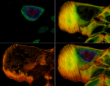
β-tubulin in Tetrahymena (a ciliated protozoan).
-

Partial surface profile of a 1-Euro coin, measured with a Nipkow disk confocal microscope.
-
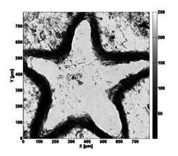
Reflection data for 1-Euro coin.
-
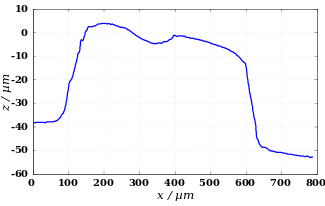
Cross section at y=200 through profile of 1-Euro coin.
-
.tif.png)
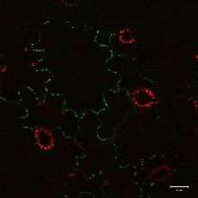
Green signal from anti-tubulin antibody conjugated with Alexa Fluor 488) and nuclei (blue signal from DNA stained with DAPI) in root meristem cells 4-day old Arabidopsis thaliana (Col-0). Scale bar: 5 um.

History
The beginnings: 1940 - 1957
In 1940 Hans Goldmann, ophthalmologist in Bern, Switzerland, developed a slit lamp system to document eye examinations.[14] This system is considered by some later authors as the first confocal optical system.[15][16]
In 1943 Zyun Koana published a confocal system.[17] [15] A figure in this publication clearly shows a confocal transmission beam path. In 1951 Hiroto Naora, a colleague of Koana, described a confocal microscope in the journal Science for spectrophotometry.[18]
The first confocal scanning microscope was built by Marvin Minsky in 1955 and a patent was filed in 1957. The scanning of the illumination point in the focal plane was achieved by moving the stage. No scientific publication was submitted and no images made with it were preserved.[19][20]
The Tandem-Scanning-Microscope
In the 1960s, the Czechoslovak Mojmír Petráň from the Medical Faculty of the Charles University in Plzeň developed the Tandem-Scanning-Microscope, the first commercialized confocal microscope. It was sold by a small company in Czechoslovakia and in the United States by Tracor-Northern (later Noran). It uses a rotating Nipkow disk to generate multiple excitation and emission pinholes.[16][21]
The Czechoslovak patent was filed 1966 by Petráň and Milan Hadravský, a Czechoslovak coworker. A first scientific publication with data and images generated with this microscope was published in the journal Science in 1967. Authors were M. David Egger from Yale University and Petráň.[22] In the footnotes of this paper it is mentioned that Petráň designed the microscope and supervised its construction and that he was partially a „research associate“ at Yale. A second publication from 1968 described theory and technical details of the instrument and had Hadravský and Robert Galambos, the head of the group at Yale, as additional authors.[23] In 1970 the US patent was granted which was filed in 1967.[24]
1969: The first confocal laser scanning microscope
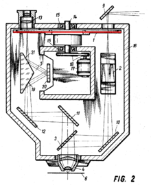
In 1969 and 1971, M. David Egger and Paul Davidovits from Yale University, published two papers describing the first confocal laser scanning microscope.[25][26] It was a point scanner, meaning just one illumination spot was generated. It used epi-Illumination-reflection microscopy for the observation of nerve tissue. A 5 mW Helium-Neon-Laser with 633 nm light was reflected by a semi-transparent mirror towards the objective. The objective was a simple lens with a focal length of 8.5 mm. As opposed to all earlier and most later systems, the sample was scanned by movement of this lens (objective scanning), leading to a movement of the focal point. Reflected light came back to the semitransparent mirror, the transmitted part was focused by another lens on the detection pinhole behind which a photomultiplier tube was placed. The signal was visualized by a CRT of an oscilloscope, the cathode ray was moved simultaneously with the objective. A special device allowed to make Polaroid photos, three of which were shown in the 1971 publication.
The authors speculate about fluorescent dyes for in vivo investigations. They cite Minsky‘s patent, thank Steve Baer, at the time a doctoral student at the Albert Einstein School of Medicine in New York City where he developed a confocal line scanning microscope,[27] for suggesting to use a laser with ‚Minsky‘s microscope‘ and thank Galambos, Hadravsky and Petráň for discussions leading to the development of their microscope. The motivation for their development was that in the Tandem-Scanning-Microscope only a fraction of 10−7 of the illumination light participates in generating the image in the eye piece. Thus, image quality was not sufficient for most biological investigations.[15][28]
1977 – 1985: point scanners with lasers and stage scanning
In 1977 Colin J. R. Sheppard and A. Choudhury, Oxford, UK, published a theoretical analysis of confocal and laser-scanning microscopes.[29] It is probably the first publication using the term "confocal microscope".[15][28]
In 1978, the brothers Christoph Cremer and Thomas Cremer published a design for a confocal laser-scanning-microscope using fluorescent excitation with electronic autofocus. They also suggested a laser point illumination by using a „4π-point-hologramme“.[28][30] This CLSM design combined the laser scanning method with the 3D detection of biological objects labeled with fluorescent markers for the first time.
In 1978 and 1980, the Oxford-group around Colin Sheppard and Tony Wilson described a confocal with epi-laser-illumination, stage scanning and photomultiplier tubes as detectors. The stage could move along the optical axis, allowing optical serial sections.[28]
In 1979 Fred Brakenhoff and coworkers demonstrated that the theoretical advantages of optical sectioning and resolution improvement are indeed achievable in practice. In 1985 this group became the first to publish convincing images taken on a confocal microscope that were able to answer biological questions.[31] Shortly after many more groups started using confocal microscopy to answer scientific questions that until now had remained a mystery due to technological limitations.
In 1983 I. J. Cox und C. Sheppard from Oxford published the first work whereby a confocal microscope was controlled by a computer. The first commercial laser scanning microscope, the stage-scanner SOM-25 was offered by Oxford Optoelectronics (after several take-overs acquired by BioRad) starting in 1982. It was based on the design of the Oxford group.[16][32]
Starting 1985: Laser point scanners with beam scanning
In the mid-1980s, William Bradshaw Amos and John Graham White and colleagues working at the Laboratory of Molecular Biology in Cambridge built the first confocal beam scanning microscope.[33] [34] The stage with the sample was not moving, instead the illumination spot was, allowing faster image acquisition: four images per second with 512 lines each. Hugely magnified intermediate images, due to a 1-2 meter long beam path, allowed the use of a conventional iris diaphragm as a ‘pinhole’, with diameters ~ 1 mm. First micrographs were taken with long-term exposure on film before a digital camera was added. A further improvement allowed zooming into the preparation for the first time. Zeiss, Leitz and Cambridge Instruments had no interest in a commercial production. The Medical Research Council (MRC) finally sponsored development of a prototype. The design was acquired by Bio-Rad, amended with computer control and commercialized as ‘MRC 500’. The successor MRC 600 was later the basis for the development of the first two-photon-fluorescent microscope developed 1990 at Cornell University.[31]
Developments at the University of Stockholm around the same time led to a commercial clsm distributed by the Swedish company Sarastro. The venture was acquired in 1990 by Molecular Dynamics,[35] but the clsm was eventually discontinued. In Germany, Heidelberg Instruments, founded in 1984, developed a clsm which was initially meant for industrial applications, rather than Biology. This instrument was taken over in 1990 by Leica Lasertechnik. Zeiss already had a non-confocal flying-spot laser scanning microscope on the market which was upgraded to a confocal. A report from 1990,[36] mentioning “some” manufacturers of confocals lists: Sarastro, Technical Instrument, Meridian Instruments, Bio-Rad, Leica, Tracor-Northern and Zeiss.[31]
In 1989, Fritz Karl Preikschat, with son Ekhard Preikschat, invented the scanning laser diode microscope for particle-size analysis.[37][38] He and Ekhard Preikschat co-founded Lasentec to commercialize it. In 2001, Lasentec was acquired by Mettler Toledo (NYSE: MTD).[39] About ten thousand systems have been installed globally, mostly in the pharmaceutical industry to provide in-situ control of the crystallization process in large purification systems.
See also
- Two-photon excitation microscopy: Although they use a related technology (both are laser scanning microscopes), multiphoton fluorescence microscopes are not strictly confocal microscopes. The term confocal arises from the presence of a diaphragm in the conjugated focal plane (confocal). This diaphragm is usually absent in multiphoton microscopes.
- Total internal reflection fluorescence microscope (TIRF)
External links
- Virtual CLSM (Java-based)
- animations and explanations on various types of microscopes including fluorescent and confocal microscopes. (Université Paris Sud)
References
- 1 2 Pawley JB (editor) (2006). Handbook of Biological Confocal Microscopy (3rd ed.). Berlin: Springer. ISBN 0-387-25921-X.
- ↑ Filed in 1957 and granted 1961. US 3013467
- ↑ Memoir on Inventing the Confocal Scanning Microscope, Scanning 10 (1988), pp128–138.
- 1 2 Fellers TJ, Davidson MW (2007). "Introduction to Confocal Microscopy". Olympus Fluoview Resource Center. National High Magnetic Field Laboratory. Retrieved 2007-07-25.
- ↑ http://www.patentbuddy.com/Patent/5162941
- ↑ "Data Sheet of NanoFocus µsurf spinning disk confocal white light microscope".
- ↑ "Data Sheet of Sensofar 'PLu neox' Dual technology sensor head combining confocal and Interferometry techniques, as well as Spectroscopic Reflectometry".
- ↑ Vincze L (2005). "Confocal X-ray Fluorescence Imaging and XRF Tomography for Three Dimensional Trace Element Microanalysis". Microscopy and Microanalysis. 11 (Supplement 2). doi:10.1017/S1431927605503167.
- ↑ Patel DV, McGhee CN (2007). "Contemporary in vivo confocal microscopy of the living human cornea using white light and laser scanning techniques: a major review". Clin. Experiment. Ophthalmol. 35 (1): 71–88. doi:10.1111/j.1442-9071.2007.01423.x. PMID 17300580.
- ↑ Hoffman A, Goetz M, Vieth M, Galle PR, Neurath MF, Kiesslich R (2006). "Confocal laser endomicroscopy: technical status and current indications". Endoscopy. 38 (12): 1275–83. doi:10.1055/s-2006-944813. PMID 17163333.
- ↑ Le Person S, Puigalli JR, Baron M, Roques M Near infrared drying of pharmaceutical thin film: experimental analysis of internal mass transport Chemical Engineering and Processing 37 , 257-263 , 1998
- ↑ Hirschfeld, V. ; Hubner, C.G. (2010). "A sensitive and versatile laser scanning confocal optical microscope for single-molecule fluorescence at 77 K". Review of Scientific Instruments 81, (11) 113705-113705-7 http://ieeexplore.ieee.org/xpl/freeabs_all.jsp?arnumber=5640347, doi:10.1063/1.3499260
- ↑ Grazioso, F.; Patton, B. R.; Smith, J.M. (2010). "A high stability beam-scanning confocal optical microscope for low temperature operation". Review of Scientific Instruments 81 (9): 093705-4. http://rsi.aip.org/resource/1/rsinak/v81/i9/p093705_s1. doi:10.1063/1.3484140
- ↑ Hans Goldmann (1939). "Spaltlampenphotographie und –photometrie". Ophthalmologica. 98 (5/6): 257–270. doi:10.1159/000299716. Note: Volume 98 is assigned to the year 1939, however on the first page of the article January 1940 is listed as publication date.
- 1 2 3 4 Colin JR Sheppard (3 November 2009). "Confocal Microscopy. The Development of a Modern Microscopy". Imaging & Microscopy.online
- 1 2 3 Barry R. Masters: Confocal Microscopy And Multiphoton Excitation Microscopy. The Genesis of Live Cell Imaging. SPIE Press, Bellingham, Washington, USA 2006, ISBN 978-0-8194-6118-6, S. 120-121.
- ↑ Zyun Koana (1942). Journal of the Illumination Engineering Institute. 26 (8): 371–385. Missing or empty
|title=(help) The article is available on the website of the journal. The pdf-file labeled „P359 - 402“ is 19020 kilobyte in size and contains also neighboring articles from the same issue. Figure 1b of the article shows the scheme of a confocal transmission beam path. - ↑ Naora, Hiroto (1951). "Microspectrophotometry and cytochemical analysis of nucleic acids.". Science. 114 (2959): 279–280. Bibcode:1951Sci...114..279N. doi:10.1126/science.114.2959.279. PMID 14866220.
- ↑ Marvin Minsky: Microscopy Apparatus. US Patent 3.013.467, filed 7. November 1957, granted 19. December 1961.
- ↑ Marvin Minsky (1988). "Memoir on inventing the confocal scanning microscope". Scanning. 10 (4): 128–138. doi:10.1002/sca.4950100403.
- ↑ Guy Cox: Optical Imaging Techniques in Cell Biology. 1. edition. CRC Press, Taylor & Francis Group, Boca Raton, FL, USA 2006, ISBN 0-8493-3919-7, pages 115-122.
- ↑ Egger MD, Petrăn M (July 1967). "New reflected-light microscope for viewing unstained brain and ganglion cells". Science. 157 (786): 305–7. Bibcode:1967Sci...157..305E. doi:10.1126/science.157.3786.305. PMID 6030094.
- ↑ MOJMÍR PETRÁŇ; MILAN HADRAVSKÝ; M. DAVID EGGER; ROBERT GALAMBOS (1968). "Tandem-Scanning Reflected-Light Microscope". Journal of the Optical Society of America. 58 (5): 661–664. Bibcode:1968JOSA...58..661P. doi:10.1364/JOSA.58.000661.
- ↑ Mojmír Petráň, Milan Hadravský: METHOD AND ARRANGEMENT FOR IMPROVING THE RESOLVING, POWER AND CONTRAST. online at Google Patents, filed 4. November 1967, granted 30. June 1970.
- ↑ Davidovits, P.; Egger, M. D. (1969). "Scanning laser microscope.". Nature. 223 (5208): 831. Bibcode:1969Natur.223..831D. doi:10.1038/223831a0. PMID 5799022.
- ↑ Davidovits, P.; Egger, M. D. (1971). "Scanning laser microscope for biological investigations.". Applied Optics. 10 (7): 1615–1619. Bibcode:1971ApOpt..10.1615D. doi:10.1364/AO.10.001615. PMID 20111173.
- ↑ Barry R. Masters: Confocal Microscopy And Multiphoton Excitation Microscopy. The Genesis of Live Cell Imaging. SPIE Press, Bellingham, Washington, USA 2006, ISBN 978-0-8194-6118-6, pp. 124-125.
- 1 2 3 4 Shinya Inoué (2006). "Chapter 1: Foundations of Confocal Scanned Imaging in Light Microscopy". In James Pawley. Handbook of Biological Confocal Microscopy (3. ed.). Springer Science and Business Media LLC. pp. 1–19. ISBN 978-0-387-25921-5.
- ↑ C.J.R. Sheppard, A. Choudhury: Image Formation in the Scanning Microscope. In: Optica Acta: International Journal of Optics. 24, 1977, S. 1051–1073, doi:10.1080/713819421.
- ↑ C. Cremer, T. Cremer: Considerations on a laser-scanning-microscope with high resolution and depth of field. In: Microscopica acta. Band 81, Nummer 1, September 1978, S. 31–44, ISSN 0044-376X. PMID 713859.
- 1 2 3 Amos, W.B.; White, J.G. (2003). "How the Confocal Laser Scanning Microscope entered Biological Research". Biology of the Cell. 95 (6): 335–342. doi:10.1016/S0248-4900(03)00078-9. PMID 14519550.
- ↑ Cox, I. J.; Sheppard, C. J. (1983). "Scanning optical microscope incorporating a digital framestore and microcomputer.". Applied Optics. 22 (10): 1474. Bibcode:1983ApOpt..22.1474C. doi:10.1364/ao.22.001474. PMID 18195988.
- ↑ White, J. G. (1987). "An evaluation of confocal versus conventional imaging of biological structures by fluorescence light microscopy". The Journal of Cell Biology. 105 (1): 41–48. doi:10.1083/jcb.105.1.41. ISSN 0021-9525. PMC 2114888
 .
. - ↑ Anon (2005). "Dr John White FRS". royalsociety.org. London: Royal Society. Archived from the original on 2015-11-17.
- ↑ Brent Johnson (1 February 1999). "Image Is Everything". The Scientist. online
- ↑ Diana Morgan (23 July 1990). "Confocal Microscopes Widen Cell Biology Career Horizons". The Scientist. online
- ↑ https://www.google.com/patents/US4871251
- ↑ https://www.google.com/patents/US5012118?dq=5,012,118&hl=en&sa=X&ved=0ahUKEwjvw9ry-8bPAhVTz2MKHT7UDEsQ6AEIHjAA
- ↑ http://www.mt.com/us/en/home/products/L1_AutochemProducts/FBRM-PVM-Particle-System-Characterization.html
| Wikimedia Commons has media related to Confocal microscopy. |
| Library resources about Confocal microscopy |
Optical microscopy | ||
|---|---|---|
| Illumination and contrast methods |  | |
| Fluorescence methods | ||
| Sub-diffraction limit techniques | ||