Micrometer
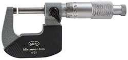
A micrometer (/maɪˈkrɒmᵻtər/ US dict: mī·krŏm′·ĭ·tər), sometimes known as a micrometer screw gauge, is a device incorporating a calibrated screw widely used for precise measurement of components[1] in mechanical engineering and machining as well as most mechanical trades, along with other metrological instruments such as dial, vernier, and digital calipers. Micrometers are usually, but not always, in the form of calipers (opposing ends joined by a frame), which is why micrometer caliper is another common name. The spindle is a very accurately machined screw and the object to be measured is placed between the spindle and the anvil. The spindle is moved by turning the ratchet knob or thimble until the object to be measured is lightly touched by both the spindle and the anvil.
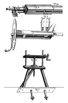
Micrometers are also used in telescopes or microscopes to measure the apparent diameter of celestial bodies or microscopic objects. The micrometer used with a telescope was invented about 1638 by William Gascoigne, an English astronomer.
Colloquially the word micrometer is often shortened to mike or mic (/ˈmaɪk/) (US dict: mīk′).
History of the device and its name
The word micrometer is a neoclassical coinage from Greek micros, meaning "small", and metron, meaning "measure". The Merriam-Webster Collegiate Dictionary[2] says that English got it from French and that its first known appearance in English writing was in 1670. Neither the metre nor the micrometre (μm) nor the micrometer (device) as we know them today existed at that time. However, the people of that time did have much need for, and interest in, the ability to measure small things and small differences. The word was no doubt coined in reference to this endeavor, even if it did not refer specifically to its present-day senses.
The first ever micrometric screw was invented by William Gascoigne in the 17th century, as an enhancement of the vernier; it was used in a telescope to measure angular distances between stars and the relative sizes of celestial objects.
Henry Maudslay built a bench micrometer in the early 19th century that was jocularly nicknamed "the Lord Chancellor" among his staff because it was the final judge on measurement accuracy and precision in the firm's work. In 1844 details of Whitworth's workshop micrometer were published.[3] This was described as having a strong frame of cast iron, the opposite ends of which were two highly finished steel cylinders, which traversed longitudinally by action of screws. The ends of the cylinders where they met was of hemispherical shape. One screw was fitted with a wheel graduated to measure to the ten thousandth of an inch. His object was to furnish ordinary mechanics with an instrument which, while it afforded very accurate indications, was yet not very liable to be deranged by the rough handling of the workshop.
The first documented development of handheld micrometer-screw calipers was by Jean Laurent Palmer of Paris in 1848;[4] the device is therefore often called palmer in French, and tornillo de Palmer ("Palmer screw") in Spanish. (Those languages also use the micrometer cognates: micromètre, micrómetro.) The micrometer caliper was introduced to the mass market in anglophone countries by Brown & Sharpe in 1867,[5] allowing the penetration of the instrument's use into the average machine shop. Brown & Sharpe were inspired by several earlier devices, one of them being Palmer's design. In 1888 Edward W. Morley added to the precision of micrometric measurements and proved their accuracy in a complex series of experiments.
The culture of toolroom accuracy and precision, which started with interchangeability pioneers including Gribeauval, Tousard, North, Hall, Whitney, and Colt, and continued through leaders such as Maudslay, Palmer, Whitworth, Brown, Sharpe, Pratt, Whitney, Leland, and others, grew during the Machine Age to become an important part of combining applied science with technology. Beginning in the early 20th century, one could no longer truly master tool and die making, machine tool building, or engineering without some knowledge of the science of metrology, as well as the sciences of chemistry and physics (for metallurgy, kinematics/dynamics, and quality).
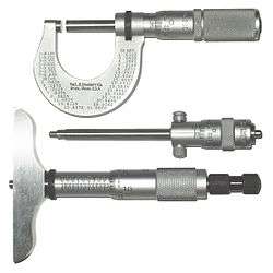
Types
Basic types

Specialized types

Each type of micrometer caliper can be fitted with specialized anvils and spindle tips for particular measuring tasks. For example, the anvil may be shaped in the form of a segment of screw thread, in the form of a v-block, or in the form of a large disc.
- Universal micrometer sets come with interchangeable anvils, such as flat, spherical, spline, disk, blade, point, and knife-edge. The term universal micrometer may also refer to a type of micrometer whose frame has modular components, allowing one micrometer to function as outside mic, depth mic, step mic, etc. (often known by the brand names Mul-T-Anvil and Uni-Mike).
- Blade micrometers have a matching set of narrow tips (blades). They allow, for example, the measuring of a narrow o-ring groove.
- Pitch-diameter micrometers (aka thread mics) have a matching set of thread-shaped tips for measuring the pitch diameter of screw threads.
- Limit mics have two anvils and two spindles, and are used like a snap gauge. The part being checked must pass through the first gap and must stop at the second gap in order to be within specification. The two gaps accurately reflect the top and bottom of the tolerance range.
- Bore micrometer, typically a three-anvil head on a micrometer base used to accurately measure inside diameters.
- Tube micrometers have a cylindrical anvil positioned perpendicularly to a spindle and is used to measure the thickness of tubes.
- Micrometer stops are micrometer heads that are mounted on the table of a manual milling machine, bedways of a lathe, or other machine tool, in place of simple stops. They help the operator to position the table or carriage precisely. Stops can also be used to actuate kickout mechanisms or limit switches to halt an automatic feed system.
- Ball micrometers have ball-shaped (spherical) anvils. They may have one flat and one ball anvil, in which case they are used for measuring tube wall thickness, distance of a hole to an edge, and other distances where one anvil must be placed against a rounded surface. They differ in application from tube micrometers in that they may be used to measure against rounded surfaces which are not tubes, but the ball anvil may also not be able to fit into smaller tubes as easily as a tube micrometer. Ball micrometers with a pair of balls can be used when single-tangential-point contact is desired on both sides. The most common example is in measuring the pitch diameter of screw threads (which is also done with conical anvils or the 3-wire method, the latter of which uses similar geometry as the pair-of-balls approach).
- Bench micrometers are tools for inspection use whose accuracy and precision are around half a micrometre (20 millionths of an inch, "a fifth of a tenth" in machinist jargon) and whose repeatability is around a quarter micrometre ("a tenth of a tenth"). An example is the Pratt & Whitney Supermicrometer brand.
- Digit mics are the type with mechanical digits that roll over.
- Digital mics are the type that uses an encoder to detect the distance and displays the result on a digital screen.
- V mics are outside mics with a small V-block for an anvil. They are useful for measuring the diameter of a circle from three points evenly spaced around it (versus the two points of a standard outside micrometer). An example of when this is necessary is measuring the diameter of 3-flute endmills and twist drills.
Operating principles
Micrometers use the principle of a screw to amplify small distances[6] (that are too small to measure directly) into large rotations of the screw that are big enough to read from a scale. The accuracy of a micrometer derives from the accuracy of the thread-forms that are central to the core of its design. In some cases it is a differential screw. The basic operating principles of a micrometer are as follows:
- The amount of rotation of an accurately made screw can be directly and precisely correlated to a certain amount of axial movement (and vice versa), through the constant known as the screw's lead (/ˈliːd/). A screw's lead is the distance it moves forward axially with one complete turn (360°). (In most threads [that is, in all single-start threads], lead and pitch refer to essentially the same concept.)
- With an appropriate lead and major diameter of the screw, a given amount of axial movement will be amplified in the resulting circumferential movement.
For example, if the lead of a screw is 1 mm, but the major diameter (here, outer diameter) is 10 mm, then the circumference of the screw is 10π, or about 31.4 mm. Therefore, an axial movement of 1 mm is amplified (magnified) to a circumferential movement of 31.4 mm. This amplification allows a small difference in the sizes of two similar measured objects to correlate to a larger difference in the position of a micrometer's thimble. In some micrometers, even greater accuracy is obtained by using a differential screw adjuster to move the thimble in much smaller increments than a single thread would allow.[7][8][9]
In classic-style analog micrometers, the position of the thimble is read directly from scale markings on the thimble and sleeve (for names of parts see next section). A vernier scale is often included, which allows the position to be read to a fraction of the smallest scale mark. In digital micrometers, an electronic readout displays the length digitally on an LCD on the instrument. There also exist mechanical-digit versions, like the style of car odometers where the numbers "roll over".
Parts
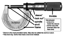
A micrometer is composed of:
- Frame
- The C-shaped body that holds the anvil and barrel in constant relation to each other. It is thick because it needs to minimize flexion, expansion, and contraction, which would distort the measurement.
The frame is heavy and consequently has a high thermal mass, to prevent substantial heating up by the holding hand/fingers. It is often covered by insulating plastic plates which further reduce heat transference.
Explanation: if one holds the frame long enough so that it heats up by 10 °C, then the increase in length of any 10 cm linear piece of steel is of magnitude 1/100 mm. For micrometers this is their typical accuracy range.
Micrometers typically have a specified temperature at which the measurement is correct (often 20 °C [68 °F], which is generally considered "room temperature" in a room with HVAC). Toolrooms are generally kept at 20 °C [68 °F]. - Anvil
- The shiny part that the spindle moves toward, and that the sample rests against.
- Sleeve / barrel / stock
- The stationary round component with the linear scale on it, sometimes with vernier markings. In some instruments the scale is marked on a tight-fitting but movable cylindrical sleeve fitting over the internal fixed barrel. This allows zeroing to be done by slightly altering the position of the sleeve.[10][11]
- Lock nut / lock-ring / thimble lock
- The knurled component (or lever) that one can tighten to hold the spindle stationary, such as when momentarily holding a measurement.
- Screw
- (not seen) The heart of the micrometer, as explained under "Operating principles". It is inside the barrel. This references the fact that the usual name for the device in German is Messschraube, literally "measuring screw".
- Spindle
- The shiny cylindrical component that the thimble causes to move toward the anvil.
- Thimble
- The component that one's thumb turns. Graduated markings.
- Ratchet stop
- (not shown in illustration) Device on end of handle that limits applied pressure by slipping at a calibrated torque.
Reading
Customary/Imperial system
The spindle of a micrometer graduated for the Imperial and US customary measurement systems has 40 threads per inch, so that one turn moves the spindle axially 0.025 inch (1 ÷ 40 = 0.025), equal to the distance between adjacent graduations on the sleeve. The 25 graduations on the thimble allow the 0.025 inch to be further divided, so that turning the thimble through one division moves the spindle axially 0.001 inch (0.025 ÷ 25 = 0.001). Thus, the reading is given by the number of whole divisions that are visible on the scale of the sleeve, multiplied by 25 (the number of thousandths of an inch that each division represents), plus the number of that division on the thimble which coincides with the axial zero line on the sleeve. The result will be the diameter expressed in thousandths of an inch. As the numbers 1, 2, 3, etc., appear below every fourth sub-division on the sleeve, indicating hundreds of thousandths, the reading can easily be taken.
Suppose the thimble were screwed out so that graduation 2, and three additional sub-divisions, were visible on the sleeve (as shown in the image), and that graduation 1 on the thimble coincided with the axial line on the sleeve. The reading would then be 0.2000 + 0.075 + 0.001, or .276 inch.
Metric system
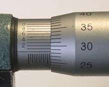
The spindle of an ordinary metric micrometer has 2 threads per millimetre, and thus one complete revolution moves the spindle through a distance of 0.5 millimeter. The longitudinal line on the sleeve is graduated with 1 millimetre divisions and 0.5 millimetre subdivisions. The thimble has 50 graduations, each being 0.01 millimetre (one-hundredth of a millimetre). Thus, the reading is given by the number of millimetre divisions visible on the scale of the sleeve plus the particular division on the thimble which coincides with the axial line on the sleeve.
Suppose that the thimble were screwed out so that graduation 5, and one additional 0.5 subdivision were visible on the sleeve (as shown in the image), and that graduation 28 on the thimble coincided with the axial line on the sleeve. The reading then would be 5.00 + 0.5 + 0.28 = 5.78 mm.
Vernier
Some micrometers are provided with a vernier scale on the sleeve in addition to the regular graduations. These permit measurements within 0.001 millimetre to be made on metric micrometers, or 0.0001 inches on inch-system micrometers.
The additional digit of these micrometers is obtained by finding the line on the sleeve vernier scale which exactly coincides with one on the thimble. The number of this coinciding vernier line represents the additional digit.
Thus, the reading for metric micrometers of this type is the number of whole millimetres (if any) and the number of hundredths of a millimetre, as with an ordinary micrometer, and the number of thousandths of a millimetre given by the coinciding vernier line on the sleeve vernier scale.
For example, a measurement of 5.783 millimetres would be obtained by reading 5.5 millimetres on the sleeve, and then adding 0.28 millimetre as determined by the thimble. The vernier would then be used to read the 0.003 (as shown in the image).
Inch micrometers are read in a similar fashion.
Note: 0.01 millimetre = 0.000393 inch, and 0.002 millimetre = 0.000078 inch (78 millionths) or alternatively, 0.0001 inch = 0.00254 millimetres. Therefore, metric micrometers provide smaller measuring increments than comparable inch unit micrometers—the smallest graduation of an ordinary inch reading micrometer is 0.001 inch; the vernier type has graduations down to 0.0001 inch (0.00254 mm). When using either a metric or inch micrometer, without a vernier, smaller readings than those graduated may of course be obtained by visual interpolation between graduations.
Torque repeatability via torque-limiting ratchets or sleeves
A micrometer reading is not accurate if the thimble is over- or under-torqued. A useful feature of many micrometers is the inclusion of a torque-limiting device on the thimble—either a spring-loaded ratchet or a friction sleeve. Without this device, workers may overtighten the micrometer on the work, causing the mechanical advantage of the screw to tighten the screw threads or squeeze the material, giving an inaccurate measurement. However, with a thimble that will ratchet or friction slip at a certain torque, the micrometer will not continue to advance once sufficient resistance is encountered. This results in greater accuracy and repeatability of measurements—most especially for low-skilled or semi-skilled workers, who may not have developed the light, consistent touch of a skilled user.
It might seem that there would be no such thing as too little torque on the thimble, because if zero tightening of the threads is the goal, then the less torque, the better. However, there is a practical limit on this ideal. Some tiny amount of torque, although very slight, is involved in the normal hand movements of well-practiced micrometer use. It is light but not truly zero, because zero is impractical for a skillful feel of how the contact is being made. And the calibration reflects this amount, as tiny as it is. If one then changes to an "afraid to even touch it" sort of gingerliness, one is being inconsistent with the norm that the calibration reflects, resulting in a reading that is 1 to 3 tenths too big (on a typical metal part).
Related to this torque topic is interuser variation in what is normal. It is important to try not to have an idiosyncratic touch, because although it works perfectly well for intrauser consistency, it interferes with interuser consistency. Some people use a rather heavy touch as a matter of habit, and this is fine in that they can get highly accurate readings as long as they calibrate their micrometer accordingly. The problem arises when they use someone else's micrometer, or when someone uses theirs. The heavy-touch user gets false-small readings, and the normal-touch user gets false-big readings. This may not arise in one-person shops, but teams of workers sharing company-owned instruments must be capable of interpersonal consistency to do close-tolerance work successfully. There is a good and easy way to synchronize on this topic: it is simply to get used to the "feel" of how much torque it takes to slip the typical friction sleeve or click the typical ratchet thimble—and then incorporate that same feel into every use of a micrometer, even those that have no sleeve or ratchet. This is proper training for the machining trade, although it is not uncommon to encounter coworkers who were not well trained on this point. In many cases it seems that in drilling the "don't overtorque" idea into trainees' heads, an opposite extreme is mistakenly taught, where the user thinks the goal is to compete with everyone else on who can generate the lightest touch. Individuals naturally differ in their touch, so such a competition is not as effective at generating interuser consistency as is "imagining that every thimble has a sleeve to slip."
Bench micrometers of the "super-mic" class entirely obviate this interuser variation by having the user dial the handwheel until a needle reads zero on a gauge, producing the same pressure on every reading.
Calibration: testing and adjusting
Zeroing
On most micrometers, a small pin spanner is used to turn the sleeve relative to the barrel, so that its zero line is repositioned relative to the markings on the thimble. There is usually a small hole in the sleeve to accept the spanner's pin. This calibration procedure will cancel a zero error: the problem that the micrometer reads nonzero when its jaws are closed.
Testing
A standard one-inch micrometer has readout divisions of .001 inch and a rated accuracy of +/- .0001 inch[12] ("one tenth", in machinist parlance). Both the measuring instrument and the object being measured should be at room temperature for an accurate measurement; dirt, abuse, and low operator skill are the main sources of error.[13]
The accuracy of micrometers is checked by using them to measure gauge blocks,[14] rods, or similar standards whose lengths are precisely and accurately known. If the gauge block is known to be 0.7500" ± .00005" ("seven-fifty plus or minus fifty millionths", that is, "seven hundred fifty thou plus or minus half a tenth"), then the micrometer should measure it as 0.7500". If the micrometer measures 0.7503", then it is out of calibration. Cleanliness and low (but consistent) torque are especially important when calibrating—each tenth (that is, ten-thousandth of an inch), or hundredth of a millimeter, "counts"; each is important. A mere spec of dirt, or a mere bit too much squeeze, obscure the truth of whether the instrument is able to read correctly. The solution is simply conscientiousness—cleaning, patience, due care and attention, and repeated measurements (good repeatability assures the calibrator that his/her technique is working correctly).
Calibration typically checks the error at 3 to 5 points along the range. Only one can be adjusted to zero. If the micrometer is in good condition, then they are all so near to zero that the instrument seems to read essentially "-on" all along its range; no noticeable error is seen at any locale. In contrast, on a worn-out micrometer (or one that was poorly made to begin with), one can "chase the error up and down the range", that is, move it up or down to any of various locales along the range, by adjusting the sleeve, but one cannot eliminate it from all locales at once.
Calibration can also include the condition of the tips (flat and parallel), any ratchet, and linearity of the scale.[15] Flatness and parallelism are typically measured with a gauge called an optical flat, a disc of glass or plastic ground with extreme accuracy to have flat, parallel faces, which allows light bands to be counted when the micrometer's anvil and spindle are against it, revealing their amount of geometric inaccuracy.
Commercial machine shops, especially those that do certain categories of work (military or commercial aerospace, nuclear power industry, and others), are required by various standards organizations (such as ISO, ANSI, ASME,[16] ASTM, SAE, AIA, the U.S. military, and others) to calibrate micrometers and other gauges on a schedule (often annually), to affix a label to each gauge that gives it an ID number and a calibration expiration date, to keep a record of all the gauges by ID number, and to specify in inspection reports which gauge was used for a particular measurement.
Not all calibration is an affair for metrology labs. A micrometer can be calibrated on-site anytime, at least in the most basic and important way (if not comprehensively), by measuring a high-grade gauge block and adjusting to match. Even gauges that are calibrated annually and within their expiration timeframe should be checked this way every month or two, if they are used daily. They usually will check out OK as needing no adjustment.
The accuracy of the gauge blocks themselves is traceable through a chain of comparisons back to a master standard such as the international prototype meter. This bar of metal, like the international prototype kilogram, is maintained under controlled conditions at the International Bureau of Weights and Measures headquarters in France, which is one of the principal measurement standards laboratories of the world. These master standards have extreme-accuracy regional copies (kept in the national laboratories of various countries, such as NIST), and metrological equipment makes the chain of comparisons. Because the definition of the meter is now based on a light wavelength, the international prototype meter is not quite as indispensable as it once was. But such master gauges are still important for calibrating and certifying metrological equipment. Equipment described as "NIST traceable" means that its comparison against master gauges, and their comparison against others, can be traced back through a chain of documentation to equipment in the NIST labs. Maintaining this degree of traceability requires some expense, which is why NIST-traceable equipment is more expensive than non-NIST-traceable. But applications needing the highest degree of quality control mandate the cost.
Adjustment
A micrometer that has been zeroed and tested and found to be off might be restored to accuracy by further adjustment. If the error originates from the parts of the micrometer being worn out of shape and size, then restoration of accuracy by this means is not possible; rather, repair (grinding, lapping, or replacing of parts) is required. For standard kinds of instruments, in practice it is easier and faster, and often no more expensive, to buy a new one rather than pursue refurbishment
See also
References
- ↑ Encyclopedia Americana (1988) "Micrometer" Encyclopedia Americana 19: 500 ISBN 0-7172-0119-8 (set)
- ↑ "micrometer". Merriam-Webster Dictionary.
- ↑ "Whitworth's workshop micrometer", The Practical Mechanic and Engineer's magazine, Nov 1844, pp43-44
- ↑ Roe 1916:212.
- ↑ Roe 1916:210-213, 215.
- ↑
- Loo Kang, Wee; Hwee Tiang, Ning (2014), "Vernier caliper and micrometer computer models using Easy Java Simulation and its pedagogical design feature-ideas to augment learning with real instruments", Physics Education, 49 (5), arXiv:1408.3803
 , doi:10.1088/0031-9120/49/5/493
- Loo Kang, Wee; Hwee Tiang, Ning (2014), "Vernier caliper and micrometer computer models using Easy Java Simulation and its pedagogical design feature-ideas to augment learning with real instruments", Physics Education, 49 (5), arXiv:1408.3803
- ↑ US patent 343478, McArthur, Duncan, "Micrometer Calipers", issued 1880-02-08
- ↑ M.M. Lanz & Betancourt, translated from the original French (1817). Analytical essay on the construction of machines. London: R. Ackermann. pp. 14–15, 181 Plate 1 fig D3.
- ↑ "Micrometer Heads Series 110-Differential Screw Translator(extra-Fine Feeding) Type". Product Catalog. Mitutoyo, U.S.A. Retrieved December 11, 2012.
- ↑ Waitelet, Ermand L. (1964). "Micrometer with adjustable barrel sleeve. US 3131482 A". Google patents. Retrieved 26 August 2016.
- ↑ "Precision Measuring and Gaging". www.waybuilder.net. Archived from the original on 26 August 2016.
- ↑ http://www.starrett.com/download/222_p1_5.pdf GENERAL MICROMETER INFORMATION
- ↑ http://www.mahr.de/index.php?NodeID=13120 MICROMETER ACCURACY: Drunken Threads and Slip-sticks
- ↑ BS EN ISO 3650: "Geometrical product specifications (GPS). Length standards. Gauge blocks" (1999)
- ↑ http://ittc.sname.org/2006_recomm_proc/7.6-02-04.res.pdf ITTC – Recommended Procedures : Sample Work Instructions Calibration of Micrometers.
- ↑ ASME B89.1.13 - 2013 Micrometers.
Bibliography
- Roe, Joseph Wickham (1916), English and American Tool Builders, New Haven, Connecticut: Yale University Press, LCCN 16011753. Reprinted by McGraw-Hill, New York and London, 1926 (LCCN 27-24075); and by Lindsay Publications, Inc., Bradley, Illinois, (ISBN 978-0-917914-73-7).
- ISO 3611: "Geometrical product specifications (GPS). Dimensional measuring equipment. Micrometers for external measurements. Design and metrological characteristics" (2010)
- BS 870: "Specification for external micrometers" (2008)
- BS 959: "Specification for internal micrometers (including stick micrometers)" (2008)
- BS 6468: "Specification for depth micrometers" (2008)
External links
| Wikimedia Commons has media related to Micrometer. |
- Print files including lessons and quizzes for teachers and students of the subject matter.
- Simulator to practice reading and interpreting one-thousandth of a millimeter outside micrometer
- How to read a micrometer screw gauge