Tesla coil
 | |
| Uses | Application in educational demonstrations, novelty lighting, music |
|---|---|
| Inventor | Nikola Tesla |
| Related items | Transformer, electromagnetic field, resonance |
The Tesla coil is an electrical resonant transformer circuit designed by inventor Nikola Tesla around 1891 [1] as a power supply for his "System of Electric Lighting".[2] It is used to produce high-voltage, low-current, high frequency alternating-current electricity.[3][4][5][6][7][8][9] Tesla experimented with a number of different configurations consisting of two, or sometimes three, coupled resonant electric circuits.
Tesla used these transformers to conduct innovative experiments in electrical lighting, phosphorescence, X-ray generation, high frequency alternating current phenomena, electrotherapy, and the transmission of electrical energy without wires. Tesla coil circuits were used commercially in sparkgap radio transmitters for wireless telegraphy until the 1920s,[1][10][11][12][13][14] and in medical equipment such as electrotherapy and violet ray devices. Today their main use is for entertainment and educational displays, although small coils are still used today as leak detectors for high vacuum systems.[9]
Operation

A Tesla coil is a radio frequency oscillator that drives an air-core double-tuned resonant transformer to produce high voltages at low currents.[10][15][16][17][18][19] Tesla's original circuits as well as most modern coils use a simple spark gap to excite oscillations in the tuned transformer. More sophisticated designs use transistor or thyristor[15] switches or vacuum tube electronic oscillators to drive the resonant transformer. These are described in later sections.
Tesla coils can produce output voltages from 50 kilovolts to several million volts for large coils.[15][17][19] The alternating current output is in the low radio frequency range, usually between 50 kHz and 1 MHz.[17][19] Although some oscillator-driven coils generate a continuous alternating current, most Tesla coils have a pulsed output;[15] the high voltage consists of a rapid string of pulses of radio frequency alternating current.
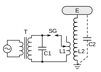
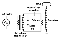
The common spark-excited Tesla coil circuit, shown below, consists of these components:[16][20]
- A high voltage supply transformer (T), to step the AC mains voltage up to a high enough voltage to jump the spark gap. Typical voltages are between 5 and 30 kilovolts (kV).[20]
- A capacitor (C1) that forms a tuned circuit with the primary winding L1 of the Tesla transformer
- A spark gap (SG) that acts as a switch in the primary circuit
- The Tesla coil (L1, L2), an air-core double-tuned resonant transformer, which generates the high output voltage.
- Optionally, a capacitive electrode (top load) (E) in the form of a smooth metal sphere or torus attached to the secondary terminal of the coil. Its large surface area suppresses premature corona discharge and streamer arcs, increasing the Q factor and output voltage.
Resonant transformer

The specialized transformer used in the Tesla coil, also called the resonance transformer, oscillation transformer or radio-frequency (RF) transformer, functions differently from an ordinary transformer used in AC power circuits.[21][22][23] While an ordinary transformer is designed to transfer energy efficiently from primary to secondary winding, the resonant transformer is also designed to temporarily store electrical energy. Each winding has a capacitance across it and functions as an LC circuit (resonant circuit, tuned circuit), storing oscillating electrical energy, analogously to a tuning fork. The primary winding (L1) consisting of a relatively few turns of heavy copper wire or tubing, is connected to a capacitor (C1) through the spark gap (SG).[15][16] The secondary winding (L2) consists of many turns (hundreds to thousands) of fine wire on a hollow cylindrical form inside the primary. The secondary is not connected to an actual capacitor, but it also functions as an LC circuit, the inductance (L2) resonates with (C2), the sum of the stray parasitic capacitance between the windings of the coil, and the capacitance of the toroidal metal electrode attached to the high voltage terminal. The primary and secondary circuits are tuned so they resonate at the same frequency, they have the same resonant frequency. This allows them to exchange energy, so the oscillating current alternates back and forth between the primary and secondary coils.
The peculiar design of the coil is dictated by the need to achieve low resistive energy losses (high Q factor) at high frequencies,[17] which results in the largest secondary voltages:
- Ordinary power transformers have an iron core to increase the magnetic coupling between the coils. However at high frequencies an iron core causes energy losses due to eddy currents and hysteresis, so it is not used in the Tesla coil.[23]
- Ordinary transformers are designed to be "tightly coupled". Due to the iron core and close proximity of the windings, they have a high mutual inductance (M), the coupling coefficient is close to unity 0.95 - 1.0, which means almost all the magnetic field of the primary winding passes through the secondary.[21][23] The Tesla transformer in contrast is "loosely coupled",[15][23] the primary winding is larger in diameter and spaced apart from the secondary,[16] so the mutual inductance is lower and the coupling coefficient is only 0.05 to 0.2; meaning only 5% to 20% of the magnetic field of each coil passes through the other.[15][20] This slows the exchange of energy between the primary and secondary coils, which allows the oscillating energy to stay in the secondary circuit longer before it returns to the primary and begins dissipating in the spark.
- Each winding is also limited to a single layer of wire, which reduces proximity effect losses. The primary carries very high currents. Since high frequency current mostly flows on the surface of conductors due to skin effect, it is often made of copper tubing or strip with a large surface area to reduce resistance, and its turns are spaced apart, which reduces proximity effect losses.[24][25]
The output circuit can have two forms:
- Unipolar - One end of the secondary winding is connected to a single high voltage terminal, the other end is grounded. This type is used in modern coils designed for entertainment. The primary winding is located near the bottom, low potential end of the secondary, to minimize arcs between the windings. Since the ground (Earth) serves as the return path for the high voltage, streamer arcs from the terminal tend to jump to any nearby grounded object.
- Bipolar - Neither end of the secondary winding is grounded, and both are brought out to high voltage terminals. The primary winding is located at the center of the secondary coil, equidistant between the two high potential terminals, to discourage arcing.
Operation cycle
The circuit operates in a rapid repeating cycle in which the supply transformer (T) charges the primary capacitor (C1) up, which then discharges in a spark through the spark gap, creating a brief pulse of oscillating current in the primary circuit which excites a high oscillating voltage across the secondary:[18][20][23][26]
- Current from the supply transformer (T) charges the capacitor (C1) to a high voltage.
- When the voltage across the capacitor reaches the breakdown voltage of the spark gap (SG) a spark starts, reducing the spark gap resistance to a very low value. This completes the primary circuit and current from the capacitor flows through the primary coil (L1). The current flows rapidly back and forth between the plates of the capacitor through the coil, generating radio frequency oscillating current in the primary circuit at the circuit's resonant frequency.
- The oscillating magnetic field of the primary winding induces an oscillating current in the secondary winding (L2), by Faraday's law of induction. Over a number of cycles, the energy in the primary circuit is transferred to the secondary. The total energy in the tuned circuits is limited to the energy originally stored in the capacitor C1, so as the oscillating voltage in the secondary increases in amplitude ("ring up") the oscillations in the primary decrease to zero ("ring down"). Although the ends of the secondary coil are open, it also acts as a tuned circuit due to the capacitance (C2), the sum of the parasitic capacitance between the turns of the coil plus the capacitance of the toroid electrode E. Current flows rapidly back and forth through the secondary coil between its ends. Because of the small capacitance, the oscillating voltage across the secondary coil which appears on the output terminal is much larger than the primary voltage.
- The secondary current creates a magnetic field that induces voltage back in the primary coil, and over a number of additional cycles the energy is transferred back to the primary. This process repeats, the energy shifting rapidly back and forth between the primary and secondary tuned circuits. The oscillating currents in the primary and secondary gradually die out ("ring down") due to energy dissipated as heat in the spark gap and resistance of the coil.
- When the current through the spark gap is no longer sufficient to keep the air in the gap ionized, the spark stops ("quenches"), terminating the current in the primary circuit. The oscillating current in the secondary may continue for some time.
- The current from the supply transformer begins charging the capacitor C1 again and the cycle repeats.
This entire cycle takes place very rapidly, the oscillations dying out in a time of the order of a millisecond. Each spark across the spark gap produces a pulse of damped sinusoidal high voltage at the output terminal of the coil. Each pulse dies out before the next spark occurs, so the coil generates a string of damped waves, not a continuous sinusoidal voltage.[18] The high voltage from the supply transformer that charges the capacitor is a 50 or 60 Hz sine wave. Depending on how the spark gap is set, usually one or two sparks occur at the peak of each half-cycle of the mains current, so there are more than a hundred sparks per second. Thus the spark at the spark gap appears continuous, as do the high voltage streamers from the top of the coil.
The supply transformer (T) secondary winding is connected across the primary tuned circuit. It might seem that the transformer would be a leakage path for the RF current, damping the oscillations. However its large inductance gives it a very high impedance at the resonant frequency, so it acts as an open circuit to the oscillating current. If the supply transformer has inadequate leakage inductance, radio frequency chokes are placed in its secondary leads to block the RF current.
Oscillation frequency
To produce the largest output voltage, the primary and secondary tuned circuits are adjusted to resonance with each other. The resonant frequencies of the primary and secondary circuits, and , are determined by the inductance and capacitance in each circuit[17][18][21]


Generally the secondary is not adjustable, so the primary circuit is tuned, usually by a moveable tap on the primary coil L1, until it resonates at the same frequency as the secondary

Thus the condition for resonance between primary and secondary is

The resonant frequency of Tesla coils is in the low radio frequency (RF) range, usually between 50 kHz and 1 MHz. However, because of the impulsive nature of the spark they produce broadband radio noise, and without shielding can be a significant source of RFI, interfering with nearby radio and television reception.
Output voltage
In a resonant transformer the high voltage is produced by resonance; the output voltage is not proportional to the turns ratio, as in an ordinary transformer.[23][27] It can be calculated approximately from conservation of energy. At the beginning of the cycle, when the spark starts, all of the energy in the primary circuit is stored in the primary capacitor . If is the voltage at which the spark gap breaks down, which is usually close to the peak output voltage of the supply transformer T, this energy is


During the "ring up" this energy is transferred to the secondary circuit. Although some is lost as heat in the spark and other resistances, in modern coils, over 85% of the energy ends up in the secondary.[18] At the peak () of the secondary sinusoidal voltage waveform, all the energy in the secondary is stored in the capacitance between the ends of the secondary coil


Assuming no energy losses, . Substituting into this equation and simplifying, the peak secondary voltage is[17][18][23]


The second formula above is derived from the first using .[23] Since the capacitance of the secondary coil is very small compared to the primary capacitor, the primary voltage is stepped up to a high value.[18]

It might seem that the output voltage could be increased indefinitely by reducing and . However, as the output voltage increases, it reaches the point where the air next to the high voltage terminal ionizes and corona discharges, brush discharges and streamer arcs break out from the secondary coil. This happens when the electric field strength exceeds the dielectric strength of the air, about 30 kV per centimeter, and occurs first at sharp points and edges on the high voltage terminal. The resulting energy loss damps the oscillation, so the above lossless model is no longer accurate, and the voltage does not reach the theoretical maximum above.[18][23][24]

The top load or "toroid" electrode
Most unipolar Tesla coil designs have a spherical or toroidal shaped metal electrode on the high voltage terminal. Although the "toroid" increases the secondary capacitance, which tends to reduce the peak voltage, its main effect is that its large diameter curved surface reduces the potential gradient (electric field) at the high voltage terminal, increasing the voltage threshold at which corona and streamer arcs form. Suppressing premature air breakdown and energy loss allows the voltage to build to higher values on the peaks of the waveform, creating longer, more spectacular streamers.[23]
If the top electrode is large and smooth enough, the electric field at its surface may never get high enough even at the peak voltage to cause air breakdown, and air discharges will not occur. Some entertainment coils have a sharp "spark point" projecting from the torus to start discharges.
Types
The term "Tesla coil" is applied to a number of high voltage resonant transformer circuits.
Tesla coil circuits can be classified by the type of "excitation" they use, what type of circuit is used to apply current to the primary winding of the resonant transformer:[28][29]
- Spark-excited or Spark Gap Tesla Coil (SGTC) - This type uses a spark gap to switch pulses of current through the primary, exciting oscillation in the transformer. This pulsed (disruptive) drive creates a pulsed high voltage output. Spark gaps have disadvantages due to the high primary currents they must handle. They produce a very loud noise while operating, noxious ozone gas, and high temperatures which often require a cooling system. The energy dissipated in the spark also reduces the Q factor and the output voltage.
- Static spark gap - This is the most common type, which was described in detail in the previous section. It is used in most entertainment coils. An AC voltage from a high voltage supply transformer charges a capacitor, which discharges through the spark gap. The spark rate is not adjustable but is determined by the line frequency. Multiple sparks may occur on each half-cycle, so the pulses of output voltage may not be equally-spaced.
- Static triggered spark gap - Commercial and industrial circuits often apply a DC voltage from a power supply to charge the capacitor, and use high voltage pulses generated by an oscillator applied to a triggering electrode to trigger the spark.[15] This allows control of the spark rate and exciting voltage. Commercial spark gaps are often enclosed in an insulating gas atmosphere such as sulfur hexafluoride, reducing the length and thus the energy loss in the spark.
- Rotary spark gap - These use a spark gap consisting of electrodes around the periphery of a wheel rotated by a motor, which create sparks when they pass by a stationary electrode. Tesla used this type on his big coils, and they are used today on large entertainment coils. The rapid separation speed of the electrodes quenches the spark quickly, allowing "first notch" quenching, making possible higher voltages. The wheel is usually driven by a synchronous motor, so the sparks are synchronized with the AC line frequency, the spark occurring at the same point on the AC waveform on each cycle, so the primary pulses are repeatable.
- Switched or Solid State Tesla Coil (SSTC) - These use power semiconductor devices, usually thyristors or transistors such as MOSFETs or IGBTs,[15] to switch pulses of current from a DC power supply through the primary winding. They provide pulsed (disruptive) excitation without the disadvantages of a spark gap: the loud noise and high temperatures. They allow fine control of the voltage, pulse rate and exciting waveform. This type is used in most commercial, industrial, and research applications[15] as well as higher quality entertainment coils.
- Single resonant solid state Tesla coil (SRSSTC) - In this circuit the primary does not have a capacitor and so is not a tuned circuit; only the secondary is. The pulses of current to the primary from the switching transistors excite resonance in the secondary tuned circuit. Single tuned SSTCs are simpler, but don't have as high a Q and cannot produce as high voltage from a given input power as the DRSSTC.
- Dual Resonant Solid State Tesla Coil (DRSSTC) - A double tuned Tesla transformer driven by solid state switching supply. This functions similarly to the double tuned spark excited circuits.
- Singing Tesla coil or musical Tesla coil - This is a Tesla coil which can be played like a musical instrument, with its high voltage discharges reproducing simple musical tones. The drive current pulses applied to the primary are modulated at an audio rate by a solid state "interrupter" circuit, causing the arc discharge from the high voltage terminal to emit sounds. Only tones and simple chords have been produced so far; the coil cannot function as a loudspeaker, reproducing complex music or voice sounds. The sound output is controlled by a keyboard or MIDI file applied to the circuit through a MIDI interface. Two modulation techniques have been used: AM (amplitude modulation of the exciting voltage) and PFM (pulse-frequency modulation). These are mainly built as novelties for entertainment.
- Continuous wave - In these the transformer is driven by a feedback oscillator, which applies a sinusoidal current to the transformer. The primary tuned circuit serves as the tank circuit of the oscillator, and the circuit resembles a radio transmitter. Unlike the previous circuits which generate a pulsed output, they generate a continuous sine wave output. Power vacuum tubes are often used as active devices instead of transistors because they are more robust and tolerant of overloads. In general, continuous excitation produces lower output voltages from a given input power than pulsed excitation.
Tesla circuits can also be classified by how many coils (inductors) they contain:[30][31]
- Two coil or double-resonant circuits - Virtually all present Tesla coils use the two coil resonant transformer, consisting of a primary winding to which current pulses are applied, and a secondary winding that produces the high voltage, invented by Tesla in 1891. The term "Tesla coil" normally refers to these circuits.
- Three coil, triple-resonant, or magnifier circuits - These are circuits with three coils, based on Tesla's "magnifying transmitter" circuit which he began experimenting with sometime before 1898 and installed in his Colorado Springs lab 1899-1900, and patented in 1902.[32][33][34] They consist of a two coil air-core step-up transformer similar to the Tesla transformer, with the secondary connected to a third coil not magnetically coupled to the others, called the "extra" or "resonator" coil, which is series-fed and resonates with its own capacitance. The presence of three energy-storing tank circuits gives this circuit more complicated resonant behavior. It is the subject of research, but has been used in few practical applications.
History
Tesla invented his "Tesla Coil" around 1891 while he was repeating and then expanding on Heinrich Hertz' experiments that had discovered electromagnetic radiation three years earlier.[35] Tesla decided to power his setup with the high speed alternator he had been developing as part of an improved arc lighting system but found that the high frequency current overheated the iron core and melted the insulation between the primary and secondary windings in the Ruhmkorff coil originally used in Hertz setup. To fix this problem Tesla changed the design so that there was an air gap instead of insulating material between the primary and secondary windings and made it so that the iron core could be moved to different positions in or out of the coil.[36] Tesla also found he needed to put the capacitor normally used in such setups between his alternator and the coil's primary winding to avoid burning out the coil. By adjusting the coil and the capacitor Tesla found he could take advantage of the resonance set up between the two to achieve even higher frequencies.[37]
In Tesla's coil transformer the capacitor, upon break-down of a short spark gap, became connected to a coil of a few turns (the primary winding set), forming a resonant circuit with the frequency of oscillation, usually 20–100 kHz, determined by the capacitance of the capacitor and the inductance of the coil. The capacitor was charged to the voltage necessary to rupture the air of the gap during the input line cycle, about 10 kV by a line-powered transformer connected across the gap. The line transformer was designed to have higher than normal leakage inductance to tolerate the short circuit occurring while the gap remained ionized, or for the few milliseconds until the high frequency current had died away.
The spark gap is set up so that its breakdown occurs at a voltage somewhat less than the peak output voltage of the transformer in order to maximize the voltage across the capacitor. The sudden current through the spark gap causes the primary resonant circuit to ring at its resonant frequency. The ringing primary winding magnetically couples energy into the secondary over several RF cycles, until all of the energy that was originally in the primary has been transferred to the secondary. Ideally, the gap would then stop conducting (quench), trapping all of the energy into the oscillating secondary circuit. Usually the gap reignites, and energy in the secondary transfers back to the primary circuit over several more RF cycles. Cycling of energy may repeat for several times until the spark gap finally quenches. Once the gap stops conducting, the transformer begins recharging the capacitor. Depending on the breakdown voltage of the spark gap, it may fire many times during a mains AC cycle.
A more prominent secondary winding, with vastly more turns of thinner wire than the primary, was positioned to intercept some of the magnetic field of the primary. The secondary was designed to have the same frequency of resonance as the primary using only the stray capacitance of the winding itself to ground and that of any "top hat" terminal placed at the top of the secondary. The lower end of the long secondary coil must be grounded to the surroundings.
The later and higher-power coil design has a single-layer primary and secondary. These Tesla coils are often used by hobbyists and at venues such as science museums to produce long sparks. The American Electrician[38] gives a description of an early Tesla coil wherein a glass battery jar, 15 × 20 cm (6 × 8 in) is wound with 60 to 80 turns of AWG No. 18 B & S magnet wire (0.823 mm²). Into this is slipped a primary consisting of eight to ten turns of AWG No. 6 B & S wire (13.3 mm2) and the whole combination is immersed in a vessel containing linseed or mineral oil.[39]
Magnifying transmitter
Tesla built a laboratory in Colorado Springs and between 1899-1900 performed experiments on wireless power transmission there. The Colorado Springs laboratory possessed one of the largest Tesla coils ever built, which Tesla called a "magnifying transmitter" as it was intended to transmit power to a distant receiver. With an input power of 300 kilowatts it could produce potentials in the 12 to 20 megavolt range at a frequency of 150 kHz, creating huge 140 foot "lightning" bolts. The magnifying transmitter design is somewhat different from the classic two-coil Tesla coil circuit. In addition to the primary and secondary coils it had a third "resonator" coil, not magnetically coupled to the others, attached to the top terminal of the secondary. When driven by the secondary it produced additional high voltage by resonance, being adjusted to resonate with its own parasitic capacitance at the frequency of the other coils.
The Colorado Springs apparatus consisted of a 53-foot diameter Tesla coil around the periphery of the lab, with a single-turn primary buried in the ground and a secondary of 50 turns of heavy wire on a 9 foot high circular "fence". The primary was connected to a bank of oil capacitors to make a tuned circuit, excited by a rotary spark gap at 20 - 40 kilovolts from a powerful utility transformer. The top of the secondary was connected to a 20 ft diameter "resonator" coil in the center of the room, attached to a telescoping 143 foot "antenna" with a 30-inch metal ball on top which could project through the roof of the lab.
Wardenclyffe coil
Tesla's 1902 design for his advanced magnifying transmitter used a top terminal consisting of a metal frame in the shape of a toroid, covered with hemispherical plates (constituting a very large conducting surface). The top terminal has relatively small capacitance, charged to as high a voltage as practicable.[40] The outer surface of the elevated conductor is where the electrical voltage chiefly occurs. It had a large radius of curvature, or was composed of separate elements which, irrespective of their own radii of curvature, were arranged close to each other so that the outside ideal surface enveloping them has a large radius.[41] This design allowed the terminal to support very high voltages without generating corona or sparks. Tesla, during his patent application process, described a variety of resonator terminals at the top of this later coil.[42]


1. Circuit of basic Tesla magnifying transmitter from his February 19, 1900 patent.[43] The generator symbol at bottom represents any source of RF current; in Tesla's coils this was a resonant circuit composed of the primary excited by a spark gap
2. Circuit of bipolar magnifying transmitter design Tesla used in his Wardenclyffe tower plant.
3. Colorado Springs coil in operation at 12 million volts. The 20 ft diameter 30 ft. high "resonator" coil is shown. The streamer discharge is 65 feet across.
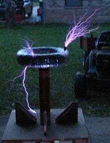
Modern-day Tesla coils

..JPG)
.JPG)
Modern high-voltage enthusiasts usually build Tesla coils similar to some of Tesla's "later" 2-coil air-core designs. These typically consist of a primary tank circuit, a series LC (inductance-capacitance) circuit composed of a high-voltage capacitor, spark gap and primary coil, and the secondary LC circuit, a series-resonant circuit consisting of the secondary coil plus a terminal capacitance or "top load". In Tesla's more advanced (magnifier) design, a third coil is added. The secondary LC circuit is composed of a tightly coupled air-core transformer secondary coil driving the bottom of a separate third coil helical resonator. Modern 2-coil systems use a single secondary coil. The top of the secondary is then connected to a topload terminal, which forms one 'plate' of a capacitor, the other 'plate' being the earth (or "ground"). The primary LC circuit is tuned so that it resonates at the same frequency as the secondary LC circuit. The primary and secondary coils are magnetically coupled, creating a dual-tuned resonant air-core transformer. Earlier oil-insulated Tesla coils needed large and long insulators at their high-voltage terminals to prevent discharge in air. Later Tesla coils spread their electric fields over larger distances to prevent high electrical stresses in the first place, thereby allowing operation in free air. Most modern Tesla coils also use toroid-shaped output terminals. These are often fabricated from spun metal or flexible aluminum ducting. The toroidal shape helps to control the high electrical field near the top of the secondary by directing sparks outward and away from the primary and secondary windings.
A more complex version of a Tesla coil, termed a "magnifier" by Tesla, uses a more tightly coupled air-core resonance "driver" transformer (or "master oscillator") and a smaller, remotely located output coil (called the "extra coil" or simply the resonator) that has a large number of turns on a relatively small coil form. The bottom of the driver's secondary winding is connected to ground. The opposite end is connected to the bottom of the extra coil through an insulated conductor that is sometimes called the transmission line. Since the transmission line operates at relatively high RF voltages, it is typically made of 1" diameter metal tubing to reduce corona losses. Since the third coil is located some distance away from the driver, it is not magnetically coupled to it. RF energy is instead directly coupled from the output of the driver into the bottom of the third coil, causing it to "ring up" to very high voltages. The combination of the two-coil driver and third coil resonator adds another degree of freedom to the system, making tuning considerably more complex than that of a 2-coil system. The transient response for multiple resonance networks (of which the Tesla magnifier is a sub-set) has only recently been solved.[44] It is now known that a variety of useful tuning "modes" are available, and in most operating modes the extra coil will ring at a different frequency than the master oscillator.[45]
Primary switching
Modern transistor or vacuum tube Tesla coils do not use a primary spark gap. Instead, the transistor(s) or vacuum tube(s) provide the switching or amplifying function necessary to generate RF power for the primary circuit. Solid-state Tesla coils use the lowest primary operating voltage, typically between 155 and 800 volts, and drive the primary winding using either a single, half-bridge, or full-bridge arrangement of bipolar transistors, MOSFETs or IGBTs to switch the primary current. Vacuum tube coils typically operate with plate voltages between 1500 and 6000 volts, while most spark gap coils operate with primary voltages of 6,000 to 25,000 volts. The primary winding of a traditional transistor Tesla coil is wound around only the bottom portion of the secondary coil. This configuration illustrates operation of the secondary as a pumped resonator. The primary 'induces' alternating voltage into the bottom-most portion of the secondary, providing regular 'pushes' (similar to providing properly timed pushes to a playground swing). Additional energy is transferred from the primary to the secondary inductance and top-load capacitance during each "push", and secondary output voltage builds (called 'ring-up'). An electronic feedback circuit is usually used to adaptively synchronize the primary oscillator to the growing resonance in the secondary, and this is the only tuning consideration beyond the initial choice of a reasonable top-load.

In a dual resonant solid-state Tesla coil (DRSSTC), the electronic switching of the solid-state Tesla coil is combined with the resonant primary circuit of a spark-gap Tesla coil. The resonant primary circuit is formed by connecting a capacitor in series with the primary winding of the coil, so that the combination forms a series tank circuit with a resonant frequency near that of the secondary circuit. Because of the additional resonant circuit, one manual and one adaptive tuning adjustment are necessary. Also, an interrupter is usually used to reduce the duty cycle of the switching bridge, to improve peak power capabilities; similarly, IGBTs are more popular in this application than bipolar transistors or MOSFETs, due to their superior power handling characteristics. A current-limiting circuit is usually used to limit maximum primary tank current (which must be switched by the IGBT's) to a safe level. Performance of a DRSSTC can be comparable to a medium-power spark-gap Tesla coil, and efficiency (as measured by spark length versus input power) can be significantly greater than a spark-gap Tesla coil operating at the same input power.
Practical aspects of design
High voltage production
A large Tesla coil of more modern design often operates at very high peak power levels, up to many megawatts (millions of watts[46]). It is therefore adjusted and operated carefully, not only for efficiency and economy, but also for safety. If, due to improper tuning, the maximum voltage point occurs below the terminal, along the secondary coil, a discharge (spark) may break out and damage or destroy the coil wire, supports, or nearby objects.
Here, the spark gap shorts the high frequency across the first transformer that is supplied by alternating current. An inductance, not shown, protects the transformer. This design is favoured when a relatively fragile neon sign transformer is used.

With the capacitor in parallel to the first transformer and the spark gap in series to the Tesla-coil primary, the AC supply transformer must be capable of withstanding high voltages at high frequencies.
Tesla experimented with these, and many other, circuit configurations (see right). The Tesla coil primary winding, spark gap and tank capacitor are connected in series. In each circuit, the AC supply transformer charges the tank capacitor until its voltage is sufficient to break down the spark gap. The gap suddenly fires, allowing the charged tank capacitor to discharge into the primary winding. Once the gap fires, the electrical behavior of either circuit is identical. Experiments have shown that neither circuit offers any marked performance advantage over the other.
However, in the typical circuit, the spark gap's short circuiting action prevents high-frequency oscillations from 'backing up' into the supply transformer. In the alternate circuit, high amplitude high frequency oscillations that appear across the capacitor also are applied to the supply transformer's winding. This can induce corona discharges between turns that weaken and eventually destroy the transformer's insulation. Experienced Tesla coil builders almost exclusively use the top circuit, often augmenting it with low pass filters (resistor and capacitor (RC) networks) between the supply transformer and spark gap to help protect the supply transformer. This is especially important when using transformers with fragile high-voltage windings, such as neon sign transformers (NSTs). Regardless of which configuration is used, the HV transformer must be of a type that self-limits its secondary current by means of internal leakage inductance. A normal (low leakage inductance) high-voltage transformer must use an external limiter (sometimes called a ballast) to limit current. NSTs are designed to have high leakage inductance to limit their short circuit current to a safe level.
Tuning precautions
The primary coil's resonant frequency is tuned to that of the secondary, by using low-power oscillations, then increasing the power (and retuning if necessary) until the system operates properly at maximum power. While tuning, a small projection (called a "breakout bump") is often added to the top terminal in order to stimulate corona and spark discharges (sometimes called streamers) into the surrounding air. Tuning can then be adjusted so as to achieve the longest streamers at a given power level, corresponding to a frequency match between the primary and secondary coil. Capacitive 'loading' by the streamers tends to lower the resonant frequency of a Tesla coil operating under full power. A toroidal topload is often preferred to other shapes, such as a sphere. A toroid with a major diameter that is much larger than the secondary diameter provides improved shaping of the electrical field at the topload. This provides better protection of the secondary winding (from damaging streamer strikes) than a sphere of similar diameter. And, a toroid permits fairly independent control of topload capacitance versus spark breakout voltage. A toroid's capacitance is mainly a function of its major diameter, while the spark breakout voltage is mainly a function of its minor diameter.
Air discharges
While generating discharges, electrical energy from the secondary and toroid is transferred to the surrounding air as electrical charge, heat, light, and sound. The process is similar to charging or discharging a capacitor, except that a Tesla coil uses AC instead of DC. The current that arises from shifting charges within a capacitor is called a displacement current. Tesla coil discharges are formed as a result of displacement currents as pulses of electrical charge are rapidly transferred between the high-voltage toroid and nearby regions within the air (called space charge regions). Although the space charge regions around the toroid are invisible, they play a profound role in the appearance and location of Tesla coil discharges.
When the spark gap fires, the charged capacitor discharges into the primary winding, causing the primary circuit to oscillate. The oscillating primary current creates an oscillating magnetic field that couples to the secondary winding, transferring energy into the secondary side of the transformer and causing it to oscillate with the toroid capacitance to ground. Energy transfer occurs over a number of cycles, until most of the energy that was originally in the primary side is transferred to the secondary side. The greater the magnetic coupling between windings, the shorter the time required to complete the energy transfer. As energy builds within the oscillating secondary circuit, the amplitude of the toroid's RF voltage rapidly increases, and the air surrounding the toroid begins to undergo dielectric breakdown, forming a corona discharge.
As the secondary coil's energy (and output voltage) continue to increase, larger pulses of displacement current further ionize and heat the air at the point of initial breakdown. This forms a very electrically conductive "root" of hotter plasma, called a leader, that projects outward from the toroid. The plasma within the leader is considerably hotter than a corona discharge, and is considerably more conductive. In fact, its properties are similar to an electric arc. The leader tapers and branches into thousands of thinner, cooler, hair-like discharges (called streamers). The streamers look like a bluish 'haze' at the ends of the more luminous leaders. The streamers transfer charge between the leaders and toroid to nearby space charge regions. The displacement currents from countless streamers all feed into the leader, helping to keep it hot and electrically conductive.
The primary break rate of sparking Tesla coils is slow compared to the resonant frequency of the resonator-topload assembly. When the switch closes, energy is transferred from the primary LC circuit to the resonator where the voltage rings up over a short period of time up culminating in the electrical discharge. In a spark gap Tesla coil, the primary-to-secondary energy transfer process happens repetitively at typical pulsing rates of 50–500 times per second, depending on the frequency of the input line voltage. At these rates, previously-formed leader channels do not get a chance to fully cool down between pulses. So, on successive pulses, newer discharges can build upon the hot pathways left by their predecessors. This causes incremental growth of the leader from one pulse to the next, lengthening the entire discharge on each successive pulse. Repetitive pulsing causes the discharges to grow until the average energy available from the Tesla coil during each pulse balances the average energy being lost in the discharges (mostly as heat). At this point, dynamic equilibrium is reached, and the discharges have reached their maximum length for the Tesla coil's output power level. The unique combination of a rising high-voltage radio frequency envelope and repetitive pulsing seem to be ideally suited to creating long, branching discharges that are considerably longer than would be otherwise expected by output voltage considerations alone. High-voltage, low-energy discharges create filamentary multibranched discharges which are purplish-blue in colour. High-voltage, high-energy discharges create thicker discharges with fewer branches, are pale and luminous, almost white, and are much longer than low-energy discharges, because of increased ionisation. A strong smell of ozone and nitrogen oxides will occur in the area. The important factors for maximum discharge length appear to be voltage, energy, and still air of low to moderate humidity. There are comparatively few scientific studies about the initiation and growth of pulsed lower-frequency RF discharges, so some aspects of Tesla coil air discharges are not as well understood when compared to DC, power-frequency AC, HV impulse, and lightning discharges.
Applications
Tesla coil circuits were used commercially in sparkgap radio transmitters for wireless telegraphy until the 1920s,[1][10][11] and in electrotherapy and pseudomedical devices such as violet ray. Today, although small Tesla coils are used as leak detectors in scientific high vacuum systems[9] and igniters in arc welders,[47] their main use is entertainment and educational displays, Tesla coils are built by many high-voltage enthusiasts, research institutions, science museums, and independent experimenters. Although electronic circuit controllers have been developed, Tesla's original spark gap design is less expensive and has proven extremely reliable.
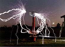
Entertainment
Tesla coils are very popular devices among certain electrical engineers and electronics enthusiasts. Builders of Tesla coils as a hobby are called "coilers". A very large Tesla coil, designed and built by Syd Klinge, is shown every year at the Coachella Valley Music and Arts Festival, in Coachella, Indio, California, USA. People attend "coiling" conventions where they display their home-made Tesla coils and other electrical devices of interest. Austin Richards, a physicist in California, created a metal Faraday Suit in 1997 that protects him from Tesla Coil discharges. In 1998, he named the character in the suit Doctor MegaVolt and has performed all over the world and at Burning Man 9 different years.
Low-power Tesla coils are also sometimes used as a high-voltage source for Kirlian photography.[48]
Tesla coils can also be used to generate sounds, including music, by modulating the system's effective "break rate" (i.e., the rate and duration of high power RF bursts) via MIDI data and a control unit. The actual MIDI data is interpreted by a microcontroller which converts the MIDI data into a PWM output which can be sent to the Tesla coil via a fiber optic interface.[49][50] The YouTube video Super Mario Brothers theme in stereo and harmony on two coils shows a performance on matching solid state coils operating at 41 kHz. The coils were built and operated by designer hobbyists Jeff Larson and Steve Ward. The device has been named the Zeusaphone, after Zeus, Greek god of lightning, and as a play on words referencing the Sousaphone. The idea of playing music on the singing Tesla coils flies around the world and a few followers[51] continue the work of initiators. An extensive outdoor musical concert has demonstrated using Tesla coils during the Engineering Open House (EOH) at the University of Illinois at Urbana-Champaign. The Icelandic artist Björk used a Tesla coil in her song "Thunderbolt" as the main instrument in the song. The musical group ArcAttack uses modulated Tesla coils and a man in a chain-link suit to play music.
The world's largest currently existing two-coil Tesla coil is a 130,000-watt unit, part of a 38-foot-tall (12 m) sculpture titled Electrum owned by Alan Gibbs and currently resides in a private sculpture park at Kakanui Point near Auckland, New Zealand.[52] The most powerful conical Tesla coil (1.5 million volts) was installed in 2002 at the Mid-America Science Museum in Hot Springs, Arkansas.[53] This is a replica of the Griffith Observatory conical coil installed in 1936.
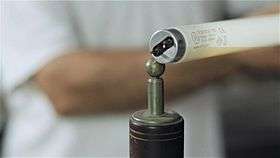
Vacuum system leak detectors
Scientists working with high vacuum systems test for the presence of tiny pin holes in the apparatus (especially a newly blown piece of glassware) using high-voltage discharges produced by a small handheld Tesla coil. When the system is evacuated the high voltage electrode of the coil is played over the outside of the apparatus. The discharge travels through any pin hole immediately below it, producing a corona discharge inside the evacuated space which illuminates the hole, indicating points that need to be annealed or reblown before they can be used in an experiment.
Wireless power


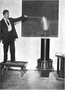
In the period from 1891 to 1904 Tesla used his resonant transformer circuit to perform experiments in wireless power transfer.[56][57][58] With this basic resonance transformer design concept he was able to transmit electrical energy over short distances without interconnecting wires by resonant magneto-inductive coupling.[57][58][59][60][61] The transformer's primary LC circuit acted as a transmitter. The transformer's secondary LC circuit was tuned to the primary LC circuit's resonant frequency and acted as a receiver. He found the Tesla coil transformer itself could be configured as a wireless transmitter and used to transfer energy by resonant electro-inductive coupling. While demonstrating this technology during lectures before the American Institute of Electrical Engineers in 1891, the Institution of Electrical Engineers in 1892, and at the 1893 Columbian Exposition in Chicago he was able to wirelessly power lamps from across the stage and out into the room.[62][63][64] At his Colorado Springs laboratory (1899-1900), he assembled an improved version of his resonance transformer called a Tesla coil magnifying transmitter, capable of producing voltages on the order of 10 megavolts. In one demonstration, using just the oscillator's primary LC circuit energized to only one-twentieth of the oscillator's full capacity, he was able to light three incandescent lamps by resonant magneto-inductive coupling at a distance of about one hundred feet.[65][66] The resonant inductive coupling technique pioneered by Tesla has recently become a central concept in modern wireless power development and is being widely used in short- and mid-range wireless transmission systems[58] like cellphone charging pads. The resonant magnetic induction and resonant capacitive induction coupling techniques make use of "near-field" effects,[58] meaning the energy transferred decreases with the sixth power of the distance between transmitter and receiver,[58][67][68][69] so they are not suitable for the long range transmission of electrical energy.
Tesla's top priority at Colorado Springs was the development of a wireless system that could transmit electrical energy over great distances, as proposed in his 1900 Century magazine article.[70][71][72][73] He claimed that it is possible to transmit energy on a worldwide scale, applying a method that involves electrical conduction through the earth and the periodic alteration of Earth's electrostatic charge.[74][75][76] In 1900 he received the patents SYSTEM OF TRANSMISSION OF ELECTRICAL ENERGY and APPARATUS FOR TRANSMISSION OF ELECTRICAL ENERGY.[77][78] They describe two hypothetical wireless stations, one consisting of a large Tesla coil magnifying transmitter and the other a similar Tesla coil receiver, each with an elevated air terminal electrode suspended by balloon at an altitude of 30,000 feet (9,100 m), where the atmospheric pressure is lower. Tesla believed atmospheric ionization would allow energy to be transmitted at high voltages (millions of volts) over long distances by electrical conduction. Another claim was that such a high elevation of the air terminal electrodes is not absolutely necessary.[79] By 1901 Tesla had come to believe the entire planet could be made to act as a giant electrical resonator and that by driving sufficiently powerful current pulses into Earth at a harmonic of its fundamental resonant frequency using a grounded Tesla coil transmitter working against a relatively short elevated capacitive air terminal electrode, its natural electrostatic potential could be made to oscillate, and this alternating current could be received at any location with a Tesla coil receiver and similar capacitive air terminal electrode arrangement tuned to resonance with the transmitter.[80][81] Tesla demonstrated the coupling of a Tesla coil transmitter and a Tesla coil receiver in an experiment at his Experimental Station in Colorado Springs, transmitting enough electrical energy to power a 10-watt incandescent lamp at a distance of 1,938 feet (591 m) from the station's magnifying transmitter.[54][55]
Tesla claimed his ideas were proven but there is little direct corroboration that he ever transferred power beyond the above-mentioned demonstrations.[57][82][83][84][85][86][87][88][89] His belief that long range wireless energy transmission is possible by means of the magnifying transmitter was based upon empirical scientific evidence gathered at Colorado Springs.[54][55][90] While he claimed to have created terrestrial stationary waves, he was never able to demonstrate a fully developed prototype World Wireless system based upon the earth resonance principle.[91] The only known report of the long range transmission and reception of electrical energy by Tesla himself is a statement made to attorney Drury W. Cooper that in 1899 he collected quantitative transmission-reception data at a distance of about 10 miles (16 km).[92] There are four other reports of Tesla having achieved long range wireless power transfer. The first is the wireless operation of lamps and electric motors at a distance of 15 miles (24 km).[93] The second is the wireless transfer of "power enough to light a lamp at 30 km" (19 miles).[94] The third is the wireless transfer of sufficient power to light an incandescent lamp of approximately 10 W at a distance of 1,938 feet (591 m) from the magnifying transmitter's ground plate to the point of reception.[54][55] The fourth is a statement that was made by Tesla biographer John J. O'Neill, based upon "fragmentary material published in a number of publications," that Tesla lit 200 incandescent lamps at a distance of 26 miles (42 km).[85][88][95][96] Tesla does not mention this demonstration in his writings; it does not appear in his Colorado laboratory notes,[54][55] There is no independent confirmation of it having taken place[85][97] but recent mathematical analysis suggest it could have been possible using the 1899 Colorado Springs magnifying transmitter.[98]
Hazards
The 'skin effect'
The dangers of contact with high-frequency electric current are sometimes perceived as being less than at lower frequencies, because the subject usually does not feel pain or a 'shock'. This is often erroneously attributed to skin effect, a phenomenon that tends to inhibit alternating current from flowing inside conducting media. It was thought that in the body, Tesla currents travelled close to the skin surface, making them safer than lower-frequency electric currents.
Although skin effect limits Tesla currents to the outer fraction of an inch in metal conductors, the 'skin depth' of human flesh is deeper than that of a metallic conductor due to higher resistivity and lower permittivity. Calculations of skin depth of body tissues at the frequency of Tesla coils show that it can be greater than the thickness of the body.[99][100][101] Thus there seems to be nothing to prevent high-frequency Tesla currents from passing through deeper portions of a subject's body, such as vital organs and blood vessels, which may be better conducting. The reason for the lack of pain is that a human being's nervous system does not sense the flow of potentially dangerous electric currents above 15–20 kHz; essentially, for nerves to be activated, a significant number of ions must cross their membranes before the current (and hence voltage) reverses. Since the body no longer provides a warning 'shock', novices may touch the output streamers of small Tesla coils without feeling painful shocks. However, anecdotal evidence among Tesla coil experimenters indicates temporary tissue damage may still occur and be observed as muscle pain, joint pain, or tingling for hours or even days afterwards. This is believed to be caused by the damaging effects of internal current flow, and is especially common with continuous wave, solid state or vacuum tube Tesla coils operating at relatively low frequencies (tens to hundreds of kHz). It is possible to generate very high frequency currents (tens to hundreds of MHz) that do have a smaller penetration depth in flesh. These are often used for medical and therapeutic purposes such as electrocauterization and diathermy. The designs of early diathermy machines were based on Tesla coils or Oudin coils.
Large Tesla coils and magnifiers can deliver dangerous levels of high-frequency current, and they can also develop significantly higher voltages (often 250,000–500,000 volts, or more). Because of the higher voltages, large systems can deliver higher energy, potentially lethal, repetitive high-voltage capacitor discharges from their top terminals. Doubling the output voltage quadruples the electrostatic energy stored in a given top terminal capacitance. Professionals usually use other means of protection such as a Faraday cage or a metallic mail suit to prevent dangerous currents from entering their bodies.
The most serious dangers associated with Tesla coil operation are associated with the primary circuit. It is capable of delivering a sufficient current at a significant voltage to stop the heart of a careless experimenter. Because these components are not the source of the trademark visual or auditory coil effects, they may easily be overlooked as the chief source of hazard. Should a high-frequency arc strike the exposed primary coil while, at the same time, another arc has also been allowed to strike to a person, the ionized gas of the two arcs forms a circuit that may conduct lethal, low-frequency current from the primary into the person.
Further, great care must be taken when working on the primary section of a coil even when it has been disconnected from its power source for some time. The tank capacitors can remain charged for days with enough energy to deliver a fatal shock. Proper designs always include 'bleeder resistors' to bleed off stored charge from the capacitors. In addition, a safety shorting operation is performed on each capacitor before any internal work is performed.[102]
Related patents
- Tesla's patents
- See also: List of Tesla patents
- "Electrical Transformer Or Induction Device". U.S. Patent No. 433,702, August 5, 1890[103]
- "Means for Generating Electric Currents", U.S. Patent No. 514,168, February 6, 1894
- "Electrical Transformer", Patent No. 593,138, November 2, 1897
- "Method Of Utilizing Radiant Energy", Patent No. 685,958 November 5, 1901
- "Method of Signaling", U.S. Patent No. 723,188, March 17, 1903
- "System of Signaling", U.S. Patent No. 725,605, April 14, 1903
- "Apparatus for Transmitting Electrical Energy", January 18, 1902, U.S. Patent 1,119,732, December 1, 1914 (available at U.S. Patent 1,119,732
- Others' patents
- J. S. Stone, U.S. Patent 714,832, "Apparatus for amplifying electromagnetic signal-waves". (Filed January 23, 1901; Issued December 2, 1902)
- A. Nickle, U.S. Patent 2,125,804, "Antenna". (Filed May 25, 1934; Issued August 2, 1938)
- William W. Brown, U.S. Patent 2,059,186, "Antenna structure". (Filed May 25, 1934; Issued October 27, 1936).
- Robert B. Dome, U.S. Patent 2,101,674, "Antenna". (Filed May 25, 1934; Issued December 7, 1937)
- Armstrong, E. H., U.S. Patent 1,113,149, "Wireless receiving system". 1914.
- Armstrong, E. H., U.S. Patent 1,342,885, "Method of receiving high frequency oscillation". 1922.
- Armstrong, E. H., U.S. Patent 1,424,065, "Signalling system". 1922.
- Gerhard Freiherr Du Prel, U.S. Patent 1,675,882, "High frequency circuit". (Filed August 11, 1925; Issued July 3, 1928)
- Leydorf, G. F., U.S. Patent 3,278,937, "Antenna near field coupling system". 1966.
- Van Voorhies, U.S. Patent 6,218,998, "Toroidal helical antenna"
- Gene Koonce, U.S. Patent 6,933,819, "Multifrequency electro-magnetic field generator". (Filed October 29, 2004; Issued August 23, 2005)[104]
See also
- Bifilar coil
- Henry Leroy Transtrom, an inventor and showman who worked with high voltage electricity.
- List of Tesla patents
- Oudin coil, invented in 1893 by Paul Marie Oudin
- Wireless energy transfer
References
- 1 2 3 Uth, Robert (December 12, 2000). "Tesla coil". Tesla: Master of Lightning. PBS.org. Retrieved 2008-05-20.
- ↑ U.S. Patent No. 454,622, Nikola Tesla, SYSTEM OF ELECTRIC LIGHTING, filed 23 June 1891; granted 25 April 1891
- ↑ Dommermuth-Costa, Carol (1994). Nikola Tesla: A Spark of Genius. Twenty-First Century Books. p. 75. ISBN 0-8225-4920-4.
- ↑ "Tesla coil". Museum of Electricity and Magnetism, Center for Learning. National High Magnetic Field Laboratory website, Florida State Univ. 2011. Retrieved September 12, 2013.
- ↑ "Instruction and Application Manual" (PDF). Model 10-206 Tesla Coil. Science First, Serrata, Pty. educational equipment website. 2006. p. 2. Retrieved September 12, 2013.
- ↑ Cheney, Margaret (2011). Tesla: Man Out of Time. Simon and Schuster. p. 87. ISBN 1-4516-7486-4.
- ↑ Constable, George; Bob Somerville (2003). A Century of Innovation: Twenty Engineering Achievements that Transformed Our Lives. Joseph Henry Press. p. 70. ISBN 0-309-08908-5.
- ↑ Smith, Craig B. (2008). Lightning: Fire from the Sky. Dockside Consultants Inc. ISBN 0-615-24869-1.
- 1 2 3 Plesch, P. H. (2005). High Vacuum Techniques for Chemical Syntheses and Measurements. Cambridge University Press. p. 21. ISBN 0-521-67547-2.
- 1 2 3 Tilbury, Mitch (2007). The Ultimate Tesla Coil Design and Construction Guide. New York: McGraw-Hill Professional. p. 1. ISBN 0-07-149737-4.
- 1 2 Ramsey, Rolla (1937). Experimental Radio (4th ed.). New York: Ramsey Publishing. p. 175.
- ↑ Mazzotto, Domenico (1906). Wireless telegraphy and telephony. Whittaker and Co. p. 146.
- ↑ Sarkar, T. K.; Mailloux, Robert; Oliner, Arthur A.; et al. (2006). History of Wireless. John Wiley & Sons. pp. 286, 84. ISBN 0-471-78301-3., archive
- ↑ "Unfortunately, the common misunderstanding by most people today is that the Tesla coil is merely a device that produces a spectacular exhibit of sparks which tittilates audiences. Nevertheless, its circuitry is fundamental to all radio transmission" Belohlavek, Peter; Wagner, John W (2008). Innovation: The Lessons of Nikola Tesla. Blue Eagle Group. p. 110. ISBN 9876510096.
- 1 2 3 4 5 6 7 8 9 10 Haddad, A.; Warne, D.F. (2004). Advances in High Voltage Engineering. IET. p. 605. ISBN 0852961588.
- 1 2 3 4 Naidu, M. S.; Kamaraju, V. (2013). High Voltage Engineering. Tata McGraw-Hill Education. p. 167. ISBN 1259062899.
- 1 2 3 4 5 6 Sprott, Julien C. (2006). Physics Demonstrations: A Sourcebook for Teachers of Physics. Univ. of Wisconsin Press. pp. 192–195. ISBN 0299215806.
- 1 2 3 4 5 6 7 8 Anderson, Barton B. (November 24, 2000). "The Classic Tesla Coil: A dual-tuned resonant transformer" (PDF). Tesla Coils. Terry Blake, 3rd webpage. Retrieved July 26, 2015.
- 1 2 3 Denicolai, Marco (May 30, 2001). "Tesla Transformer for Experimentation and Research" (PDF). Thesis for Licentiate Degree. Electrical and Communications Engineering Dept., Helsinki Univ. of Technology, Helsinki, Finland: 2–6. Retrieved July 26, 2015.
- 1 2 3 4 Denicolai, 2001, Tesla Transformer for Experimentation and Research, Ch.2, p. 8-10
- 1 2 3 Gerekos, Christopher (2012). "The Tesla Coil" (PDF). Thesis. Physics Dept., Université Libre de Bruxelles, Brussels, Belgium: 20–22. Archived from the original (PDF) on October 1, 2015. Retrieved July 27, 2015., reprinted on The Zeus Tesla Coil, HazardousPhysics.com
- ↑ Gottlieb, Irving (1998). Practical Transformer Handbook: for Electronics, Radio and Communications Engineers. Newnes. pp. 103–114. ISBN 0080514561.
- 1 2 3 4 5 6 7 8 9 10 Burnett, Richie (2008). "Operation of the Tesla Coil". Richie's Tesla Coil Web Page. Richard Burnett private website. Retrieved July 24, 2015.
- 1 2 Burnett, Richie (2008). "Tesla Coil Components, P. 2". Richie's Tesla Coil Web Page. Richard Burnett private website. Retrieved July 24, 2015.
- ↑ Gerekos, 2012, The Tesla Coil, p. 38-42 Archived June 23, 2007, at the Wayback Machine.
- ↑ Gerekos, 2012, The Tesla Coil, p. 15-18 Archived June 23, 2007, at the Wayback Machine.
- ↑ Gerekos, 2012, The Tesla Coil, p. 19-20 Archived June 23, 2007, at the Wayback Machine.
- ↑ "Tesla Coils - Frequently Asked Questions". oneTesla website. oneTesla Co., Cambridge, MA. 2012. Retrieved August 2, 2015.
- ↑ Denicolai, 2001, Tesla Transformer for Experimentation and Research, Ch.2, p. 11-17
- ↑ Gerekos, 2012, The Tesla Coil, p. 1, 23 Archived June 23, 2007, at the Wayback Machine.
- ↑ Denicolai, 2001, Tesla Transformer for Experimentation and Research, Ch.2, p. 10
- ↑ US Patent No. 1119732, Nikola Tesla Apparatus for transmitting electrical energy, filed January 18, 1902; granted December 1, 1914
- ↑ Sarkar et al. (2006) History of Wireless, p. 279-280, archive
- ↑ Reed, John Randolph (2000). "Designing high-gain triple resonant Tesla transformers" (PDF). Dept. of Engineering and Computer Science, Univ. of Central Florida. Retrieved August 2, 2015.
- ↑ W. Bernard Carlson, Tesla: Inventor of the Electrical Age, Princeton University Press - 2013, page 120
- ↑ W. Bernard Carlson, Tesla: Inventor of the Electrical Age, Princeton University Press - 2013, page 122
- ↑ W. Bernard Carlson, Tesla: Inventor of the Electrical Age, Princeton University Press - 2013, page 124
- ↑ This is an early electronics magazine.
- ↑ (Norrie, pg. 34–35)
- ↑ N. Tesla, US patent No. 1, 119, 732. "I employ a terminal of relatively small capacity, which I charge to as high a pressure as practicable." (emphasis added) Tesla's lightning rod, U.S. Patent 1,266,175, goes more into this subject. The reader is also referred to the U.S. Patent 645,576, U.S. Patent 649,621, U.S. Patent 787,412, and U.S. Patent 1,119,732.
- ↑ Patent 1119732, lines 53 to 69; In order to develop the greatest energy in the circuit without flashover to the coil, Tesla elevated the conductor with a large radius of curvature or was composed of separate elements which in conglomeration had a large radius.
- ↑ In Selected Patent Wrappers from the National Archives, by John Ratzlaff (1981; ISBN 0-9603536-2-3), a variety of terminals was described by Tesla. Besides the torus-shaped terminal, he applied for hemispherical and oblate terminals. A total of five different terminals were applied for, but four were rejected.
- ↑ US Patent No. 649621, Nikola Tesla, Apparatus for transmission of electrical energy, filed February 19, 1900, granted May 15, 1900
- ↑ de Queiroz, Antonio Carlos M. "Generalized Multiple LC Resonance Networks". International Symposium on Circuits and Systems. IEEE. 3: 519–522.
- ↑ de Queiroz, Antonio Carlos M. "Designing a Tesla Magnifier". Retrieved April 12, 2015.
- ↑ This is equivalent to hundreds of thousands of horsepower
- ↑ Gottlieb, Irving (1998). Practical Transformer Handbook. Newnes. p. 551. ISBN 0080514561.
- ↑ "Corona Discharge Electrographic Imaging Technology" Kirlianlab.com.
- ↑ Interview with ArcAttack on Odd Instruments
- ↑ Duckon 2007-Steve Ward's Singing Tesla Coil video Archived January 1, 1970, at the Wayback Machine.
- ↑ Tesla Music Band
- ↑ The Electrum Project, Lightning On Demand, Brisbane CA
- ↑ Most powerful conical coil | Guinness World Records
- 1 2 3 4 5 Tesla, Nikola; Marincic, Aleksandar, Ed. (1977). Colorado Springs Notes, 1899-1900. Beograd, Yugoslavia: The Nikola Tesla Museum.
- 1 2 3 4 5 Tesla, Nikola; Marincic, Aleksandar; Popovic, Vojin; Ciric, Milan (2008). From Colorado Springs to Long Island : research notes : Colorado Springs 1899-1900, New York 1900-1901. Belgrade: Nikola Tesla Museum. p. 449. ISBN 9788681243442.
- ↑ Curty, Jari-Pascal; Declercq, Michel; Dehollain, Catherine; Joehl, Norbert (2006). Design and Optimization of Passive UHF RFID Systems. Springer. p. 4. ISBN 0387447105.
- 1 2 3 Shinohara, Naoki (2014). Wireless Power Transfer via Radiowaves. John Wiley & Sons. p. 11. ISBN 1118862961.
- 1 2 3 4 5 Lee, C.K.; Zhong, W.X.; Hui, S.Y.R. (5 September 2012). Recent Progress in Mid-Range Wireless Power Transfer (PDF). The 4th Annual IEEE Energy Conversion Congress and Exposition (ECCE 2012). Raleigh, North Carolina: Inst. of Electrical and Electronic Engineers. pp. 3819–3821. Retrieved 4 November 2014.
- ↑ Wheeler, L. P. (August 1943). "Tesla's contribution to high frequency". Electrical Engineering. IEEE. 62 (8): 355–357. doi:10.1109/EE.1943.6435874. ISSN 0095-9197.
- ↑ Tesla, Nikola (May 20, 1891) Experiments with Alternate Currents of Very High Frequency and Their Application to Methods of Artificial Illumination, lecture before the American Inst. of Electrical Engineers, Columbia College, New York. Reprinted as a book of the same name by. Wildside Press. 2006. ISBN 0809501627.
- ↑ Sun, Xie, Wang (2013) Wireless Power Transfer for Medical Microsystems, p. 3
- ↑ Tesla, Nikola (20 May 1891) Experiments with Alternate Currents of Very High Frequency and Their Application to Methods of Artificial Illumination, lecture before the American Inst. of Electrical Engineers, Columbia College, New York. Reprinted as a book of the same name by. Wildside Press. 2006. ISBN 0809501627.
- ↑ Tesla, Nikola (2 February 1892) Experiments with Alternate Currents of High Potential and High Frequency, lecture before the Institution of Electrical Engineers, London.
- ↑ "Electricity at the Columbian Exposition" By John Patrick Barrett. 1894. Page 168–169.
- ↑ Cheney, Margaret; Uth, Robert; Glenn, Jim (1999). Tesla, Master of Lightning. Barnes & Noble Publishing. pp. 90–92. ISBN 0760710058.
- ↑ Tesla was secretive about the distances he could transmit electrical energy. One of his few disclosures was in Tesla, Nikola (June 1900). "The Problem of Increasing Human Energy". Century Magazine. New York: The Century Co. The figure 7 caption reads:
"EXPERIMENT TO ILLUSTRATE AN INDUCTIVE EFFECT OF AN ELECTRICAL OSCILLATOR OF GREAT POWER – The photograph shows three ordinary incandescent lamps lighted to full candle-power by currents induced in a local loop consisting of a single wire forming a square of fifty feet each side, which includes the lamps, and which is at a distance of one hundred feet from the primary circuit energized by the oscillator. The loop likewise includes an electrical condenser, and is exactly attuned to the vibrations of the oscillator, which is worked at less than five percent of its total capacity."
- ↑ Sazonov, Edward; Neuman, Michael R. (2014). Wearable Sensors: Fundamentals, Implementation and Applications. Elsevier. pp. 253–255. ISBN 0124186661.
- ↑ Agbinya, Johnson I. (February 2013). "Investigation of near field inductive communication system models, channels, and experiments" (PDF). Progress In Electromagnetics Research B. EMW Publishing. 49: 130. Retrieved January 2, 2015.
- ↑ Bolic, Miodrag; Simplot-Ryl, David; Stojmenovic, Ivan (2010). RFID Systems: Research Trends and Challenges. John Wiley & Sons. p. 29. ISBN 0470975660.
- ↑ "The Problem of Increasing Human Energy". The Essential Tesla. Wilder Publications. 18 December 2008. ISBN 978-1934451762.
- ↑ Tesla, Nikola (March 5, 1904). "The Transmission of Electric Energy Without Wires". Electrical World and Engineer. McGraw Publishing Co. 43: 23760–23761., reprinted in Scientific American Supplement, Munn and Co., Vol. 57, No. 1483, June 4, 1904, p. 23760-23761
- ↑ Broad, William J. (4 May 2009). "A Battle to Preserve a Visionary's Bold Failure". New York Times. New York: The New York Times Co. p. D1.
- ↑ Carlson 2013 Tesla: Inventor of the Electrical Age, p. 209–210
- ↑ Tesla, Nikola (March 5, 1904). "The Transmission of Electric Energy Without Wires". Electrical World and Engineer. McGraw Publishing Co. 43: 23760–23761., reprinted in Scientific American Supplement, Munn and Co., Vol. 57, No. 1483, 4 June 1904, p. 23760–23761
- ↑ Tesla, Nikola (30 November 1898). "Tesla Describes His Efforts in Various Fields of Work". Electrical Review - New York. In The Sun, New York, 21 November 1898.
Starting from two facts that the earth is a conductor insulated in space, and that a body cannot be charged without causing an equivalent displacement of electricity in the earth, I undertook to construct a machine suited for creating as large a displacement as possible of the earth's electricity.
- ↑ The Feynman Lectures on Physics, R.P. Feynman, R.B. Leighton, M. Sands, Addison-Wesley Publishing Co., 1964, Vol. 2, chapter 9.
- ↑ U.S. Patent No. 645,576, Nikola Tesla, SYSTEM OF TRANSMISSION OF ELECTRICAL ENERGY, filed 2 September 1897; granted 20 March 1900
- ↑ U.S. Patent No. 649,621, Nikola Tesla, APPARATUS FOR TRANSMISSION OF ELECTRICAL ENERGY, filed 2 September 1897; granted 15 May 1900
- ↑ Cooper, Drury W., internal document of the law firm Kerr, Page & Cooper, New York City, 1916. (Cited in Anderson, Leland (1992). Nikola Tesla on His Work with Alternating Currents and Their Application to Wireless Telegraphy, Telephony, and Transmission of Power: An Extended Interview. Sun Publishing Company. p. 110. ISBN 1893817016.)
At that time I was absolutely sure that I could put up a commercial plant, if I could do nothing else but what I had done in my laboratory on Houston Street; but I had already calculated and found that I did not need great heights to apply this method. My patent says that I break down the atmosphere "at or near" the terminal. If my conducting atmosphere is 2 or 3 miles above the plant, I consider this very near the terminal as compared to the distance of my receiving terminal, which may be across the Pacific. That is simply an expression. I saw that I would be able to transmit power provided I could construct a certain apparatus -- and I have, as I will show you later. I have constructed and patented a form of apparatus which, with a moderate elevation of a few hundred feet, can break the air stratum down.
- ↑ Sewall, Charles Henry (1903). Wireless telegraphy: its origins, development, inventions, and apparatus. D. Van Nostrand Co. pp. 38–42.
- ↑ Leyh, G. E.; Kennan, M. D. (28 September 2008). Efficient wireless transmission of power using resonators with coupled electric fields (PDF). NAPS 2008 40th North American Power Symposium, Calgary, 28–30 September 2008. Inst. of Electrical and Electronic Engineers. pp. 1–4. doi:10.1109/NAPS.2008.5307364. ISBN 978-1-4244-4283-6.
- ↑ Tomar, Anuradha; Gupta, Sunil (July 2012). "Wireless power Transmission: Applications and Components". International Journal of Engineering Research & Technology. 1 (5). ISSN 2278-0181. Retrieved November 9, 2014.
- ↑ Wheeler, L. P. (August 1943). "Tesla's contribution to high frequency". Electrical Engineering. IEEE. 62 (8): 355–357. doi:10.1109/EE.1943.6435874. ISSN 0095-9197.
- ↑ Hawkins, Lawrence A. (February 1903). "Nikola Tesla: His Work and Unfulfilled Promises". The Electrical Age. 30 (2): 107–108. Retrieved 4 November 2014.
- 1 2 3 Coe, Lewis (2006). Wireless Radio: A History. McFarland. p. 112. ISBN 0786426624.
- ↑ Brown, William C. (1984). "The history of power transmission by radio waves". MTT-Trans. on Microwave Theory and Technique. Inst. of Electrical and Electronic Engineers. 32 (9): 1230–1234. Bibcode:1984ITMTT..32.1230B. doi:10.1109/TMTT.1984.1132833. Retrieved 20 November 2014.
- ↑ Dunning, Brian (15 January 2013). "Did Tesla plan to transmit power world-wide through the sky?". The Cult of Nikola Tesla. Skeptoid.com. Retrieved 4 November 2014.
- 1 2 Cheney, Margaret; Uth, Robert; Glenn, Jim (1999). Tesla, Master of Lightning. Barnes & Noble Publishing. pp. 90–92. ISBN 0760710058.
- ↑ "Life and Legacy: Colorado Springs". Tesla: Master of Lightning – companion site for 2000 PBS television documentary. PBS.org, US Public Broadcasting Service] website. 2000.
- ↑ Anderson, Leland (1992). Nikola Tesla on His Work with Alternating Currents and Their Application to Wireless Telegraphy, Telephony, and Transmission of Power: An Extended Interview. Sun Publishing Company. pp. 172–173. ISBN 1893817016.}
- ↑ Carlson, W. Bernard (2013). Tesla: Inventor of the Electrical Age. Princeton University Press. pp. 294, 301. ISBN 1400846552.
- ↑ Cooper, Drury W., internal document of the law firm Kerr, Page & Cooper, New York City, 1916. (Cited in Anderson, Leland (1992). Nikola Tesla on His Work with Alternating Currents and Their Application to Wireless Telegraphy, Telephony, and Transmission of Power: An Extended Interview. Sun Publishing Company. pp. 172–173. ISBN 1893817016.}
- ↑ Boksan, Slavko, Nikola Tesla und sein Werk, Deutscher Verlag für Jugend und Volk, 1932, pp. 237–238.
- ↑ Eccles, W. H. (1943). "Dr. Nikola Tesla". Nature. London. 13 (II): 189. (Reprinted in W. H. Eccles (1961). Tribute to Nikola Tesla. Beograd: Nikola Tesla Museum.)
- ↑ O'Neill, John J. (1944). Prodigal Genius: The life of Nikola Tesla. Ives Washburn, Inc. p. 193.
- ↑ Cheney, Margaret, Tesla Man Out of Time, Prentice-Hall, 1981, 1983.
- ↑ Dunning, Brian (January 15, 2013). "Did Tesla cause a field of light bulbs 26 miles away to illuminate wirelessly?". The Cult of Nikola Tesla. Skeptoid.com. Retrieved November 4, 2014.
- ↑ Corum, Kenneth L.; Corum, James F. (June 1, 2016). "Bell Labs and the Radio Surface Wave Propagation Experiment". In Valone, Thomas. Nikola Tesla's Electricity Unplugged: Wireless Transmission of Power as the Master of Lightning Intended. Adventures Unlimited Press. ISBN 978-1939149572.
- ↑ Kluge, Stefan (2009). "Stefan's Tesla-Pages (safety page)". Stefan's Tesla Pages. Stefan's personal website. Retrieved October 11, 2015.
- ↑ Saslow, Wayne M. (2002). "tesla+coil"+"skin+depth" Electricity, Magnetism, and Light. Academic Press. p. 620. ISBN 0-08-050521-X.
- ↑ Sprott, Julien C. (2006). "skin+depth" Physics Demonstrations: A Sourcebook for Teachers of Physics. University of Wisconsin Press. pp. 194–195. ISBN 0299215806.
- ↑ Tesla Coils Safety Information". pupman.com.
- ↑ History of Wireless By Tapan K. Sarkar, et al. ISBN 0-471-78301-3
- ↑ A Multifrequency electro-magnetic field generator that is capable of generating electro-magnetic radial fields, horizontal fields and spiral flux fields that are projected at a distance from the device and collected at the far end of the device by an antenna.
Further reading
- Operation and other information
- Armagnat, H., & Kenyon, O. A. (1908). The theory, design and construction of induction coils. New York: McGraw.
- Haller, G. F., & Cunningham, E. T. (1910). The Tesla high frequency coil, its construction and uses. New York: D. Van Nostrand Co.
- Iannini, R. E. (2003). Electronic gadgets for the evil genius: 21 build-it-yourself projects. TAB electronics. New York: McGraw-Hill. Pages 137 – 202.
- Corum, Kenneth L. and James F. "Tesla Coils and the Failure of Lumped-Element Circuit Theory"
- Nicholson, Paul, "Tesla Secondary Simulation Project" (Current state of the art in rigorously describing Tesla coil secondary behavior through theoretical analysis, simulation and testing of results in practice)
- Bill Beaty "Nikola Tesla Coil Information".
- Vujovic, Ljubo, "Tesla Coil". Tesla Memorial Society of New York.
- Hickman, Bert, "[ Tesla Coil Information Center]"
- Cooper, John. F., "Magnifying Transmitter early-type circuit diagram; Later-type circuit diagram". Tesla-Coil.com
- Electrical World
- "The Development of High Frequency Currents for Practical Application"., The Electrical World, Vol 32, No. 8.
- "Boundless Space: A Bus Bar". The Electrical World, Vol 32, No. 19.
- Other publications
- A. L. Cullen, J. Dobson, "The Corona Breakdown of Aerials in Air at Low Pressures". Proceedings of the Royal Society of London. Series A, Mathematical and Physical Sciences, Vol. 271, No. 1347 (February 12, 1963), pp. 551–564
- Bieniosek, F. M., "Triple Resonance Pulse Transformer Circuit". Review of Scientific Instruments, 61 (6).
- Corum, J. F., and K. L. Corum, "RF Coils, Helical Resonators and Voltage Magnification by Coherent Spatial Modes". IEEE, 2001.
- de Queiroz, Antonio Carlos M., "Synthesis of Multiple Resonance Networks". Universidade Federal do Rio de Janeiro, Brazil. EE/COPE.
- Haller, George Francis, and Elmer Tiling Cunningham, "The Tesla high frequency coil, its construction and uses". New York, D. Van Nostrand company, 1910.
- Hartley, R. V. L., "Oscillations with Non-linear Reactances". Bell System Technical Journal, Alcatel-Lucent, 1936 (3), 424-440.
- Norrie, H. S., "Induction Coils: How to make, use, and repair them". Norman H. Schneider, 1907, New York. 4th edition.
- Reed, J. L., "Greater voltage gain for Tesla transformer accelerators", Review of Scientific Instruments, 59, p. 2300, (1988).
Reed, J. L., "Tesla transformer damping", Review of Scientific Instruments, 83, 076101-1 (2012).
- Reed, J. L., "Conduction-coupled Tesla transformer," Review of Scientific Instruments, 86,035113 (2015)
- Reed, J. L., "Tuning the triple resonance Tesla pulse transformer," Google Docs, https://drive.google.com/file/d/0B7PZG_uOiTWwUHVTX05DR2NpeDQ/view?usp=sharing
- Curtis, Thomas Stanley, High Frequency Apparatus: Its Construction and Practical Application. Everyday Mechanics Co., 1916.
- numerous academic IEEE publications
External links
| Wikimedia Commons has media related to Tesla coils. |
- Tesla coil at DMOZ
