Unified Modeling Language
The Unified Modeling Language (UML) is a general-purpose, developmental, modeling language in the field of software engineering, that is intended to provide a standard way to visualize the design of a system.[1]
UML was originally motivated by the desire to standardize the disparate notational systems and approaches to software design developed by Grady Booch, Ivar Jacobson and James Rumbaugh at Rational Software in 1994–1995, with further development led by them through 1996.[1]
In 1997 UML was adopted as a standard by the Object Management Group (OMG), and has been managed by this organization ever since. In 2005 UML was also published by the International Organization for Standardization (ISO) as an approved ISO standard.[2] Since then it has been periodically revised to cover the latest revision of UML.[3]
History
Before UML 1.x
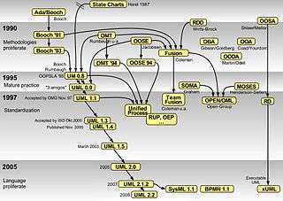
UML has been evolving since the second half of the 1990s and has its roots in the object-oriented methods developed in the late 1980s and early 1990s. The timeline (see image) shows the highlights of the history of object-oriented modeling methods and notation.
It is originally based on the notations of the Booch method, the object-modeling technique (OMT) and object-oriented software engineering (OOSE), which it has integrated into a single language.[4]
Rational Software Corporation hired James Rumbaugh from General Electric in 1994 and after that the company became the source for two of the most popular object-oriented modeling approaches of the day:[5] Rumbaugh's object-modeling technique (OMT) and Grady Booch's method. They were soon assisted in their efforts by Ivar Jacobson, the creator of the object-oriented software engineering (OOSE) method, who joined them at Rational in 1995.[1]
UML 1.x
Under the technical leadership of those three (Rumbaugh, Jacobson and Booch), a consortium called the UML Partners was organized in 1996 to complete the Unified Modeling Language (UML) specification, and propose it to the Object Management Group (OMG) for standardisation. The partnership also contained additional interested parties (for example HP, DEC, IBM and Microsoft). The UML Partners' UML 1.0 draft was proposed to the OMG in January 1997 by the consortium. During the same month the UML Partners formed a group, designed to define the exact meaning of language constructs, chaired by Cris Kobryn and administered by Ed Eykholt, to finalize the specification and integrate it with other standardization efforts. The result of this work, UML 1.1, was submitted to the OMG in August 1997 and adopted by the OMG in November 1997.[1][6]
After the first release a task force was formed[1] to improve the language, which released several minor revisions, 1.3, 1.4, and 1.5.[7]
The standards it produced (as well as the original standard) have been noted as being ambiguous and inconsistent.[8][9]
UML 2.x
UML 2.0 major revision replaced version 1.5 in 2005, which was developed with an enlarged consortium to improve the language further to reflect new experience on usage of its features.[10]
Although UML 2.1 was never released as a formal specification, versions 2.1.1 and 2.1.2 appeared in 2007, followed by UML 2.2 in February 2009. UML 2.3 was formally released in May 2010.[11] UML 2.4.1 was formally released in August 2011.[11] UML 2.5 was released in October 2012 as an "In process" version and was officially released in June 2015.[11]
There are four parts to the UML 2.x specification:
- The Superstructure that defines the notation and semantics for diagrams and their model elements
- The Infrastructure that defines the core metamodel on which the Superstructure is based
- The Object Constraint Language (OCL) for defining rules for model elements
- The UML Diagram Interchange that defines how UML 2 diagram layouts are exchanged
The current versions of these standards follow: UML Superstructure version 2.4.1, UML Infrastructure version 2.4.1, OCL version 2.3.1, and UML Diagram Interchange version 1.0.[12] It continues to be updated and improved by the revision task force, who resolve any issues with the language.[13]
Design
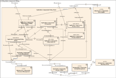
UML offers a way to visualize a system's architectural blueprints in a diagram (see image), including elements such as:[4]
- any activities (jobs);
- individual components of the system;
- and how they can interact with other software components;
- how the system will run;
- how entities interact with others (components and interfaces);
- external user interface.
Although originally intended for object-oriented design documentation, UML has been extended to a larger set of design documentation (as listed above),[14] and been found useful in many contexts.[15]
Software development methods
UML is not a development method by itself;[16] however, it was designed to be compatible with the leading object-oriented software development methods of its time, for example OMT, Booch method, Objectory and especially RUP that it was originally intended to be used with when work began at Rational Software.
Modeling
It is important to distinguish between the UML model and the set of diagrams of a system. A diagram is a partial graphic representation of a system's model. The set of diagrams need not completely cover the model and deleting a diagram does not change the model. The model may also contain documentation that drives the model elements and diagrams (such as written use cases).
UML diagrams represent two different views of a system model:[17]
- Static (or structural) view: emphasizes the static structure of the system using objects, attributes, operations and relationships. It includes class diagrams and composite structure diagrams.
- Dynamic (or behavioral) view: emphasizes the dynamic behavior of the system by showing collaborations among objects and changes to the internal states of objects. This view includes sequence diagrams, activity diagrams and state machine diagrams.
UML models can be exchanged among UML tools by using the XML Metadata Interchange (XMI) format.
Diagrams
| UML diagrams |
|---|
| Structural UML diagrams |
| Behavioral UML diagrams |
UML 2 has many types of diagrams, which are divided into two categories.[4] Some types represent structural information, and the rest represent general types of behavior, including a few that represent different aspects of interactions. These diagrams can be categorized hierarchically as shown in the following class diagram:[4]
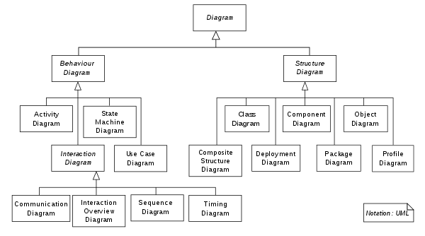
These diagrams may all contain comments or notes explaining usage, constraint, or intent.
Structure diagrams
Structure diagrams emphasize the things that must be present in the system being modeled. Since structure diagrams represent the structure, they are used extensively in documenting the software architecture of software systems. For example, the component diagram describes how a software system is split up into components and shows the dependencies among these components.

Behavior diagrams
Behavior diagrams emphasize what must happen in the system being modeled. Since behavior diagrams illustrate the behavior of a system, they are used extensively to describe the functionality of software systems. As an example, the activity diagram describes the business and operational step-by-step activities of the components in a system.


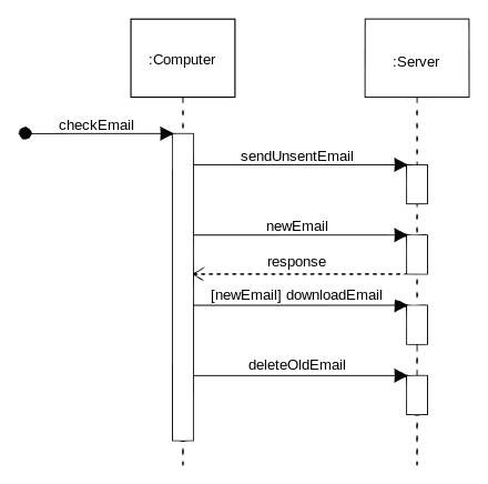
Interaction diagrams
Interaction diagrams, a subset of behavior diagrams, emphasize the flow of control and data among the things in the system being modeled. For example, the sequence diagram shows how objects communicate with each other in terms of a sequence of messages.

Meta modeling
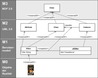
The Object Management Group (OMG) has developed a metamodeling architecture to define the UML, called the Meta-Object Facility.[18] MOF is designed as a four-layered architecture, as shown in the image at right. It provides a meta-meta model at the top, called the M3 layer. This M3-model is the language used by Meta-Object Facility to build metamodels, called M2-models.
The most prominent example of a Layer 2 Meta-Object Facility model is the UML metamodel, which describes the UML itself. These M2-models describe elements of the M1-layer, and thus M1-models. These would be, for example, models written in UML. The last layer is the M0-layer or data layer. It is used to describe runtime instances of the system.[19]
The meta-model can be extended using a mechanism called stereotyping. This has been criticised as being insufficient/untenable by Brian Henderson-Sellers and Cesar Gonzalez-Perez in "Uses and Abuses of the Stereotype Mechanism in UML 1.x and 2.0".[20]
Adoption
UML has been found useful in many design contexts.[15][21]
It has been treated, at times, as a design silver bullet, which has led to problems in its usage. Misuse of it includes excessive usage of it (design every little part of the system's code with it, which is unnecessary) and assuming that anyone can design anything with it (even those who haven't programmed).[22]
It is seen to be a large language, with many constructs in it. Some (including Jacobson) feel that there are too many and that this hinders the learning (and therefore usage) of it.[23]
Criticisms
Common criticisms of UML from industry include:[24]
- not useful: "[does] not offer them advantages over their current, evolved practices and representations"
- too complex, particularly for communication with clients: "unnecessarily complex" and "The best reason not to use UML is that it is not ‘readable’ for all stakeholders. How much is UML worth if a business user (the customer) can not understand the result of your modelling effort?"
- need to keep UML and code in sync, as with documentation generally
Critique of UML 1.x
- Cardinality notation
- As with database Chen, Bachman, and ISO ER diagrams, class models are specified to use "look-across" cardinalities, even though several authors (Merise,[25] Elmasri & Navathe[26] amongst others[27]) prefer same-side or "look-here" for roles and both minimum and maximum cardinalities. Recent researchers (Feinerer,[28] Dullea et. alia[29]) have shown that the "look-across" technique used by UML and ER diagrams is less effective and less coherent when applied to n-ary relationships of order strictly greater than 2.
- Feinerer says: "Problems arise if we operate under the look-across semantics as used for UML associations. Hartmann[30] investigates this situation and shows how and why different transformations fail.", and: "As we will see on the next few pages, the look-across interpretation introduces several difficulties which prevent the extension of simple mechanisms from binary to n-ary associations."
See also
- Object Oriented Role Analysis and Modeling
- Model-based testing
- Model-driven engineering
- Applications of UML
- List of Unified Modeling Language tools
References
This article is based on material taken from the Free On-line Dictionary of Computing prior to 1 November 2008 and incorporated under the "relicensing" terms of the GFDL, version 1.3 or later.
- 1 2 3 4 5 Unified Modeling Language User Guide, The (2 ed.). Addison-Wesley. 2005. p. 496. ISBN 0321267974. , See the sample content, look for history
- ↑ "ISO/IEC 19501:2005 - Information technology - Open Distributed Processing - Unified Modeling Language (UML) Version 1.4.2". Iso.org. 2005-04-01. Retrieved 2015-05-07.
- ↑ "ISO/IEC 19505-1:2012 - Information technology - Object Management Group Unified Modeling Language (OMG UML) - Part 1: Infrastructure". Iso.org. 2012-04-20. Retrieved 2014-04-10.
- 1 2 3 4 "OMG Unified Modeling Language (OMG UML), Superstructure. Version 2.4.1". Object Management Group. Retrieved 9 April 2014.
- ↑ Andreas Zendler (1997) Advanced Concepts, Life Cycle Models and Tools for Objeckt-Oriented Software Development. p.122
- ↑ "UML Specification version 1.1 (OMG document ad/97-08-11)". Omg.org. Retrieved 2011-09-22.
- ↑ "UML". Omg.org. Retrieved 2014-04-10.
- ↑ Génova et alia 2004 "Open Issues in Industrial Use Case Modeling"
- ↑ "Will UML 2.0 Be Agile or Awkward?" (PDF). Retrieved 2011-09-22.
- ↑ "UML 2.0". Omg.org. Retrieved 2011-09-22.
- 1 2 3 "UML". Omg.org. Retrieved 2011-09-22.
- ↑ OMG. "OMG Formal Specifications (Modeling and Metadata paragraph)". Retrieved 2016-02-12.
- ↑ "Issues for UML 2.6 Revision task Force mailing list". Omg.org. Retrieved 2014-04-10.
- ↑ Satish Mishra (1997). "Visual Modeling & Unified Modeling Language (UML): Introduction to UML". Rational Software Corporation. Accessed 9 November 2008.
- 1 2 "UML, Success Stories". Retrieved 9 April 2014.
- ↑ John Hunt (2000). The Unified Process for Practitioners: Object-oriented Design, UML and Java. Springer, 2000. ISBN 1-85233-275-1. p.5.door
- ↑ Jon Holt Institution of Electrical Engineers (2004). UML for Systems Engineering: Watching the Wheels IET, 2004, ISBN 0-86341-354-4. p.58
- ↑ Iman Poernomo (2006) "The Meta-Object Facility Typed" in: Proceeding SAC '06 Proceedings of the 2006 ACM symposium on Applied computing. pp. 1845-1849
- ↑ "UML 2.4.1 Infrastructure". Omg.org. 2011-08-05. Retrieved 2014-04-10.
- ↑ B. Henderson-Sellers; C. Gonzalez-Perez (2006). "Uses and Abuses of the Stereotype Mechanism in UML 1.x and 2.0". in: Model Driven Engineering Languages and Systems. Springer Berlin / Heidelberg.
- ↑ "UML 2.5: Do you even care?". "UML truly is ubiquitous"
- ↑ "Death by UML Fever".
- ↑ "Ivar Jacobson on UML, MDA, and the future of methodologies".
- ↑ Petre, Marian (2013). UML in practice (PDF). 35th International Conference on Software Engineering 18–26 May 2013. pp. 722–731.
The majority of those interviewed simply do not use UML, and those who do use it tend to do so selectively and often informally
- ↑ Hubert Tardieu, Arnold Rochfeld and René Colletti La methode MERISE: Principes et outils (Paperback - 1983)
- ↑ Elmasri, Ramez, B. Shamkant, Navathe, Fundamentals of Database Systems, third ed., Addison-Wesley, Menlo Park, CA, USA, 2000.
- ↑ ER 2004 : 23rd International Conference on Conceptual Modeling, Shanghai, China, 8-12 November 2004 Archived 27 May 2013 at the Wayback Machine.
- ↑ "A Formal Treatment of UML Class Diagrams as an Efficient Method for Configuration Management 2007" (PDF). Retrieved 2011-09-22.
- ↑ "James Dullea, Il-Yeol Song, Ioanna Lamprou - An analysis of structural validity in entity-relationship modeling 2002" (PDF). Retrieved 2011-09-22.
- ↑ ""Reasoning about participation constraints and Chen's constraints" S Hartmann - 2003" (PDF). Retrieved 2013-08-17.
Further reading
- Ambler, Scott William (2004). The Object Primer: Agile Model Driven Development with UML 2. Cambridge University Press. ISBN 0-521-54018-6.
- Chonoles, Michael Jesse; James A. Schardt (2003). UML 2 for Dummies. Wiley Publishing. ISBN 0-7645-2614-6.
- Fowler, Martin. UML Distilled: A Brief Guide to the Standard Object Modeling Language (3rd ed.). Addison-Wesley. ISBN 0-321-19368-7.
- Jacobson, Ivar; Grady Booch; James Rumbaugh (1998). The Unified Software Development Process. Addison Wesley Longman. ISBN 0-201-57169-2.
- Martin, Robert Cecil (2003). UML for Java Programmers. Prentice Hall. ISBN 0-13-142848-9.
- Noran, Ovidiu S. "Business Modelling: UML vs. IDEF" (PDF). Retrieved 2005-12-28.
- Horst Kargl. "Interactive UML Metamodel with additional Examples".
- Penker, Magnus; Hans-Erik Eriksson (2000). Business Modeling with UML. John Wiley & Sons. ISBN 0-471-29551-5.
External links
| Wikimedia Commons has media related to Unified Modeling Language. |
| Wikiversity has learning materials about UML |
| Actors |
|  | |||||||||||||||||||||
|---|---|---|---|---|---|---|---|---|---|---|---|---|---|---|---|---|---|---|---|---|---|---|---|
| Concepts |
| ||||||||||||||||||||||
| Diagrams |
| ||||||||||||||||||||||
| Derived languages | |||||||||||||||||||||||
| Other topics | |||||||||||||||||||||||
ISO standards by standard number | |
|---|---|
| 1–9999 |
|
| 10000–19999 |
|
| 20000+ | |
| |