Cooling tower


A cooling tower is a heat rejection device that rejects waste heat to the atmosphere through the cooling of a water stream to a lower temperature. Cooling towers may either use the evaporation of water to remove process heat and cool the working fluid to near the wet-bulb air temperature or, in the case of closed circuit dry cooling towers, rely solely on air to cool the working fluid to near the dry-bulb air temperature.
Common applications include cooling the circulating water used in oil refineries, petrochemical and other chemical plants, thermal power stations and HVAC systems for cooling buildings. The classification is based on the type of air induction into the tower: the main types of cooling towers are natural draft and induced draft cooling towers.
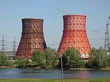
Cooling towers vary in size from small roof-top units to very large hyperboloid structures (as in the adjacent image) that can be up to 200 metres (660 ft) tall and 100 metres (330 ft) in diameter, or rectangular structures that can be over 40 metres (130 ft) tall and 80 metres (260 ft) long. The hyperboloid cooling towers are often associated with nuclear power plants,[1] although they are also used in some coal-fired plants and to some extent in some large chemical and other industrial plants. Although these large towers are very prominent, the vast majority of cooling towers are much smaller, including many units installed on or near buildings to discharge heat from air conditioning.
History

Cooling towers originated in the 19th century through the development of condensers for use with the steam engine.[2] Condensers use relatively cool water, via various means, to condense the steam coming out of the cylinders or turbines. This reduces the back pressure, which in turn reduces the steam consumption, and thus the fuel consumption, while at the same time increasing power and recycling boiler-water.[3] However the condensers require an ample supply of cooling water, without which they are impractical.[4][5] The consumption of cooling water by inland processing and power plants is estimated to reduce power availability for the majority of thermal power plants by 2040–2069.[6] While water usage is not an issue with marine engines, it forms a significant limitation for many land-based systems.
By the turn of the 20th century, several evaporative methods of recycling cooling water were in use in areas lacking an established water supply, as well as in urban locations where municipal water mains may not be of sufficient supply; be reliable in times of demand; or otherwise adequate to meet cooling needs.[2][5] In areas with available land, the systems took the form of cooling ponds; in areas with limited land, such as in cities, it took the form of cooling towers.[4][7]
These early towers were positioned either on the rooftops of buildings or as free-standing structures, supplied with air by fans or relying on natural airflow.[4][7] An American engineering textbook from 1911 described one design as "a circular or rectangular shell of light plate — in effect, a chimney stack much shortened vertically (20 to 40 ft. high) and very much enlarged laterally. At the top is a set of distributing troughs, to which the water from the condenser must be pumped; from these it trickles down over "mats" made of wooden slats or woven wire screens, which fill the space within the tower."[7]
A hyperboloid cooling tower was patented by the Dutch engineers Frederik van Iterson and Gerard Kuypers in 1918.[8] The first hyperboloid cooling towers were built in 1918 near Heerlen. The first ones in the United Kingdom were built in 1924 at Lister Drive power station in Liverpool, England to cool water used at a coal-fired electrical power station.[9]
Classification by use
Heating, ventilation and air conditioning (HVAC)
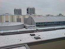
An HVAC (heating, ventilating, and air conditioning) cooling tower is used to dispose of ("reject") unwanted heat from a chiller. Water-cooled chillers are normally more energy efficient than air-cooled chillers due to heat rejection to tower water at or near wet-bulb temperatures. Air-cooled chillers must reject heat at the higher dry-bulb temperature, and thus have a lower average reverse-Carnot cycle effectiveness. In areas with a hot climate, large office buildings, hospitals, and schools typically use one or more cooling towers as part of their air conditioning systems. Generally, industrial cooling towers are much larger than HVAC towers.
HVAC use of a cooling tower pairs the cooling tower with a water-cooled chiller or water-cooled condenser. A ton of air-conditioning is defined as the removal of 12,000 BTU/hour (3500 W). The equivalent ton on the cooling tower side actually rejects about 15,000 BTU/hour (4400 W) due to the additional waste heat-equivalent of the energy needed to drive the chiller's compressor. This equivalent ton is defined as the heat rejection in cooling 3 US gallons/minute (1,500 pound/hour) of water 10 °F (6 °C), which amounts to 15,000 BTU/hour, assuming a chiller coefficient of performance (COP) of 4.0.[10] This COP is equivalent to an energy efficiency ratio (EER) of 14.
Cooling towers are also used in HVAC systems that have multiple water source heat pumps that share a common piping water loop. In this type of system, the water circulating inside the water loop removes heat from the condenser of the heat pumps whenever the heat pumps are working in the cooling mode, then the externally mounted cooling tower is used to remove heat from the water loop and reject it to the atmosphere. By contrast, when the heat pumps are working in heating mode, the condensers draw heat out of the loop water and reject it into the space to be heated. When the water loop is being used primarily to supply heat to the building, the cooling tower is normally shut down (and may be drained or winterized to prevent freeze damage), and heat is supplied by other means, usually from separate boilers.
Industrial cooling towers

Industrial cooling towers can be used to remove heat from various sources such as machinery or heated process material. The primary use of large, industrial cooling towers is to remove the heat absorbed in the circulating cooling water systems used in power plants, petroleum refineries, petrochemical plants, natural gas processing plants, food processing plants, semi-conductor plants, and for other industrial facilities such as in condensers of distillation columns, for cooling liquid in crystallization, etc.[11] The circulation rate of cooling water in a typical 700 MW coal-fired power plant with a cooling tower amounts to about 71,600 cubic metres an hour (315,000 US gallons per minute)[12] and the circulating water requires a supply water make-up rate of perhaps 5 percent (i.e., 3,600 cubic metres an hour).
If that same plant had no cooling tower and used once-through cooling water, it would require about 100,000 cubic metres an hour[13] and that amount of water would have to be continuously returned to the ocean, lake or river from which it was obtained and continuously re-supplied to the plant. Furthermore, discharging large amounts of hot water may raise the temperature of the receiving river or lake to an unacceptable level for the local ecosystem. Elevated water temperatures can kill fish and other aquatic organisms (see thermal pollution), or can also cause an increase in undesirable organisms such as invasive species of Zebra mussels or algae. A cooling tower serves to dissipate the heat into the atmosphere instead and wind and air diffusion spreads the heat over a much larger area than hot water can distribute heat in a body of water. Evaporative cooling water cannot be used for subsequent purposes (other than rain somewhere), whereas surface-only cooling water can be re-used. Some coal-fired and nuclear power plants located in coastal areas do make use of once-through ocean water. But even there, the offshore discharge water outlet requires very careful design to avoid environmental problems.
Petroleum refineries also have very large cooling tower systems. A typical large refinery processing 40,000 metric tonnes of crude oil per day (300,000 barrels (48,000 m3) per day) circulates about 80,000 cubic metres of water per hour through its cooling tower system.
The world's tallest cooling tower is the 202 metres (663 ft) tall cooling tower of Kalisindh Thermal Power Station in Jhalawar, Rajasthan, India.[14]

Classification by build
Package type

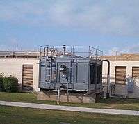
These types of cooling towers are factory preassembled, and can be simply transported on trucks, as they are compact machines. The capacity of package type towers is limited and, for that reason, they are usually preferred by facilities with low heat rejection requirements such as food processing plants, textile plants, some chemical processing plants, or buildings like hospitals, hotels, malls, automotive factories etc.
Due to their frequent use in or near residential areas, sound level control is a relatively more important issue for package type cooling towers.
Field erected type
Facilities such as power plants, steel processing plants, petroleum refineries, or petrochemical plants usually install field erected type cooling towers due to their greater capacity for heat rejection. Field erected towers are usually much larger in size compared to the package type cooling towers.
A typical field erected cooling tower has a pultruded fiber-reinforced plastic (FRP) structure, FRP cladding, a mechanical unit for air draft, drift eliminator, and fill.
Heat transfer methods
With respect to the heat transfer mechanism employed, the main types are:
- dry cooling towers operate by heat transfer through a surface that separates the working fluid from ambient air, such as in a tube to air heat exchanger, utilizing convective heat transfer. They do not use evaporation.
- wet cooling towers (or open circuit cooling towers) operate on the principle of evaporative cooling. The working fluid and the evaporated fluid (usually water) are one and the same.
- fluid coolers (or closed circuit cooling towers) are hybrids that pass the working fluid through a tube bundle, upon which clean water is sprayed and a fan-induced draft applied. The resulting heat transfer performance is much closer to that of a wet cooling tower, with the advantage provided by a dry cooler of protecting the working fluid from environmental exposure and contamination.
In a wet cooling tower (or open circuit cooling tower), the warm water can be cooled to a temperature lower than the ambient air dry-bulb temperature, if the air is relatively dry (see dew point and psychrometrics). As ambient air is drawn past a flow of water, a small portion of the water evaporates, and the energy required to evaporate that portion of the water is taken from the remaining mass of water, thus reducing its temperature. Approximately 970 BTU of heat energy is absorbed for each pound of evaporated water (2 MJ/kg). Evaporation results in saturated air conditions, lowering the temperature of the water processed by the tower to a value close to wet-bulb temperature, which is lower than the ambient dry-bulb temperature, the difference determined by the initial humidity of the ambient air.
To achieve better performance (more cooling), a medium called fill is used to increase the surface area and the time of contact between the air and water flows. Splash fill consists of material placed to interrupt the water flow causing splashing. Film fill is composed of thin sheets of material (usually PVC) upon which the water flows. Both methods create increased surface area and time of contact between the fluid (water) and the gas (air), to improve heat transfer.
Air flow generation methods

With respect to drawing air through the tower, there are three types of cooling towers:
- Natural draft — Utilizes buoyancy via a tall chimney. Warm, moist air naturally rises due to the density differential compared to the dry, cooler outside air. Warm moist air is less dense than drier air at the same pressure. This moist air buoyancy produces an upwards current of air through the tower.
- Mechanical draught — Uses power-driven fan motors to force or draw air through the tower.
- Induced draught — A mechanical draft tower with a fan at the discharge (at the top) which pulls air up through the tower. The fan induces hot moist air out the discharge. This produces low entering and high exiting air velocities, reducing the possibility of recirculation in which discharged air flows back into the air intake. This fan/fin arrangement is also known as draw-through.
- Forced draught — A mechanical draft tower with a blower type fan at the intake. The fan forces air into the tower, creating high entering and low exiting air velocities. The low exiting velocity is much more susceptible to recirculation. With the fan on the air intake, the fan is more susceptible to complications due to freezing conditions. Another disadvantage is that a forced draft design typically requires more motor horsepower than an equivalent induced draft design. The benefit of the forced draft design is its ability to work with high static pressure. Such setups can be installed in more-confined spaces and even in some indoor situations. This fan/fill geometry is also known as blow-through.
- Fan assisted natural draught — A hybrid type that appears like a natural draft setup, though airflow is assisted by a fan.
Hyperboloid (sometimes incorrectly known as hyperbolic) cooling towers have become the design standard for all natural-draft cooling towers because of their structural strength and minimum usage of material. The hyperboloid shape also aids in accelerating the upward convective air flow, improving cooling efficiency. These designs are popularly associated with nuclear power plants. However, this association is misleading, as the same kind of cooling towers are often used at large coal-fired power plants as well. Conversely, not all nuclear power plants have cooling towers, and some instead cool their heat exchangers with lake, river or ocean water.
Categorization by air-to-water flow
Crossflow

Crossflow is a design in which the air flow is directed perpendicular to the water flow (see diagram at left). Air flow enters one or more vertical faces of the cooling tower to meet the fill material. Water flows (perpendicular to the air) through the fill by gravity. The air continues through the fill and thus past the water flow into an open plenum volume. Lastly, a fan forces the air out into the atmosphere.
A distribution or hot water basin consisting of a deep pan with holes or nozzles in its bottom is located near the top of a crossflow tower. Gravity distributes the water through the nozzles uniformly across the fill material.
Advantages of the crossflow design:
- Gravity water distribution allows smaller pumps and maintenance while in use.
- Non-pressurized spray simplifies variable flow.
- Typically lower initial and long-term cost, mostly due to pump requirements.
 Package Crossflow cooling tower
Disadvantages of the crossflow design:
- More prone to freezing than counterflow designs.
- Variable flow is useless in some conditions.
- More prone to dirt buildup in the fill than counterflow designs, especially in dusty or sandy areas.
Counterflow


In a counterflow design, the air flow is directly opposite to the water flow (see diagram at left). Air flow first enters an open area beneath the fill media, and is then drawn up vertically. The water is sprayed through pressurized nozzles near the top of the tower, and then flows downward through the fill, opposite to the air flow.
Advantages of the counterflow design:
- Spray water distribution makes the tower more freeze-resistant.
- Breakup of water in spray makes heat transfer more efficient.
Disadvantages of the counterflow design:
- Typically higher initial and long-term cost, primarily due to pump requirements.
- Difficult to use variable water flow, as spray characteristics may be negatively affected.
- Typically noisier, due to the greater water fall height from the bottom of the fill into the cold water basin
Common aspects
Common aspects of both designs:
- The interactions of the air and water flow allow a partial equalization of temperature, and evaporation of water.
- The air, now saturated with water vapor, is discharged from the top of the cooling tower.
- A "collection basin" or "cold water basin" is used to collect and contain the cooled water after its interaction with the air flow.
Both crossflow and counterflow designs can be used in natural draft and in mechanical draft cooling towers.
Wet cooling tower material balance
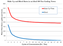
Quantitatively, the material balance around a wet, evaporative cooling tower system is governed by the operational variables of make-up flow rate, evaporation and windage losses, draw-off rate, and the concentration cycles.[15][16]
In the adjacent diagram, water pumped from the tower basin is the cooling water routed through the process coolers and condensers in an industrial facility. The cool water absorbs heat from the hot process streams which need to be cooled or condensed, and the absorbed heat warms the circulating water (C). The warm water returns to the top of the cooling tower and trickles downward over the fill material inside the tower. As it trickles down, it contacts ambient air rising up through the tower either by natural draft or by forced draft using large fans in the tower. That contact causes a small amount of the water to be lost as windage/drift (W) and some of the water (E) to evaporate. The heat required to evaporate the water is derived from the water itself, which cools the water back to the original basin water temperature and the water is then ready to recirculate. The evaporated water leaves its dissolved salts behind in the bulk of the water which has not been evaporated, thus raising the salt concentration in the circulating cooling water. To prevent the salt concentration of the water from becoming too high, a portion of the water is drawn off/blown down (D) for disposal. Fresh water make-up (M) is supplied to the tower basin to compensate for the loss of evaporated water, the windage loss water and the draw-off water.

Using these flow rates and concentration dimensional units:
| M | = Make-up water in m³/h |
| C | = Circulating water in m³/h |
| D | = Draw-off water in m³/h |
| E | = Evaporated water in m³/h |
| W | = Windage loss of water in m³/h |
| X | = Concentration in ppmw (of any completely soluble salts ... usually chlorides) |
| XM | = Concentration of chlorides in make-up water (M), in ppmw |
| XC | = Concentration of chlorides in circulating water (C), in ppmw |
| Cycles | = Cycles of concentration = XC / XM (dimensionless) |
| ppmw | = parts per million by weight |
A water balance around the entire system is then:[16]
- M = E + D + W
Since the evaporated water (E) has no salts, a chloride balance around the system is:[16]

and, therefore:[16]

From a simplified heat balance around the cooling tower:

| where: | |
| HV | = latent heat of vaporization of water = 2260 kJ / kg |
| ΔT | = water temperature difference from tower top to tower bottom, in °C |
| cp | = specific heat of water = 4.184 kJ / (kg°C) |

Windage (or drift) losses (W) is the amount of total tower water flow that is evaporated into the atmosphere. From large-scale industrial cooling towers, in the absence of manufacturer's data, it may be assumed to be:
- W = 0.3 to 1.0 percent of C for a natural draft cooling tower without windage drift eliminators
- W = 0.1 to 0.3 percent of C for an induced draft cooling tower without windage drift eliminators
- W = about 0.005 percent of C (or less) if the cooling tower has windage drift eliminators
- W = about 0.0005 percent of C (or less) if the cooling tower has windage drift eliminators and uses sea water as make-up water.
Cycles of concentration
Cycle of concentration represents the accumulation of dissolved minerals in the recirculating cooling water. Discharge of draw-off (or blowdown) is used principally to control the buildup of these minerals.
The chemistry of the make-up water, including the amount of dissolved minerals, can vary widely. Make-up waters low in dissolved minerals such as those from surface water supplies (lakes, rivers etc.) tend to be aggressive to metals (corrosive). Make-up waters from ground water supplies (such as wells) are usually higher in minerals, and tend to be scaling (deposit minerals). Increasing the amount of minerals present in the water by cycling can make water less aggressive to piping; however, excessive levels of minerals can cause scaling problems.
As the cycles of concentration increase, the water may not be able to hold the minerals in solution. When the solubility of these minerals have been exceeded they can precipitate out as mineral solids and cause fouling and heat exchange problems in the cooling tower or the heat exchangers. The temperatures of the recirculating water, piping and heat exchange surfaces determine if and where minerals will precipitate from the recirculating water. Often a professional water treatment consultant will evaluate the make-up water and the operating conditions of the cooling tower and recommend an appropriate range for the cycles of concentration. The use of water treatment chemicals, pretreatment such as water softening, pH adjustment, and other techniques can affect the acceptable range of cycles of concentration.
Concentration cycles in the majority of cooling towers usually range from 3 to 7. In the United States, many water supplies use well water which has significant levels of dissolved solids. On the other hand, one of the largest water supplies, for New York City, has a surface rainwater source quite low in minerals; thus cooling towers in that city are often allowed to concentrate to 7 or more cycles of concentration.
Since higher cycles of concentration represent less make-up water, water conservation efforts may focus on increasing cycles of concentration.[17] Highly treated recycled water may be an effective means of reducing cooling tower consumption of potable water, in regions where potable water is scarce.[18]
Water treatment
Besides treating the circulating cooling water in large industrial cooling tower systems to minimize scaling and fouling, the water should be filtered to remove particulates, and also be dosed with biocides and algaecides to prevent growths that could interfere with the continuous flow of the water.[15] Under certain conditions, a biofilm of micro-organisms such as bacteria, fungi and algae can grow very rapidly in the cooling water, and can reduce the heat transfer efficiency of the cooling tower. Biofilm can be reduced or prevented by using chlorine or other chemicals. A normal industrial practice is to use two biocides i.e. oxidising and non-oxidising to complement each other's strength and weaknesses and to ensure a broader spectrum of attack.
Legionnaires' disease
_2.jpg)
Another very important reason for using biocides in cooling towers is to prevent the growth of Legionella, including species that cause legionellosis or Legionnaires' disease, most notably L. pneumophila,[19] or Mycobacterium avium.[20] The various Legionella species are the cause of Legionnaires' disease in humans and transmission is via exposure to aerosols—the inhalation of mist droplets containing the bacteria. Common sources of Legionella include cooling towers used in open recirculating evaporative cooling water systems, domestic hot water systems, fountains, and similar disseminators that tap into a public water supply. Natural sources include freshwater ponds and creeks.
French researchers found that Legionella bacteria travelled up to 6 kilometres (3.7 mi) through the air from a large contaminated cooling tower at a petrochemical plant in Pas-de-Calais, France. That outbreak killed 21 of the 86 people who had a laboratory-confirmed infection.[21]
Drift (or windage) is the term for water droplets of the process flow allowed to escape in the cooling tower discharge. Drift eliminators are used in order to hold drift rates typically to 0.001–0.005% of the circulating flow rate. A typical drift eliminator provides multiple directional changes of airflow to prevent the escape of water droplets. A well-designed and well-fitted drift eliminator can greatly reduce water loss and potential for Legionella or water treatment chemical exposure.
Many governmental agencies, cooling tower manufacturers and industrial trade organizations have developed design and maintenance guidelines for preventing or controlling the growth of Legionella in cooling towers. Below is a list of sources for such guidelines:
- "Centers for Disease Control and Prevention (CDC)" (PDF). (4.99 MB) - Procedure for Cleaning Cooling Towers and Related Equipment (pages 225 and 226)
- "Cooling Technology Institute" (PDF). (240 KB) - Best Practices for Control of Legionella, July, 2006
- "Association of Water Technologies" (PDF). (964 KB) - Legionella 2003: An Update and Statement
- "California Energy Commission" (PDF). (194 KB) - Cooling Water Management Program Guidelines For Wet and Hybrid Cooling Towers at Power Plants
- "SPX Cooling Technologies" (PDF). (119 KB) - Cooling Towers Maintenance Procedures
- "SPX Cooling Technologies" (PDF). (789 KB) - ASHRAE Guideline 12-2000 - Minimizing the Risk of Legionellosis
- "SPX Cooling Technologies" (PDF). (83.1 KB) - Cooling Tower Inspection Tips {especially page 3 of 7}
- "Tower Tech Modular Cooling Towers" (PDF). (109 KB) - Legionella Control
- "GE Infrastructure Water & Process Technologies Betz Dearborn" (PDF). (195 KB) - Chemical Water Treatment Recommendations For Reduction of Risks Associated with Legionella in Open Recirculating Cooling Water Systems
Terminology

- Windage or Drift — Water droplets that are carried out of the cooling tower with the exhaust air. Drift droplets have the same concentration of impurities as the water entering the tower. The drift rate is typically reduced by employing baffle-like devices, called drift eliminators, through which the air must travel after leaving the fill and spray zones of the tower. Drift can also be reduced by using warmer entering cooling tower temperatures.
- Blow-out — Water droplets blown out of the cooling tower by wind, generally at the air inlet openings. Water may also be lost, in the absence of wind, through splashing or misting. Devices such as wind screens, louvers, splash deflectors and water diverters are used to limit these losses.
- Plume — The stream of saturated exhaust air leaving the cooling tower. The plume is visible when water vapor it contains condenses in contact with cooler ambient air, like the saturated air in one's breath fogs on a cold day. Under certain conditions, a cooling tower plume may present fogging or icing hazards to its surroundings. Note that the water evaporated in the cooling process is "pure" water, in contrast to the very small percentage of drift droplets or water blown out of the air inlets.
- Draw-off or Blow-down — The portion of the circulating water flow that is removed (usually discharged to a drain) in order to maintain the amount of Total Dissolved Solids (TDS) and other impurities at an acceptably low level. Higher TDS concentration in solution may result from greater cooling tower efficiency. However the higher the TDS concentration, the greater the risk of scale, biological growth and corrosion. The amount of blow-down is primarily designated by measuring by the electrical conductivity of the circulating water. Biological growth, scaling and corrosion can be prevented by chemicals (respectively, biocide, sulfuric acid, corrosion inhibitor). On the other hand, the only practical way to decrease the electrical conductivity is by increasing the amount of blow-down discharge and subsequently increasing the amount of clean make-up water.
- Zero bleed for cooling towers, also called zero blow-down for cooling towers, is a process for significantly reducing the need for bleeding water with residual solids from the system by enabling the water to hold more solids in solution.[22][23][24]
- Make-up — The water that must be added to the circulating water system in order to compensate for water losses such as evaporation, drift loss, blow-out, blow-down, etc.
- Noise — Sound energy emitted by a cooling tower and heard (recorded) at a given distance and direction. The sound is generated by the impact of falling water, by the movement of air by fans, the fan blades moving in the structure, vibration of the structure, and the motors, gearboxes or drive belts.
- Approach — The approach is the difference in temperature between the cooled-water temperature and the entering-air wet bulb temperature (twb). Since the cooling towers are based on the principles of evaporative cooling, the maximum cooling tower efficiency depends on the wet bulb temperature of the air. The wet-bulb temperature is a type of temperature measurement that reflects the physical properties of a system with a mixture of a gas and a vapor, usually air and water vapor
- Range — The range is the temperature difference between the warm water inlet and cooled water exit.
- Fill — Inside the tower, fills are added to increase contact surface as well as contact time between air and water, to provide better heat transfer. The efficiency of the tower depends on the selection and amount of fill. There are two types of fills that may be used:
- Film type fill (causes water to spread into a thin film)
- Splash type fill (breaks up falling stream of water and interrupts its vertical progress)
- Full-Flow Filtration — Full-flow filtration continuously strains particulates out of the entire system flow. For example, in a 100-ton system, the flow rate would be roughly 300 gal/min. A filter would be selected to accommodate the entire 300 gal/min flow rate. In this case, the filter typically is installed after the cooling tower on the discharge side of the pump. While this is the ideal method of filtration, for higher flow systems it may be cost-prohibitive.
- Side-Stream Filtration — Side-stream filtration, although popular and effective, does not provide complete protection. With side-stream filtration, a portion of the water is filtered continuously. This method works on the principle that continuous particle removal will keep the system clean. Manufacturers typically package side-stream filters on a skid, complete with a pump and controls. For high flow systems, this method is cost-effective. Properly sizing a side-stream filtration system is critical to obtain satisfactory filter performance, but there is some debate over how to properly size the side-stream system. Many engineers size the system to continuously filter the cooling tower basin water at a rate equivalent to 10% of the total circulation flow rate. For example, if the total flow of a system is 1,200 gal/min (a 400-ton system), a 120 gal/min side-stream system is specified.
- Cycle of concentration — Maximum allowed multiplier for the amount of miscellaneous substances in circulating water compared to the amount of those substances in make-up water.
- Treated timber — A structural material for cooling towers which was largely abandoned about 10 years ago. It is still used occasionally due to its low initial costs, in spite of its short life expectancy. The life of treated timber varies a lot, depending on the operating conditions of the tower, such as frequency of shutdowns, treatment of the circulating water, etc. Under proper working conditions, the estimated life of treated timber structural members is about 10 years.
- Leaching — The loss of wood preservative chemicals by the washing action of the water flowing through a wood structure cooling tower.
- Pultruded FRP — A common structural material for smaller cooling towers, fibre-reinforced plastic (FRP) is known for its high corrosion-resistance capabilities. Pultuded FRP is produced using pultrusion technology, and has become the most common structural material for small cooling towers. It offers lower costs and requires less maintenance compared to reinforced concrete, which is still in use for large structures.
Fog production

Under certain ambient conditions, plumes of water vapor (fog) can be seen rising out of the discharge from a cooling tower, and can be mistaken as smoke from a fire. If the outdoor air is at or near saturation, and the tower adds more water to the air, saturated air with liquid water droplets can be discharged, which is seen as fog. This phenomenon typically occurs on cool, humid days, but is rare in many climates.
This phenomenon can be prevented by decreasing the relative humidity of the saturated discharge air. For that purpose, in hybrid towers, saturated discharge air is mixed with heated low relative humidity air. Some air enters the tower above drift eliminator level, passing through heat exchangers. The relative humidity of the dry air is even more decreased instantly as being heated while entering the tower. The discharged mixture has a relatively lower relative humidity and the fog is invisible.
Salt emission pollution
When wet cooling towers with seawater make-up are installed in various industries located in or near coastal areas, the drift of fine droplets emitted from the cooling towers contain nearly 6% sodium chloride which deposits on the nearby land areas. This deposition of sodium salts on the nearby agriculture/vegetative lands can convert them into sodic saline or sodic alkaline soils depending on the nature of the soil and enhance the sodicity of ground and surface water. The salt deposition problem from such cooling towers aggravates where national pollution control standards are not imposed or not implemented to minimize the drift emissions from wet cooling towers using seawater make-up.[25]
Respirable suspended particulate matter, of less than 10 micrometers (µm) in size, can be present in the drift from cooling towers. Larger particles above 10 µm in size are generally filtered out in the nose and throat via cilia and mucus but particulate matter smaller than 10 µm, referred to as PM10, can settle in the bronchi and lungs and cause health problems. Similarly, particles smaller than 2.5 µm, (PM2.5), tend to penetrate into the gas exchange regions of the lung, and very small particles (less than 100 nanometers) may pass through the lungs to affect other organs. Though the total particulate emissions from wet cooling towers with fresh water make-up is much less, they contain more PM10 and PM2.5 than the total emissions from wet cooling towers with sea water make-up. This is due to lesser salt content in fresh water drift (below 2,000 ppm) compared to the salt content of sea water drift (60,000 ppm).[25]
Use as a flue-gas stack


At some modern power stations equipped with flue gas purification, such as the Großkrotzenburg Power Station and the Rostock Power Station, the cooling tower is also used as a flue-gas stack (industrial chimney), thus saving the cost of a separate chimney structure. At plants without flue gas purification, problems with corrosion may occur, due to reactions of raw flue gas with water to form acids.
Sometimes, natural draft cooling towers are constructed with structural steel in place of concrete (RCC) when the construction time of natural draft cooling tower is exceeding the construction time of the rest of the plant or the local soil is of poor strength to bear the heavy weight of RCC cooling towers or cement prices are higher at a site to opt for cheaper natural draft cooling towers made of structural steel.
Operation and Maintenance
- Surfaces with any visible biofilm (i.e., slime) should be cleaned.
- Disinfectant and other chemical levels in cooling towers and hot tubs should be continuously maintained and regularly monitored.[26]
Operation in freezing weather
Some cooling towers (such as smaller building air conditioning systems) are shut down seasonally, drained, and winterized to prevent freeze damage.
During the winter, other sites continuously operate cooling towers with 40 °F (4 °C) water leaving the tower. Basin heaters, tower draindown, and other freeze protection methods are often employed in cold climates. Operational cooling towers with malfunctions can freeze during very cold weather. Typically, freezing starts at the corners of a cooling tower with a reduced or absent heat load. Severe freezing conditions can create growing volumes of ice, resulting in increased structural loads which can cause structural damage or collapse.
To prevent freezing, the following procedures are used:
- The use of water modulating by-pass systems is not recommended during freezing weather. In such situations, the control flexibility of variable speed motors, two-speed motors, and/or two-speed motors multi-cell towers should be considered a requirement.[27]
- Do not operate the tower unattended. Remote sensors and alarms may be installed to monitor tower conditions.
- Do not operate the tower without a heat load. Basin heaters may be used to keep the water in the tower pan at an above-freezing temperature. Heat trace ("heating tape") is a resistive heating element that is installed along water pipes to prevent freezing in cold climates.
- Maintain design water flow rate over the tower fill.
- Manipulate or reduce airflow to maintain water temperature above freezing point.[28]
Fire hazard
Cooling towers constructed in whole or in part of combustible materials can support internal fire propagation. Such fires can become very intense, due to the high surface-volume ratio of the towers, and fires can be further intensified by natural convection or fan-assisted draft. The resulting damage can be sufficiently severe to require the replacement of the entire cell or tower structure. For this reason, some codes and standards[29] recommend that combustible cooling towers be provided with an automatic fire sprinkler system. Fires can propagate internally within the tower structure when the cell is not in operation (such as for maintenance or construction), and even while the tower is in operation, especially those of the induced-draft type, because of the existence of relatively dry areas within the towers.[30]
Structural stability
Being very large structures, cooling towers are susceptible to wind damage, and several spectacular failures have occurred in the past. At Ferrybridge power station on 1 November 1965, the station was the site of a major structural failure, when three of the cooling towers collapsed owing to vibrations in 85 mph (137 km/h) winds. Although the structures had been built to withstand higher wind speeds, the shape of the cooling towers caused westerly winds to be funnelled into the towers themselves, creating a vortex. Three out of the original eight cooling towers were destroyed, and the remaining five were severely damaged. The towers were later rebuilt and all eight cooling towers were strengthened to tolerate adverse weather conditions. Building codes were changed to include improved structural support, and wind tunnel tests were introduced to check tower structures and configuration.
See also
References
- ↑ CleanEnergy Footprints (cleanenergy.org). Identifying Nuclear Reactors in Google Earth Retrieved 5/19/2014
- 1 2 International Correspondence Schools (1902). A Textbook on Steam Engineering. Scranton, Pa.: International Textbook Co. 33-34 of Section 29:"Condensers".
- ↑ Croft, Terrell, ed. (1922). Steam-Engine Principles and Practice. New York: McGraw-Hill. pp. 283–286.
- 1 2 3 Heck, Robert Culbertson Hays (1911). The Steam Engine and Turbine: A Text-Book for Engineering Colleges. New York: D. Van Nostrand. pp. 569–570.
- 1 2 Watson, Egbert P. (1 Jan 1906). "Power plant and allied industries". The Engineer (with Which is Incorporated Steam Engineering). Chicago: Taylor Publishing Co. 43 (1): 69–72.
- ↑ van Vliet, Michelle T. H.; Wiberg, David; Leduc, Sylvain; Riahi, Keywan (4 January 2016). "Power-generation system vulnerability and adaptation to changes in climate and water resources". doi:10.1038/nclimate2903. Retrieved 28 March 2016.
- 1 2 3 Snow, Walter B. (1908). The Steam Engine: A Practical Guide to the Construction, Operation, and care of Steam Engines, Steam Turbines, and Their Accessories. Chicago: American School of Correspondence. pp. 43–46.
- ↑ UK Patent No. 108,863
- ↑ "Power Plant Cooling Towers Like Big Milk Bottle" Popular Mechanics, February 1930 bottom-left of pg 201
- ↑ Cheremisinoff, Nicholas (2000). Handbook of Chemical Processing Equipment. Butterworth-Heinemann. p. 69. ISBN 9780080523828.
- ↑ U.S. Environmental Protection Agency (EPA). (1997). Profile of the Fossil Fuel Electric Power Generation Industry (Report). Washington, D.C. Document No. EPA/310-R-97-007. p. 79.
- ↑ Cooling System Retrofit Costs EPA Workshop on Cooling Water Intake Technologies, John Maulbetsch, Maulbetsch Consulting, May 2003
- ↑ Thomas J. Feeley, III, Lindsay Green, James T. Murphy, Jeffrey Hoffmann, and Barbara A. Carney (2005). "Department of Energy/Office of Fossil Energy’s Power Plant Water Management R&D Program." U.S. Department of Energy, July 2005.
- ↑ Comansa Jie builds the world’s highest cooling towers
- 1 2 Beychok, Milton R. (1967). Aqueous Wastes from Petroleum and Petrochemical Plants (1st ed.). John Wiley and Sons. LCCN 67019834. (available in many university libraries)
- 1 2 3 4 Milton R. Beychok (October 1952). "How To Calculate Cooling Tower Control Variables". Petroleum Processing: 1452–1456.
- ↑ "Best Management Practice Cooling Tower Management". Energy.gov. Department of Energy. 30 April 2005. Retrieved 16 June 2014.
- ↑ San Diego County Water Authority (July 2009). "Technical Information for Cooling Towers Using Recycled Water" (PDF). www.sdcwa.org. San Diego County Water Authority. Retrieved 18 June 2014.
- ↑ Ryan K.J.; Ray C.G. (editors) (2004). Sherris Medical Microbiology (4th ed.). McGraw Hill. ISBN 0-8385-8529-9.
- ↑ Centers for Disease Control and Prevention - Emerging Infectious Diseases (page 495)
- ↑ Airborne Legionella May Travel Several Kilometres (access requires free registration) Archived 22 September 2008 at the Wayback Machine.
- ↑ William H Clark (1997), Retrofitting for energy conservation, McGraw-Hill Professional, p. 66, ISBN 978-0-07-011920-8
- ↑ Institute of Industrial Engineers 1981- (1982), Proceedings, Volume 1982, Institute of Industrial Engineers/American Institute of Industrial Engineers, p. 101
- ↑ Mathie, Alton J. (1998), Chemical treatment for cooling water, Fairmont Press, p. 86, ISBN 978-0-88173-253-5
- 1 2 Wet Cooling Tower Guidance For Particulate Matter, Environment Canada, Retrieved on 2013-01-29
- ↑ DEVELOPING A LEGIONELLA WATER MANAGEMENT PROGRAM | CDC | June 6, 2016, Page 13 {17 of 32}
- ↑ http://spxcooling.com/library/detail/cooling-tower-fundamentals SPX Cooling Technologies MARLEY, Cooling Tower Fundamentals Page 73 (75 of 119) Column 2, Last Paragraph
- ↑ "SPX Cooling Technologies: Operating Cooling Towers in Freezing Weather" (PDF). (1.45 MB)
- ↑ National Fire Protection Association (NFPA). NFPA 214, Standard on Water-Cooling Towers.
- ↑ NFPA 214, Standard on Water-Cooling Towers. Section A1.1
External links
| Wikimedia Commons has media related to Cooling towers. |
- What is a cooling tower? - Cooling Technology Institute
- "Cooling Towers" - includes diagrams - Virtual Nuclear Tourist
- Wet cooling tower guidance for particulate matter, Environment Canada.